Brian Cornell

I designed the BGFD based on my personal experience of designing & installing a permitted off-grid solar system:
- 7kW PV array (2 strings of 3.5kW each),
- MidNite Barcelona charger,
- Schneider Conext XW Pro 7kW inverter,
- 30kW of Discover Energy AES LiFePo4 battery storage.
Disclaimer: I am not a licensed Electrician or PE and my experience is limited to working on the above. What I am presenting here is not recognized by UL or the NFPA (National Fire Protection Association - author of the NEC).
I'll start here by covering the BGFD and use the logs to in an attempt to explain the NEC requirements, the concerns with meeting them, and the alternatives (which led me to the BGFD).
So, what problem does the BGFD solve? Simply put, it provides ground fault detection for the battery system that could lead to equipment failure & fire; but unlike the NEC solution it allows the use of conventional gauge grounding conductors (typically 6 AWG) which in turn allows the use of the grounding bus bars found in AC distribution panels (the 'star' grounding point). All of this results in a simpler, safer, and lower cost system.
BGFD Specifications
- Supply operating voltage: 20-80V DC
- Supply maximum continuous current: 35mA @ 20V DC
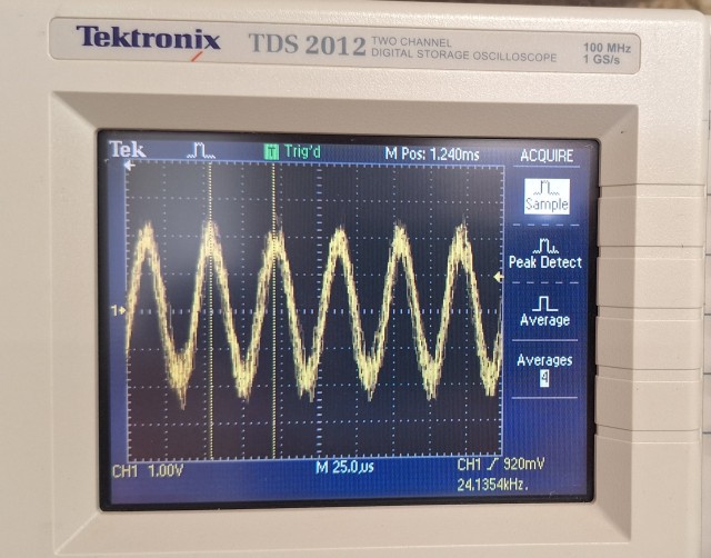
- Sensor operating frequency: 24kHz
- Trip (fault) current: Approximately 3A
- Response time: 7mS
- Number of shutdown circuits: 2 (isolated)
- Shutdown circuit max voltage: 30V DC
- Shutdown circuit max current: 500mA
- Shutdown circuit max power: 15W
- Operating temperature: -25C - +70C
- Enclosure rating: NEMA 1, indoor
Description & Operation
The system consists of the magnetic sensor (toroid) and control unit. The control unit is designed to be powered directly from 24~48V battery systems. The control unit contains a normally open (NO) 2-pole relay to accommodate two rapid shutdown circuits. During normal operation the relay is energized to close the rapid shutdown circuits. When a fault occurs the relay opens to initiate rapid shutdown.
The response time, from start of the fault event to relay opening, is 7mS. The relay remains open until the Reset button is pushed or the unit is power-cycled (and the fault has cleared). When powered by the battery system it is protecting, the unit will power down when a fault occurs. There is no advantage to powering the unit from an alternate source since operator intervention is required to restart the system.
For safety, when the unit loses power/is off the relay’s shutdown circuits are open to prevent the system from starting. The Bypass switch is used to bypass the relay (e.g., close the rapid shutdown circuits) to allow system startup.
LEDs provide operating status:
- Status is on when the unit is powered and there is no active fault.
- Trip illuminates when a fault has been detected (the relay is open).
- Bypass indicates that the bypass switch is active. Detected faults will not initiate a rapid shutdown (but the Trip LED will illuminate).
There isn’t a built-in test function since there is no way to properly include the sensor in the test.
Recommended test procedure
- Place the unit in bypass.
- Pass a section of wire (2~3ft) thru the toroid.
- Short the ends together.
- If the unit is operating properly the Status LED will turn off and the Trip LED illuminates & remains on.
- Remove the wire & confirm the status LED turns back on.
- Press the reset button to clear the trip (Trip LED turns off).
- Switch off bypass.
Note that this system is a detector and not an interruptor: it initiates the interrupt by opening the rapid shutdown circuits but relies on the source equipment to complete the interrupt operation.
Installation
- Shut down the battery & connected equipment.
- Connect the ground fault detector V-/+ terminals to the battery bus via 20 AWG wire and a 2A fast acting fuse.
- Route the battery grounding conductor thru the sensor and connect its leads to the sense terminals (polarity doesn’t matter).
- Connect the shutdown circuits to the SD1 &...