Pranav Upadhyay
-
Final Status: AI and Manual Control Working, UNO Q to ESP32 Link Not Yet Complete
8 minutes ago • 0 commentsHere is an honest summary of where the project stands at judging time.
What works
- On-device AI detection. Our model detects markers of different colours live from the overhead camera, running entirely on the Arduino UNO Q with no network connection. For each marker it reports the colour, the position on the table in millimetres, and the orientation.
- Workspace calibration. Four ArUco markers map camera pixels to real millimetres on the table. Locked camera settings keep detection stable under the hall lighting.
- Planning on the UNO Q. From the detections, the UNO Q plans the full task and works out every joint angle: approach the marker, grasp, trace the line around the obstacle, return the marker, go home. In dry-run mode the whole sequence runs against a simulated arm and logs every MOVE command it would send to the ESP32.
- Manual control of the arm. The ESP32 firmware drives all four servos smoothly from the two joysticks.
1. On power-up, the arm eases slowly into its measured home pose.
2. Each joint's speed is capped, so it never snaps.
3. The pose is saved every second, so after a power cut the arm resumes from where it actually was.
4. The J1 button freezes the arm instantly, and this is our safety kill switch.What doesn't work yet
The missing piece is the link between the two boards. The UNO Q produces the correct commands, and the ESP32 can move the servos under joystick control, but two steps aren't finished:
- UNO Q to ESP32 serial communication. The UNO Q sends PING and MOVE commands over USB serial. The ESP32 doesn't yet receive and answer them reliably.
- ESP32 turning received commands into servo motion. Once a command arrives, the ESP32 needs to read out the joint angles and drive each servo to them through the same smooth, speed-limited motion it already uses for the joysticks.
Because of this, the arm can't yet pick up the marker by itself. Everything before that point (seeing, deciding, planning) and everything after it (moving the servos smoothly) already works on its own. What's missing is the connection between the two.
What we'd do next
- Finish the ESP32 command handler: read one line at a time, parse PING, HOME and MOVE, reply with OK or ERR, and feed the angles into the existing speed-limited servo loop.
- Test the link on its own with a serial terminal, then from the UNO Q with a single MOVE.
- Run the full sequence on the real arm, starting with the grasp of a standing marker.
What we learned
- Build in layers. Getting reliable manual control first meant the hardware was never the unknown.
- Test the interface between boards early. Each side worked on its own, and the connection between them is what ran out of time. We'd test that link first next time.
- Lock the camera settings early. Automatic exposure and white balance cost us time before we fixed them.
-
Day 2: Obstacle-Aware Tracing, Arm Control and Integration
43 minutes ago • 0 commentsMapping the maths to the real servos. Inverse kinematics now takes the measured arm dimensions: 105 mm and 98 mm links, with the shoulder 60 mm above the table. Its result is converted into actual servo commands using each servo's zero point and direction. Any angle outside a servo's safe range is rejected before it is sent. The solver also calculates a wrist angle that keeps the pen pointing straight down.
Check everything before moving: Before the arm moves at all, every point it will visit is checked for reachability: the marker, the lift height, and every waypoint on the path. If anything is out of reach, the run stops up front instead of halfway through a drawing.
The full sequence. One run goes like this:
- Home the arm.
- Find the marker and remember where it is.
- Find the path.
- Travel to the marker with the pen raised.
- Lower to grasp height, close the gripper, and lift.
- Travel to the path start.
- Lower the pen and trace the line.
- Return the marker to the exact spot it was picked from.
- Home again.
Not mistaking itself for an obstacle: Obstacle detection compares each frame with the empty-workspace reference. The arm itself would show up as a difference, so each frame we blank out the arm's own area: a 70 mm-wide strip from the base to the arm's current position, plus a 35 mm circle at the gripper. We blank out the marker's pick-up spot the same way. Only real obstacles are left.
Handling the obstacle on the line. While tracing, the arm looks 80 mm ahead along the path. When an obstacle lies within 25 mm of the upcoming line:
- The pen lifts.
- The arm travels around the obstacle at pen-up height, choosing whichever side it can actually reach.
- It rejoins the line at the first waypoint that is at least 30 mm clear of the obstacle.
- The pen goes back down and tracing continues.
If the obstacle covers the rest of the line, the arm holds and waits for it to be removed, giving up after 2 minutes. The same logic protects every other movement too.
Staying in sync with the servos: The Python side estimates how long each move takes (15 ms per degree) and waits for it to finish before sending the next one. This keeps it from flooding the ESP32 with commands. When the link connects, it sends PING commands until the ESP32 answers. The ESP32 is found automatically by its USB-serial chip, and the camera by its ID. If the kill switch is pressed during a move, the controller switches to an OVERRIDE state. When the switch is released, it resumes and repeats the interrupted move.
Dry-run mode: python main.py --dry-run runs the complete task against a simulated arm that logs every command it would send. This let us test the whole sequence with the real camera before risking the hardware.
ESP32 firmware updates: We replaced the ESP32Servo library with direct 16-bit PWM using the ESP32's built-in LEDC hardware. The new code builds on both Arduino-ESP32 core version 2 and version 3. We also measured the arm's home pose (85.7°, 26.4°, 72.1°, 81.0°). On boot the arm now eases back to that pose at 5°/s. The current position is saved to flash every second, so after a power cut the arm resumes from where it actually was.
-
Day 2: Vision Pipeline and Browser-Based Calibration on the UNO Q
2 hours ago • 0 commentsThe UNO Q runs headless, with no monitor attached. That meant calibration windows that pop up on screen wouldn't work, so we built our own tool instead. vision_server.py is a small web server on port 8000. Any laptop on the same network can open it in a browser and see the live camera feed with our detections drawn on top.
One-command setup. setup.sh does the whole install in one go:
- Creates a Python virtual environment at ~/pandav/.venv.
- Installs opencv-contrib-python-headless, numpy and pyserial.
- Adds our user to the dialout and video groups, so we can use the serial port and camera.
- Checks at the end that OpenCV's ArUco module and pyserial both load.
The headless build of OpenCV has no windowing code, which suits a board with no monitor.
Consistent colours, all day: The C270's auto-exposure and auto white balance kept changing how colours looked under the hall lighting, which broke colour detection. cam_setup.sh fixes this. It turns off every automatic setting (exposure, white balance, gain, backlight compensation) and locks them to fixed values. It also sets anti-flicker to 60 Hz. The camera runs at 640×480 in MJPG. A background thread keeps only the newest frame, so the planner never acts on an old image.
Calibration with ArUco markers: We print four ArUco markers (IDs 0–3) and place them at the corners of a 200 × 150 mm rectangle. One click in the browser tool finds all four markers and computes the pixel-to-millimetre mapping. This replaced our first method of clicking points by hand, which was slow and depended on how carefully someone clicked. The same four corners also define the work area. Everything outside that area is ignored, so people and objects around the booth can't trigger a false detection.
What the browser tool does:
- ArUco mode: shows which markers are visible and saves the calibration.
- Background capture: averages 30 frames of the empty workspace into a reference image, used later for obstacle detection.
- Markers mode: finds coloured blobs and shows each one's position in mm and its angle. Clicking a pixel shows its colour values and its position in mm. We used this to tune the detection range for our green Crayola marker.
- Detect mode: shows the marker and any obstacles live.
- Path mode: draws the waypoints it extracts from the Sharpie line, with the start marked green and the end red.
Reading the Sharpie line. Dark ink is separated from the white paper and thinned to a one-pixel-wide line. We then search that thin line for its longest continuous stretch. This means a small ink blob or a slight overshoot at a corner no longer breaks the path. The path is ordered starting from the end nearest the marker, then sampled into waypoints. If the contrib thinning function isn't available, the code falls back to our own implementation of the same algorithm (Zhang-Suen thinning).
-
Day 1: Building the Arm, Working Around Supply Delays, and Joystick Control
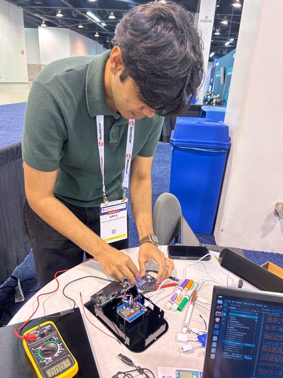
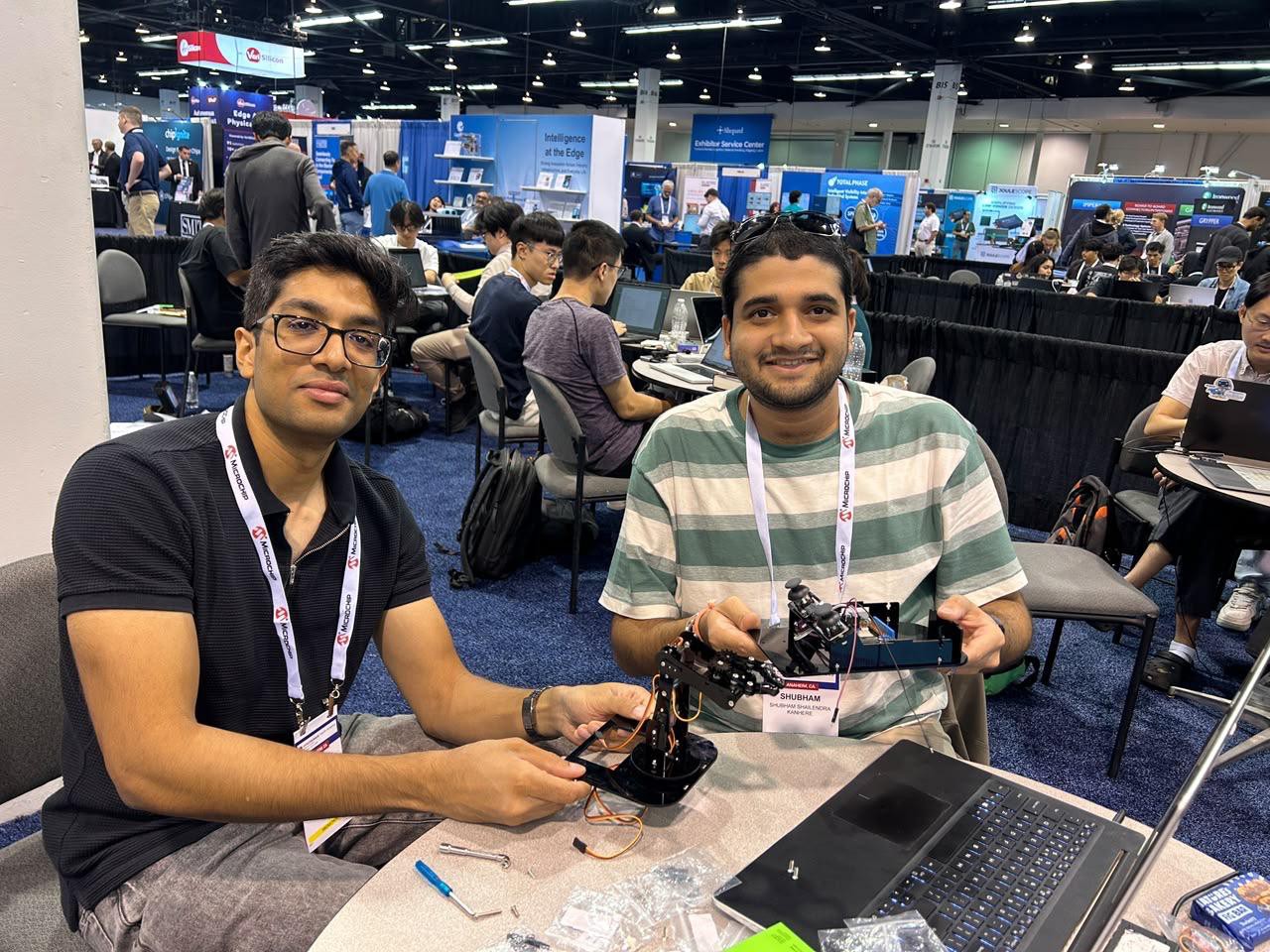
2 hours ago • 0 commentsWe assembled the ACEBOTT QD022 4-DOF arm kit following the manufacturer's video (Instruction 1). The parts list is in components section.
The USB-C hub and power supply for the UNO Q didn't arrive until later in the day, so the organizers told teams to prototype on their laptops in the meantime.
After assembly we measured the arm, because our inverse kinematics needs exact dimensions:
- Shoulder to elbow: 78 mm
- Elbow to gripper: 50 mm
- Table to shoulder pivot: 40 mm
The arm has three positioning joints (base, shoulder, elbow) plus a gripper, with no wrist.
We then wrote ESP32 joystick firmware (teleop_test.ino) to prove the hardware worked before adding autonomy:
- Joystick centring and deadzone: On boot, the firmware averages 50 readings per axis to find each stick's resting position, so the arm doesn't drift.
- Speed limit: Every joint moves at a capped rate. We first used 90°/s, but the arm was jerky, so we lowered it to 30°/s.
- Pose memory: When the arm stops moving for 1 second, the pose is saved to flash. On the next boot the arm eases back from there instead of snapping.
- Freeze button: Pressing the J1 button freezes all motion. This became the basis for our manual-override kill switch.
- End-stop warning: The firmware warns when a joint sits at 0° or 180°, where the servos buzz and heat up.
Problems we hit:
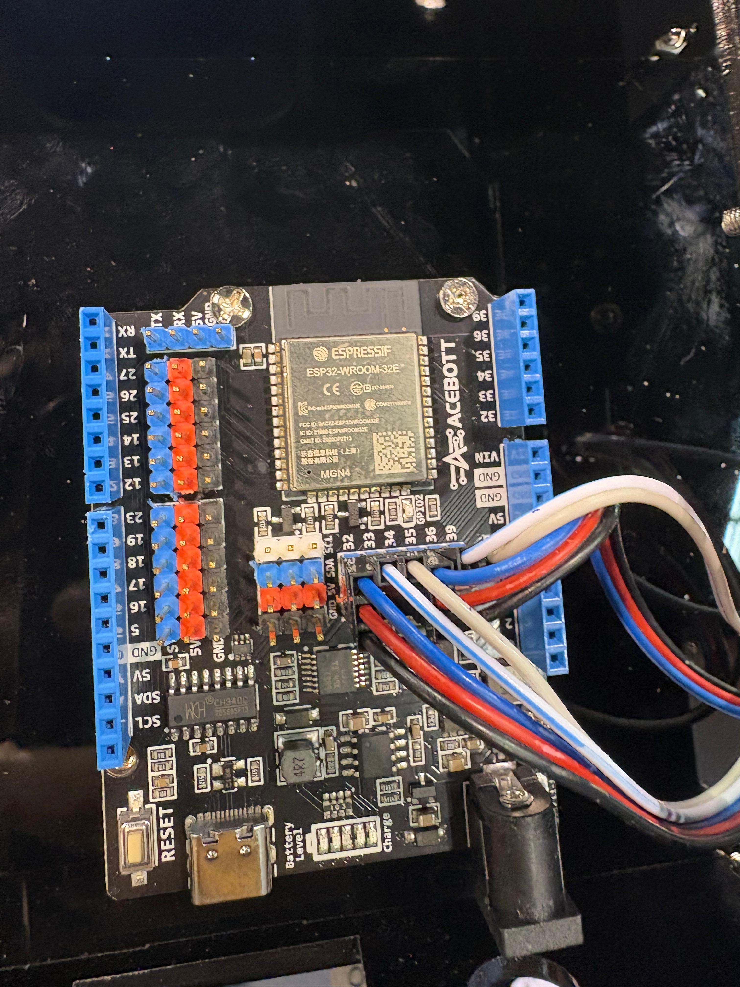
Buttons with no pull-up. ESP32 pins GPIO34/35/36/39 are input-only and have no internal pull-up resistor. Our joystick buttons read correctly only because the modules supply their own.
Reset on connect. The ESP32 resets whenever the serial port opens, so the Python side waits 2 seconds before sending any command.
Late supplies. Delays cost every team time on Day 1. The organizers let us take the arm home overnight, and implemented the changes based on updated requirements.![]()
![]()
![]()
-
Day 1 Morning/Early Afternoon: Understanding the Challenge and Planning the Control Flow
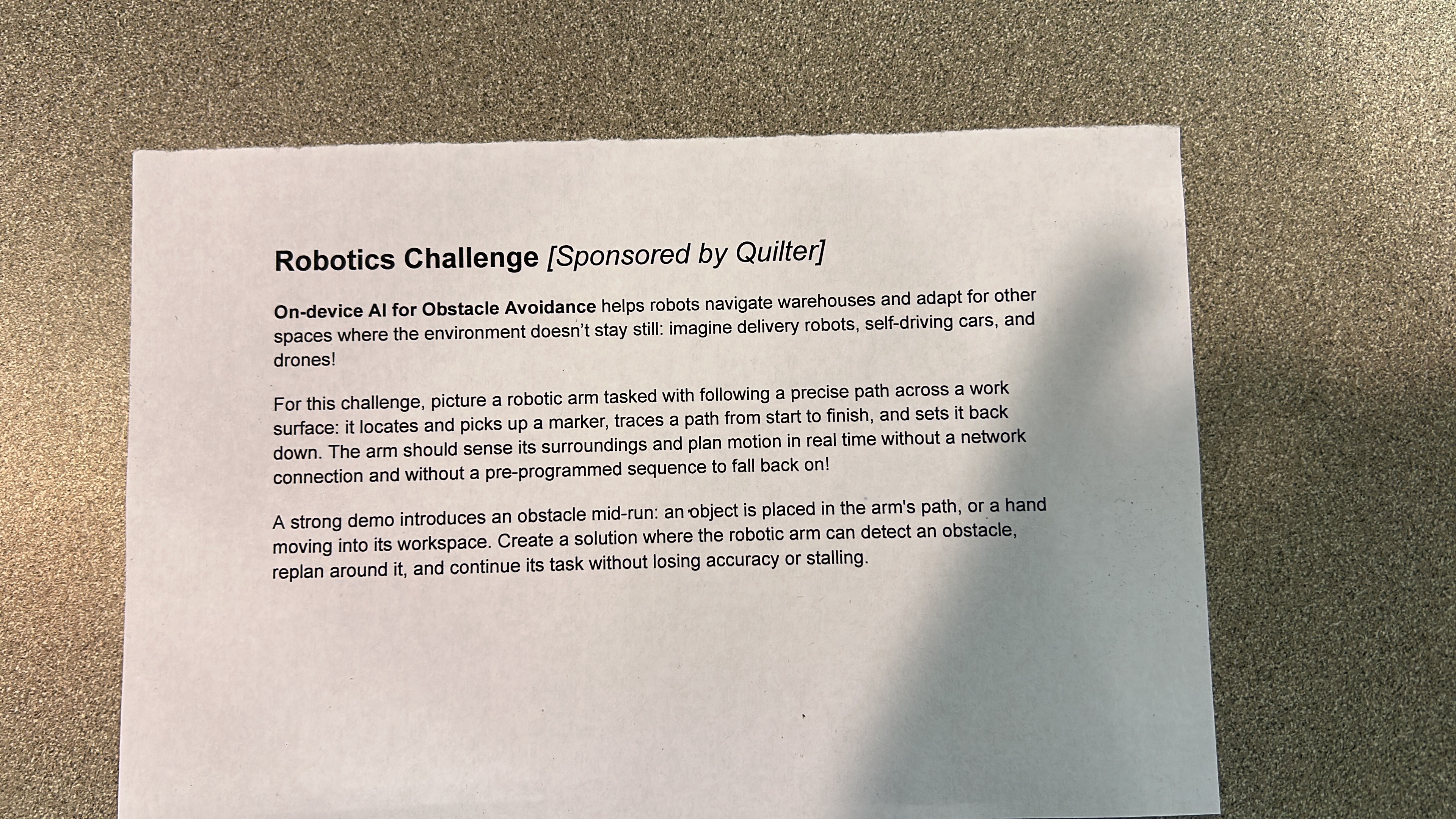
3 hours ago • 0 commentsThe challenge was handed out (first attached image) Tuesday (09/22/2026) morning 11:05 am. A robotic arm has to find and pick up a marker, trace a path from start to finish, and put the marker back down. It must plan its motion in real time with no network connection and no pre-programmed sequence. The strongest demos add an obstacle or a hand mid-run, and the arm has to detect it, replan around it, and keep going without losing accuracy.
Before touching hardware, we sketched the task as a flowchart (second attachment): find marker, pick it up, go to the path start, follow the path, put the marker back, return home. Our first key design decision came from that sketch. Our first draft had separate "find another path" boxes for the approach and for tracing. We merged them into one shared routine called Guarded Move. It moves in small steps, checks the camera before each step, and detours if something is in the way. Every movement the arm makes uses this one loop.
Our first key decision came while drawing it. The first sketch had two separate "think of another path" boxes, one for the approach and one for tracing. We merged them into a single shared routine called Guarded Move. It moves in small steps, checks the camera before every step, and detours if something is in the way. Every movement of the arm uses this one loop, so obstacle handling works the same way in every phase of the task.
![]()
![]()