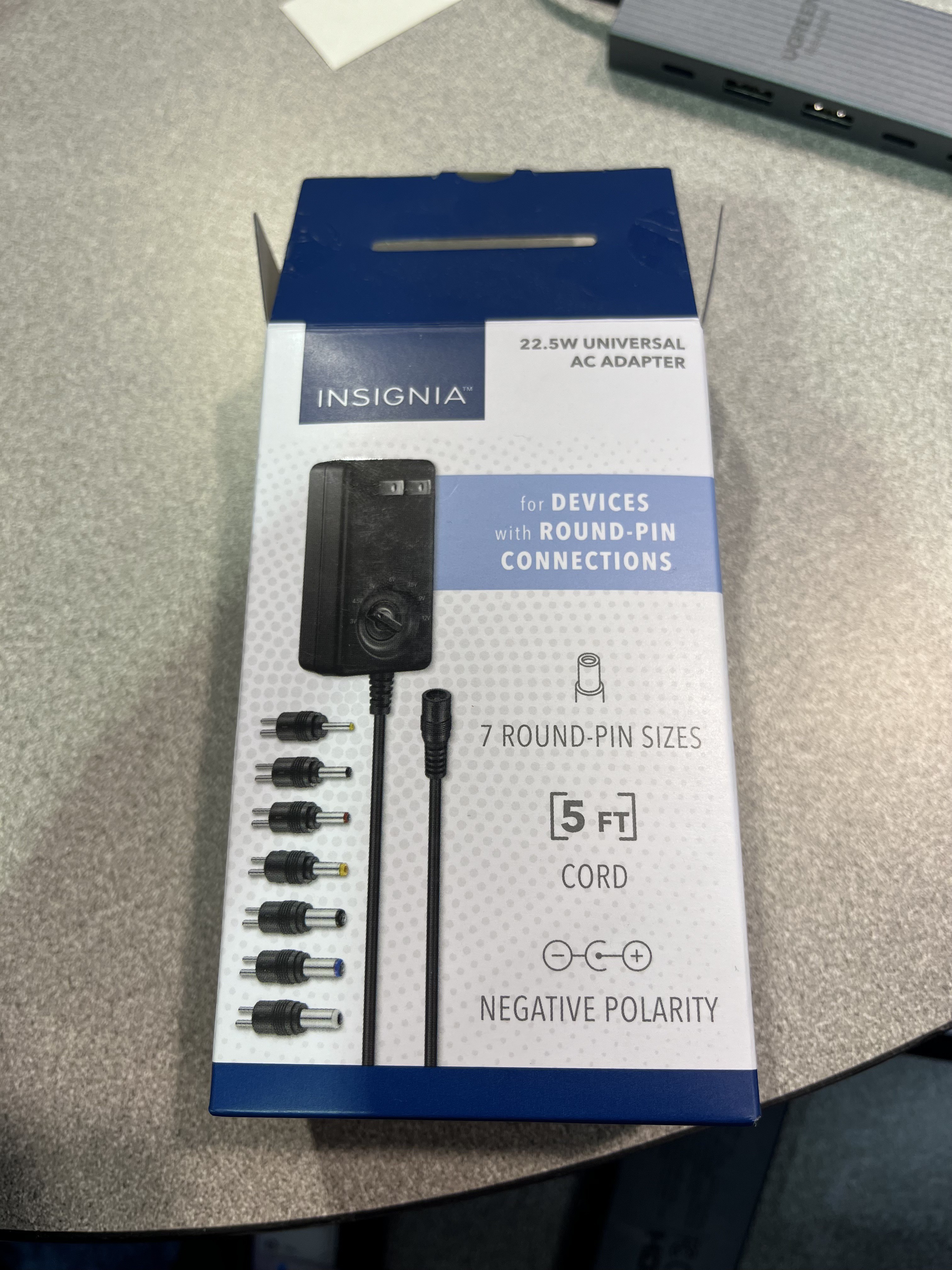
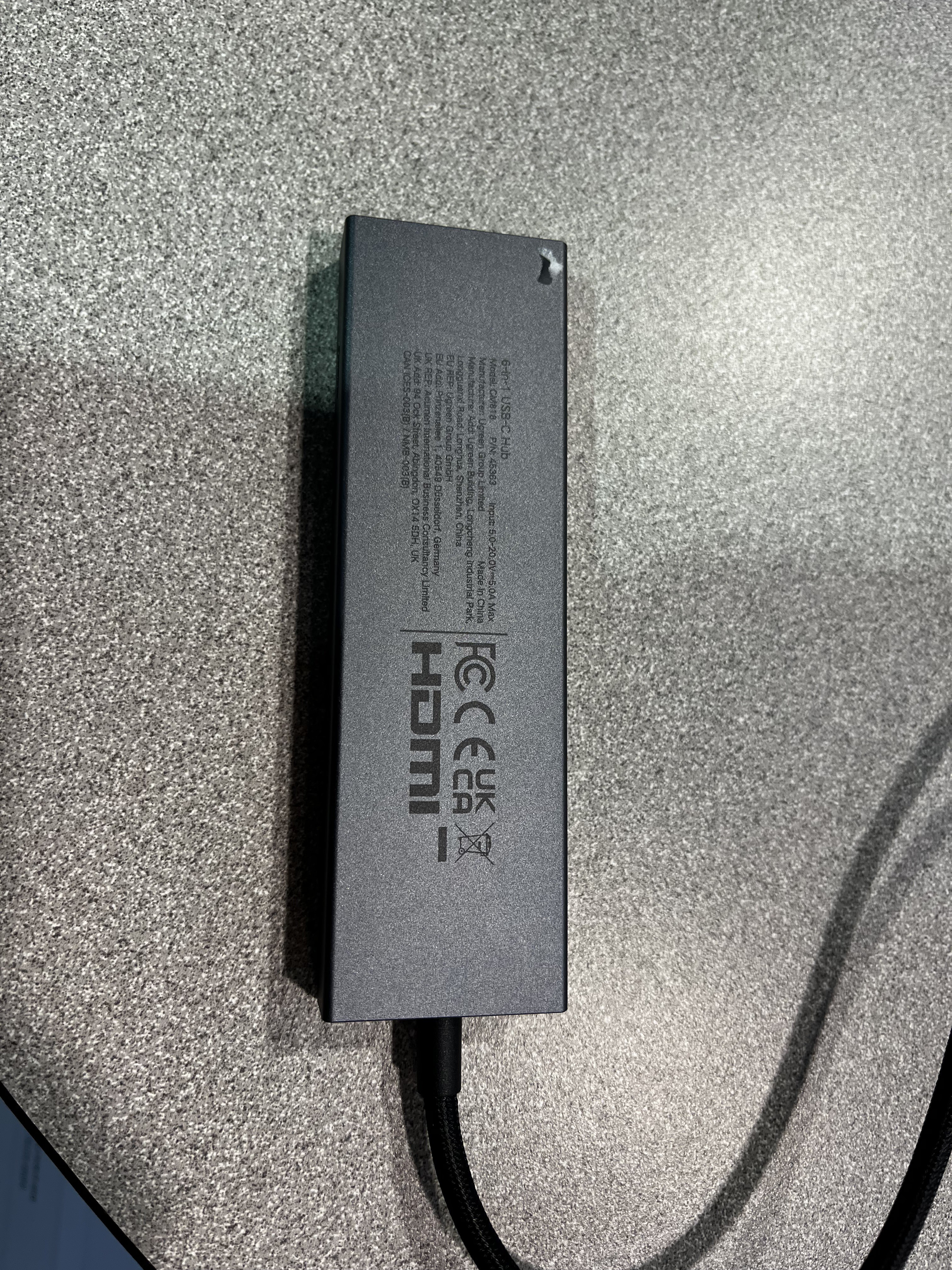
Early this morning, on the second and final day of the hackathon, the organisers brought us the AC power adapter and USB-C hub, and it made a huge difference. The organisers have been helpful and resourceful the whole way through. Whenever we asked for something, they stepped in right away to help us find a solution.
We needed the AC adapter because the 18650 batteries couldn't hold their charge long enough for what our arm needs. Four servo motors moving together draw a lot of power, especially when the arm is lifting, reaching and gripping at the same time. Batteries work well for small tinkering tasks, but a project this demanding needs a steady, reliable supply. With the adapter plugged in, the arm now runs consistently, without the jitter and slowdowns we'd been seeing as the batteries drained.
Getting here took a lot of tinkering and troubleshooting, but that's what building something complex is like. Every small roadblock we cleared felt like a big win, and when the arm finally moved smoothly on steady power, the whole team felt the rush. It's the kind of moment that reminds you why you love building things!
AC Adapter (you need to select the round pin size depending on the ESP32 Port)
A detection model can only be as accurate as the data it learns from, so we labelled our training images ourselves. We hand-labelled more than 750 images, drawing a bounding box around each object in every frame. It took our team about 2–3 hours of careful, repetitive work, but hand-labelling meant every box sat tightly around its object. That precision is what the model needs to learn exactly where the marker is.
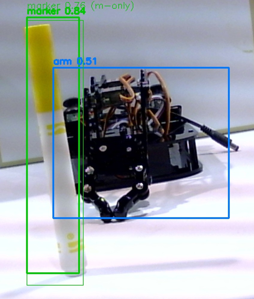
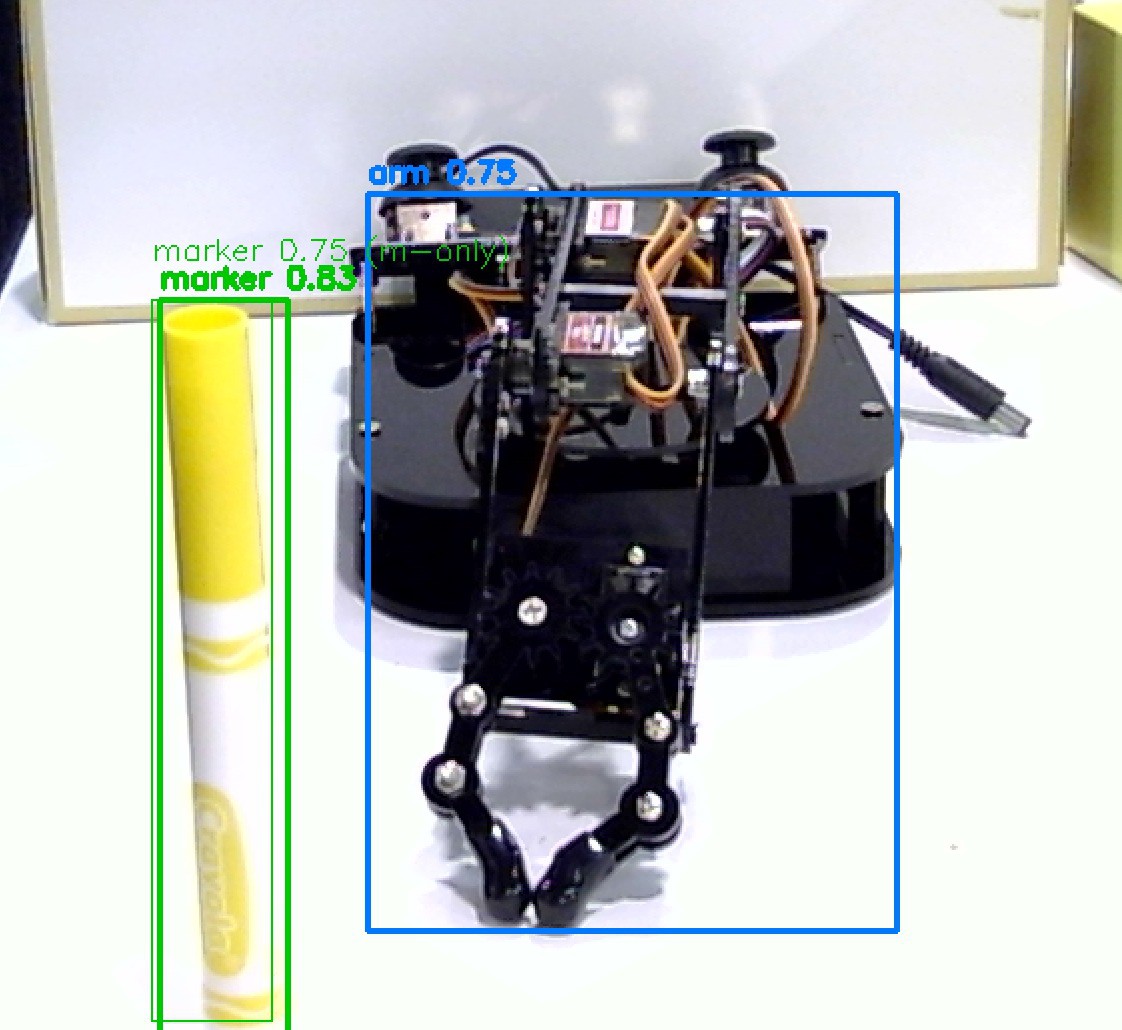
The model now detects the marker in real time and gives a confidence score for each detection, showing how sure it is that the object is a marker. It picks out the Crayola marker reliably from both a front and a side angle. It also recognises the robot arm itself, so the system can tell the marker apart from the arm reaching for it. We also compared these results with a marker-only model (the thin "m-only" boxes).
The marker is detected with 0.84 confidence and the arm with 0.51. The marker-only model finds the marker at 0.76.
The marker is detected with 0.83 confidence and the arm with 0.75. The marker-only model finds the marker at 0.75.
Day one came with a few hardware hurdles, most of them about power. The kit's battery holder takes 18650 cells, and the batteries in our box turned out to be a different size, so we couldn't power the arm at first. The organisers tracked down the right 18650s for us within a couple of hours. Chargers for them weren't available at first, though, so once the cells ran flat during testing, the arm had to sit idle. We tried connecting the board to our laptops for power but it was not enough to power all of our servo motors. This was truly a challenge for us!
The organisers have been quick and resourceful throughout. They've sourced replacement parts, checked in with teams regularly, and arranged USB hubs and extra power options to keep everyone moving. So we were relieved and grateful when they let teams take their builds home overnight. The extra time means we can charge the batteries, finish the wiring and keep working on the software, and be ready to test at full power in the morning.
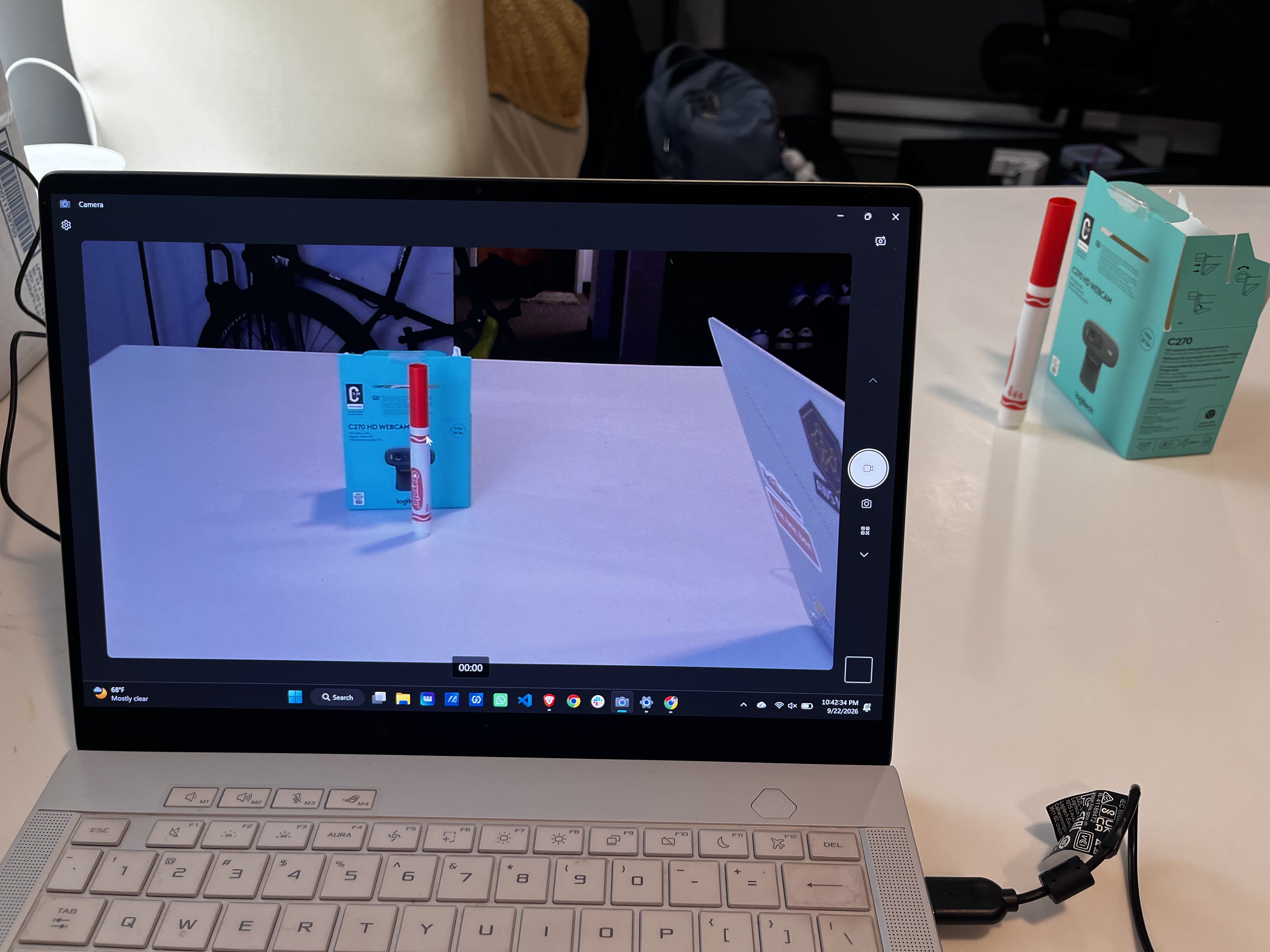
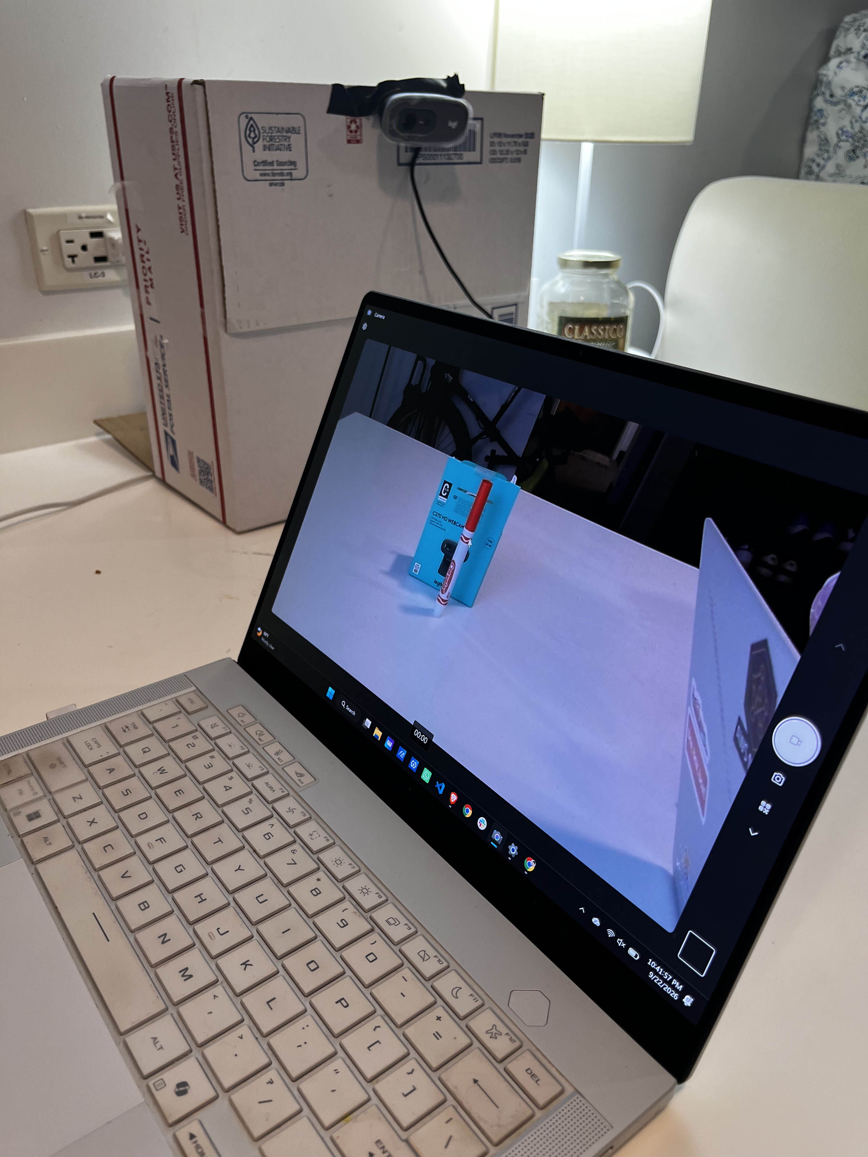
With the arm assembled, our next job was giving it eyes. We set up the Logitech C270 webcam, taped to a cardboard box as a quick mount, and tested it on a laptop to check the view before moving everything onto the Arduino UNO Q. Our test scene was a white surface with our red Crayola marker standing upright and the webcam's own box as a stand-in obstacle.
Our quick camera mount: the C270 webcam taped to a cardboard box to hold it steady while we collect training images.Live feed from the C270 during testing: the red Crayola marker stands upright, with the webcam's box as a stand-in obstacle.
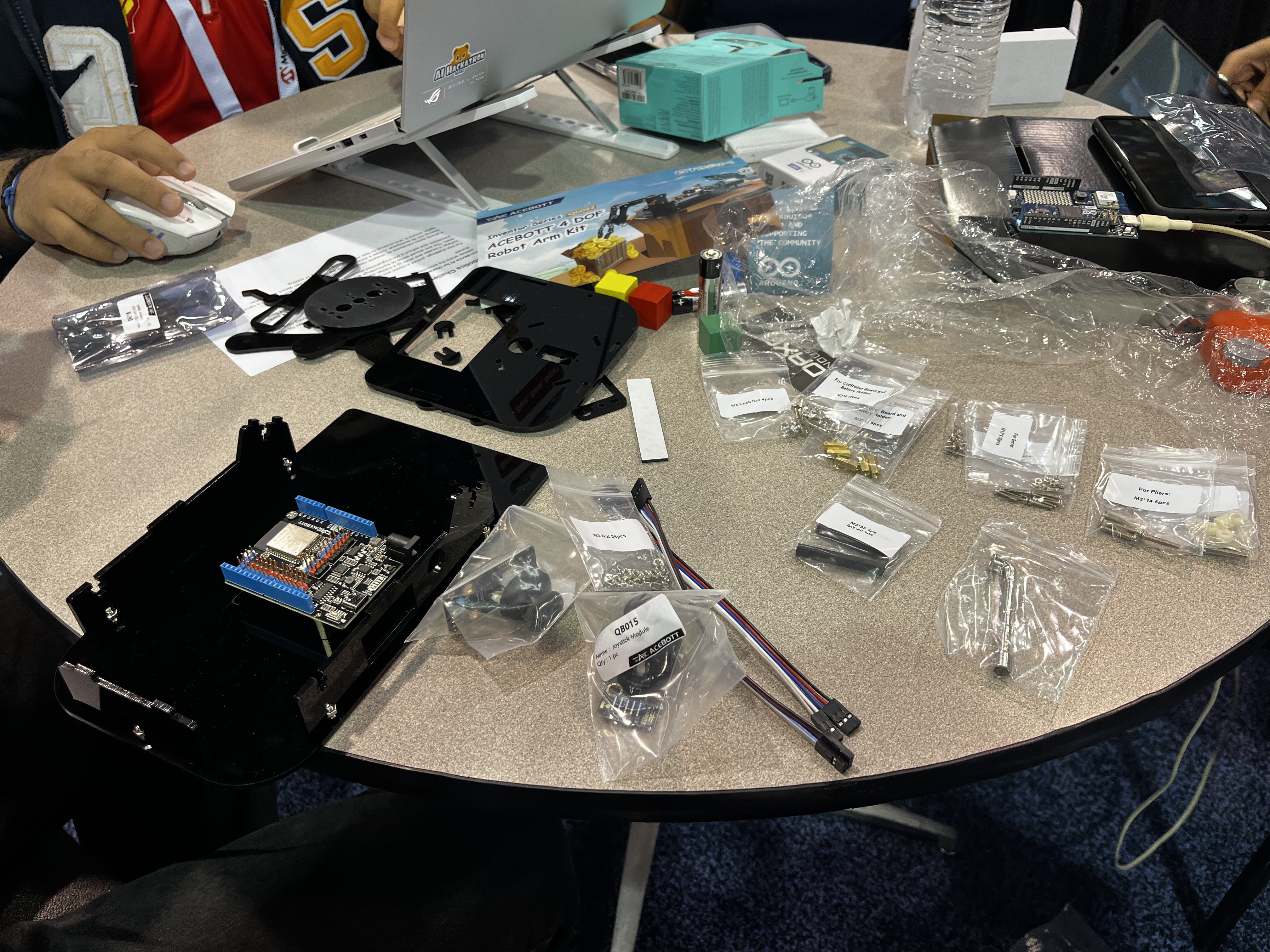
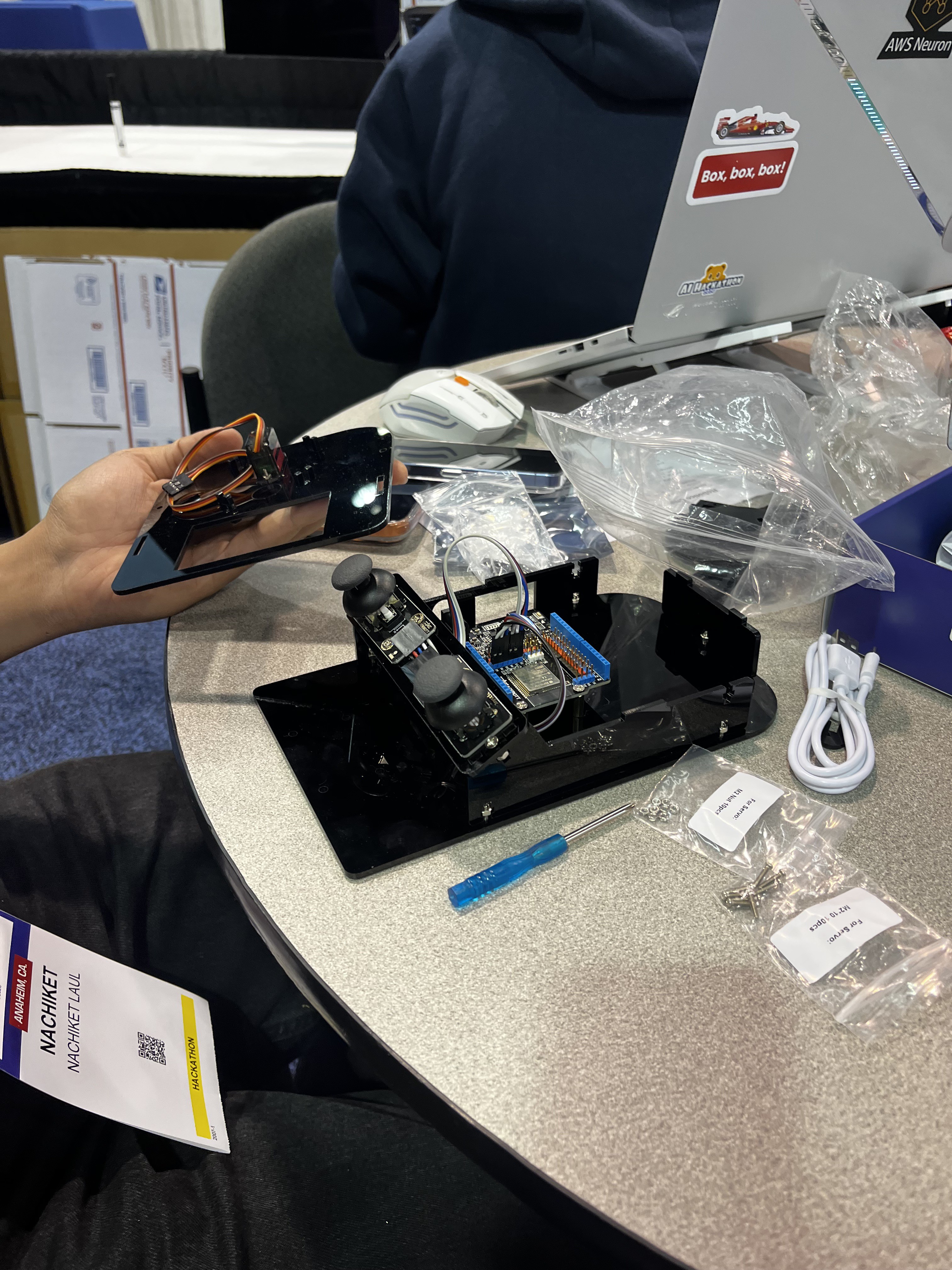
While the space was a little cramped up, we tried to lay out all of our components and assembled everything together while our other team members tried to figure out how to best make use of the Arduino Uno Q's AI capabilities for object detection and subsequent obstacle avoidance.
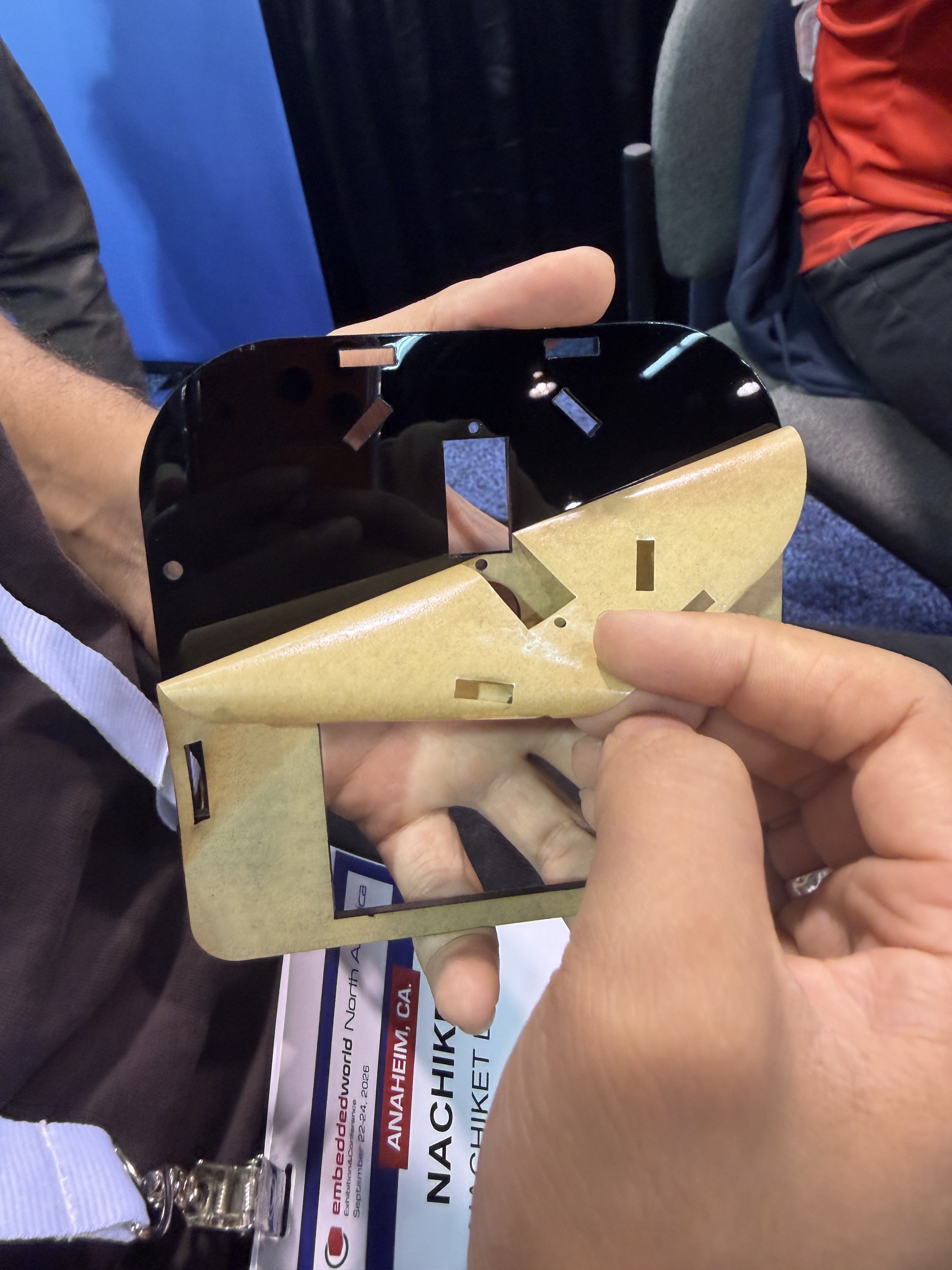
We meticulously peeled out the protective covering for all the parts of the arm.
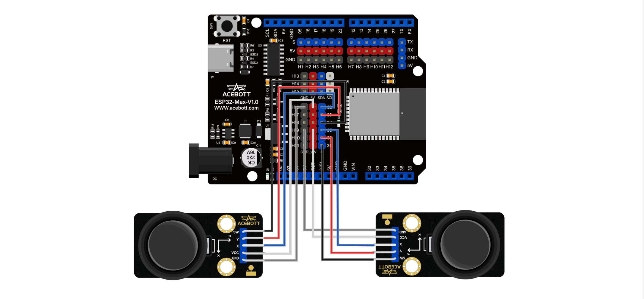
Putting all the wires together! Making sure we connect the right colored wires to their designated pins both on the components as well as the ESP32.
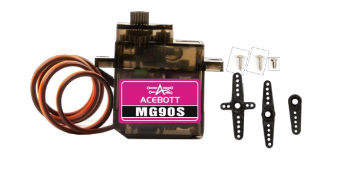
We tested the servo motors one by one, as it was mentioned in the documentation, to check each one before assembling it onto the robotic arm structure, we made sure they were initialised at the proper position so that any further steps or any untoward movement wouldn't cause any wear or damage to the motors.
For initial prototyping, we attached the joysticks as well so that we could test how well the robotic arm was able to move around.
These were the wiring we followed for the joysticks accessories.
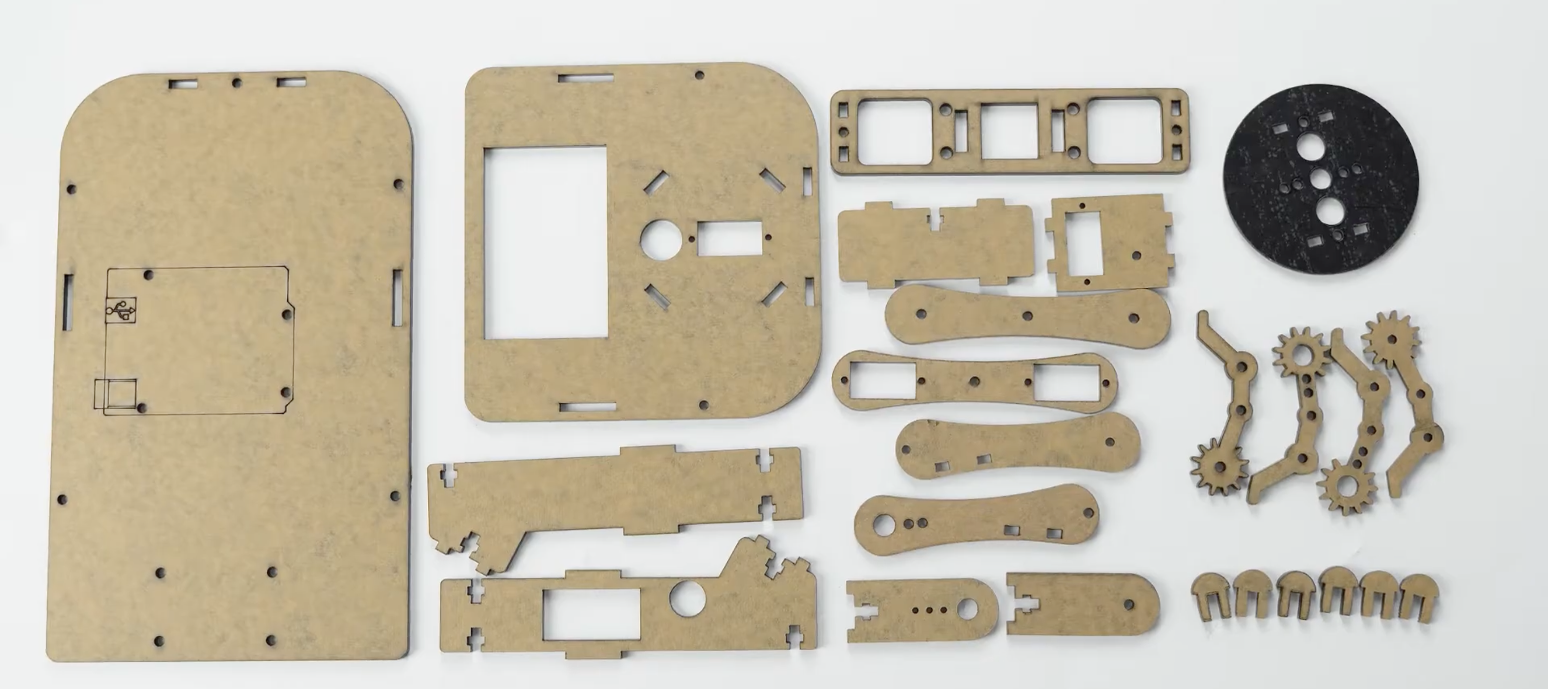
Before we could teach the arm to see, trace or dodge anything, we had to build it. The ACEBOTT QD022 kit arrives as a bag of laser-cut acrylic panels, four MG90 servos and a lot of small screws and nuts. A big chunk of our first day was spent on turning the components from that kit into a working arm.
What we followed
We used ACEBOTT's official assembly tutorial for the QD022.
It's beginner-friendly with each step showing exactly which panel and which screws to use. If you're building one yourself, we'd recommend following it step by step.
What we learned (tips for beginners)
Set the servos to their centre position before attaching the servo horns. If you skip it, a joint can end up at the edge of its range and won't be able to move fully one way.
Don't overtighten screws into the acrylic since it cracks easily. Tighten until snug, then stop.
Peel off the protective film on the acrylic panels before assembling. It's much harder to remove afterwards.
Check that every joint moves freely before moving on. A joint that's too tight makes the small servos strain, jitter and heat up.
Label the servo cables (base, shoulder, elbow, gripper) as you go. You'll need to know which is which when you wire them up and write code.
Result
By the end of this step we had a fully assembled arm that moved on all four joints when tested with the kit's joystick module.
 Shubhan Mital