Tony E. Nazzal
-
follow and like the new 3D AR glasses project.
05/18/2017 at 06:53 • 0 comments -
New micro display modules
09/07/2016 at 18:29 • 0 comments![]()
New micro display modules have shown up on Amazon and Ebay. These look ideal for a wearable computer.
Specification:
Display: ONE TFT LCD display chips
Resolution: 640×480 (WQVGA)
Screen Ratio: 16:9
Color Depth: 24-bit input
Viewing Angle: 26° diagonal
Image Input: Composite AV/CVBS
Video Signal: NTSC/PAL/SECAM automatic selection
Working voltage 3.7-5V
Working current 120MA
Power consumption 0.6W
Supported formats "8-bit RGB-serial data,Hd,Vd,Valid,Clock
CCIR 601, CCIR656"
Display frame frequency 120HZ(NTSC),100HZ(PAL)
Viewing Angle 26
An exit pupil distance 20mm
An exit pupil diameter 1-2m
AV input P/N -
Bluethooth head mounted display prototype V2.0
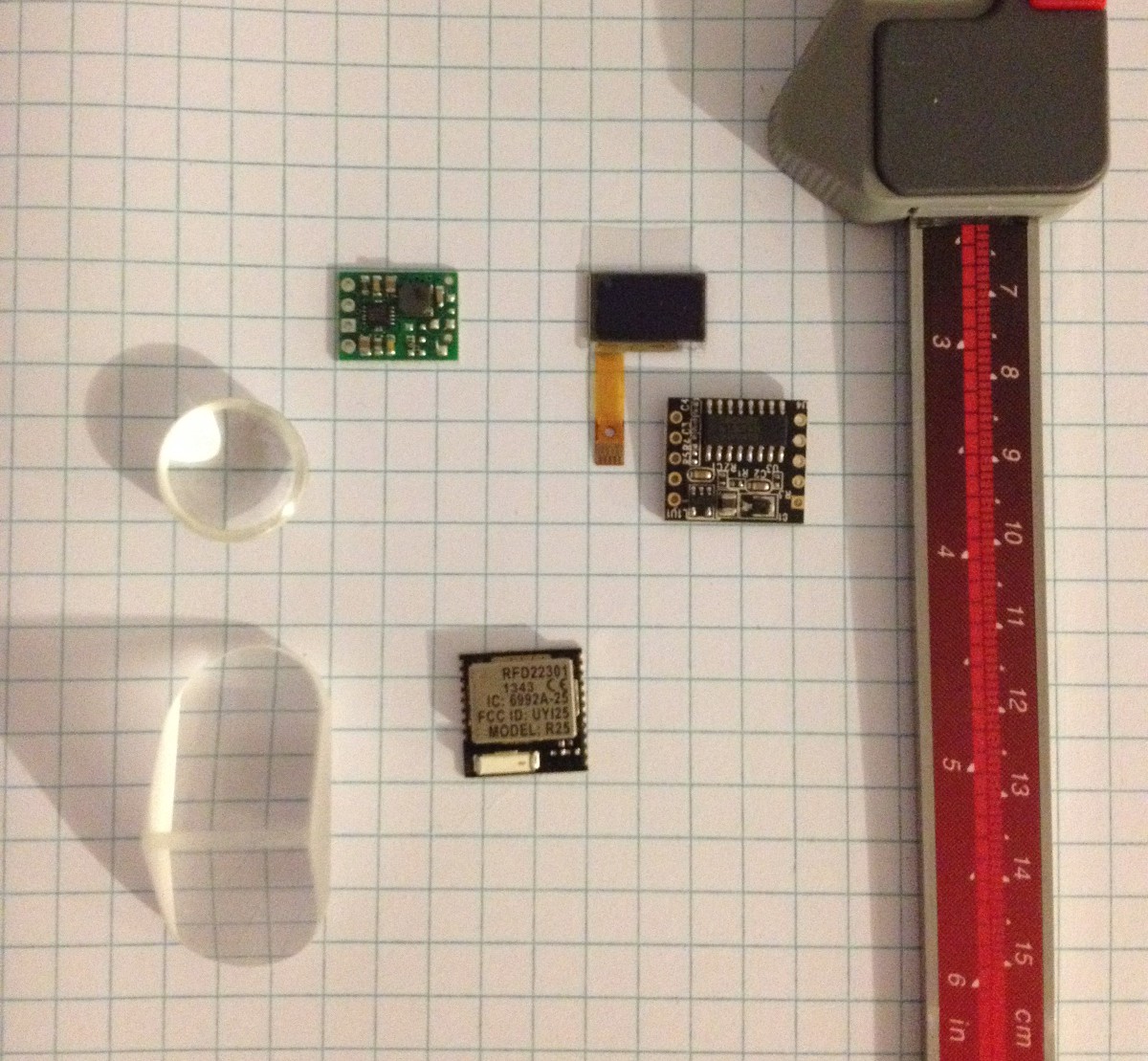
03/16/2015 at 01:15 • 2 commentsI'm working on a new prototype with smaller off the shelf components. This version will include a very tiny 10x16mm OLED display, RFDuino BLE 4.0, pololu 3.3v step-up voltage regulator, and optics components from anchor optics. Each component is much smaller than the first version. I'm attempting to reduce the size and weight of the optics with this version also. Please message me if anyone has ideas for improving the projection method.
![]()
-
gschem symbols on github
09/25/2014 at 02:25 • 0 commentsThe gschem symbols for this project have been uploaded to github.
https://github.com/HMD1/BluetoothHMD/commit/8bbf8dcfa42e89caa665b1e9041f179a6df23c8d
-
Example Code uploaded to Github
08/19/2014 at 03:00 • 0 commentsThe example code has been uploaded to github under the MIT Open Source License. These examples demonstrate basic functions of the HMD, text, led control, and sound. There is a routine in the android example that mirrors the text to make it appear correct in the eyepiece. Please comment if anyone has questions or problems with the example code.
https://github.com/HMD1/BluetoothHMD
-
Optics
07/30/2014 at 05:37 • 1 comment![]()
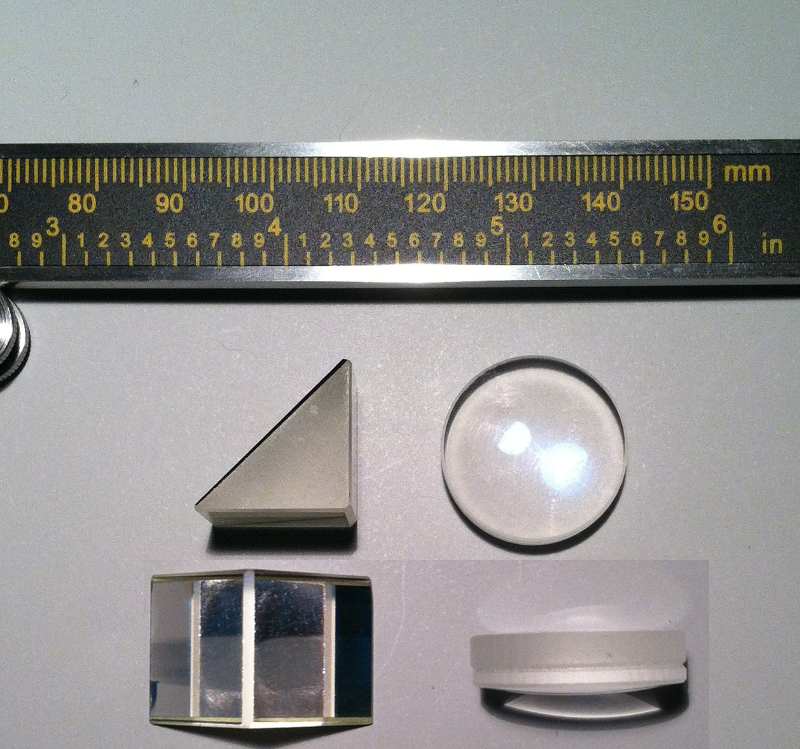
There are two main components to the HMD eyepiece. The wearer looks through a right angle prism that is 16x17mm on two sides and mirrored on the hypotenuse. The round side of the eyepiece holds a 22mm diameter plano-convex shaped lens. The prism is rotated 35 degrees to bring the viewing plane closer to the eye. The rounded side of the lens faces outward toward the OLED display and focuses perfectly on the display at 55mm from the edge of the eyepiece. The prism was obtained as part of a lot purchase on ebay, and the lens was salvaged from a little pair of binoculars. The software needs to draw to the display in reverse to make it appear correct in the eyepiece.
![]()
-
Power consumption
07/29/2014 at 04:00 • 0 comments![]()
The max current draw stayed at around ~50mA when the bluetooth module is connected. 0.7Wh / (5V *.05A) = 2.8h. Assuming the power boost module is about 90% efficient, it equals about 2.52h of battery life per battery. The glasses can also be powered over USB using a portable battery pack.
-
STL 3D files uploaded to Thingiverse
07/26/2014 at 23:35 • 0 comments![]()
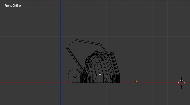
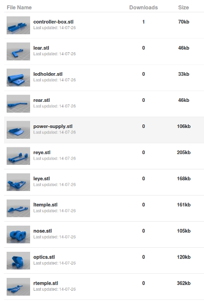
The files used by most 3d printers have been uploaded to thingiverse at (http://www.thingiverse.com/thing:408099/#files). The files were exported from blender format to stl. Please message me if anyone needs the original blender project files. I used Slic3r version 1.1.6 to generate gcode from these files, and Repetier-Host 0.85c to load the gcode and print these on my Solidoodle 2.
-
System Design creation using DIA
07/26/2014 at 20:35 • 0 comments![]()
DIA is a free program used to draw diagrams. It is a versatile program that can create many types of structured diagrams. To create the diagram I simply opened DIA and added a few box shapes from the flowchart section. I then named the boxes with the top level components of my system. The last step is to connect the diagram components using arrow lines. Finally, I saved my diagram and exported it to an image ready to upload. More information about this software can be found on the DIA home page (https://wiki.gnome.org/Apps/Dia).
-
Project schematic created using gschem
07/26/2014 at 17:55 • 0 comments![]()
gschem is a free schematics editor and is part of the gEDA project. I found gschem fairly intuitive and easy to use. The first thing I did was to create the custom symbols for my components and add them to the gchem config file. After the components were created and loaded, I simply added them to the project and connected the pins.
More information can be found on the gEDA wiki: http://wiki.geda-project.org/geda:gschem_symbol_creation
$60 bluetooth head mounted display.
The HMD is bluetooth enabled and compatible with both Linux and Android.