S.I.
S.I.-
I Saw a Real Superconducting Quantum Computer Chip
4 hours ago • 0 commentsHi everyone! I’m a KOSEN student building a DIY EFNMR Quantum Computer.
In this log, I want to take a quick break from our DIY hardware to share a personal story about the time I visited the National Museum of Emerging Science and Innovation (Miraikan) in Tokyo to see a real superconducting quantum computer chip on display.
My Trip to the Miraikan
"Under Maintenance!?"
Right after graduating from middle school, during my spring break, I had some free time. I had been wanting to see a real quantum computer chip for a long time, so I went to the Miraikan. The moment I arrived, I made a beeline for the quantum computer exhibit. However, right where the chip was supposed to be displayed, there was a sign that said, "Under Maintenance." I was honestly a bit heartbroken.
Despite that, the rest of the exhibits at the Miraikan were incredibly fascinating. Even without seeing the quantum chip, I ended up staying there all day, from opening until closing time! The highlight of that trip was the dome theater showing a movie called "The Man from the 9 Dimensions," which was an amazing visual exploration of Superstring Theory.
Finally Seeing the Chip!
Fast forward to this summer break: I went back to the Miraikan for my revenge (?). Just like last time, I headed straight for the quantum exhibit. And this time... the chip was actually there!
I was incredibly excited to finally see the superconducting quantum chip I had been dreaming about. My first impression upon seeing the real thing? It was much smaller than I expected! I had always imagined it would be around 5cm square, but it was actually only about 3cm square.
By the way, I watched "The Man from the 9 Dimensions" again on this trip! I went on a weekday afternoon in September, and it was surprisingly crowded (maybe because the museum is about to close for a 6-month renovation?). Seeing the real hardware up close gave me a huge boost of motivation to keep working on my own DIY quantum computer on my desk!
Follow Our Journey!
- Real-time updates on X (Twitter): https://x.com/nmrqcproject
- Detailed development logs and source code on GitHub: https://github.com/nmrqcproject/nmr-qc-project/blob/main/README.md
- Detailed development logs in Japanese / 日本語での詳しい開発記録 (Zenn): https://zenn.dev/nmrqcp
-
Noise Reduction Strategies
4 hours ago • 0 commentsHi everyone! I’m a KOSEN student building a DIY EFNMR Quantum Computer.
In this log, I want to share the 7 hardware upgrades and noise reduction strategies we are planning to implement next in order to clean up our FID signal.
1. Sealing the Aluminum Shielding Enclosure
Currently, because we have cables running in and out of the aluminum case, we can't close the lid completely. Environmental noise is leaking through this gap. The best solution is to drill small, exact-sized holes in the enclosure for the cables to pass through. Drilling is a bit of a last resort because it's difficult, but it's the most effective way. Another option is sealing the gap with aluminum tape, but peeling it off every time we need to tweak the circuit would be a nightmare.
2. Migrating the Amp from Breadboard to Perfboard
Right now, our ultra-low noise amplifier circuit is built on a breadboard. However, the breadboard itself acts as a giant antenna, picking up noise and feeding it straight into the op-amp. To fix this, we will permanently solder the amp circuit onto a universal PCB (perfboard).
3. Adding an Analog High-Pass Filter (HPF)
We plan to physically filter out low-frequency environmental noise before it even reaches the ADC. We will build an analog High-Pass Filter (HPF) using film capacitors and resistors directly into the amplifier circuit.
4. Coaxial Shielding for the Coil-to-Amp Connection
We are currently using standard jumper wires to transmit the microscopic signal from the sensor coil to the amplifier. We will replace these jumpers with shielded coaxial cables to block electromagnetic interference (EMI) during signal transmission.
5. Twisting the Polarization Battery Cables
The thick cables running from the 12V lead-acid battery to the polarizing coil are currently just bundled together. When a massive current flows, they generate their own magnetic field, causing internal noise. We will twist the positive and negative cables together (creating a twisted pair) to cancel out the emitted magnetic fields.
6. Adding a Relay to the Polarization Circuit
Currently, the high-current polarization circuit is controlled solely by a MOSFET. By integrating a mechanical relay into the circuit, we will be able to physically isolate and disconnect the polarization circuit from the amplifier during the highly sensitive receiving phase.
7. Changing the Measurement Location (Going Outdoors!)
For our recent successful FID observation, we measured in a room with relatively stable magnetic fields. However, a room is still inside a building—surrounded by rebar concrete and electronic devices emitting noise. To eliminate these sources entirely, we plan to pack up the system and run the experiment outdoors in a wide-open park!
Personal Note: The Real Fun Begins!
Now that we’ve entered the noise-reduction phase, this project feels more like real quantum computing than ever! Noise is one of the biggest hurdles in cutting-edge quantum computer development right now. This is where the real struggle—and the real fun—lies. To achieve my dream of becoming a quantum hardware developer, I am going to grind through these noise countermeasures and level up my engineering skills!
Follow Our Journey!
- Real-time updates on X (Twitter): https://x.com/nmrqcproject
- Detailed development logs and source code on GitHub: https://github.com/nmrqcproject/nmr-qc-project/blob/main/README.md
- Detailed development logs in Japanese / 日本語での詳しい開発記録 (Zenn): https://zenn.dev/nmrqcp
-
Our Concept and Our Catchphrase.
4 hours ago • 0 commentsHi everyone! I’m a KOSEN student building a DIY EFNMR Quantum Computer.
In this log, I want to share the origin of our project name, the meaning behind our logo, our core concept, and our newly created catchphrase.
Origin of the Project Name
NMRQCP
This is both my profile name and the official name of our DIY quantum computer project. NMRQCP comes from the initials of "Earth's Field Nuclear Magnetic Resonance Quantum Computer" (EFNMRQC). Since EFNMRQC was a bit too long, we dropped the "EF" to make it NMRQC, and added a "P" for Project—resulting in NMRQCP.
What Our Logo Represents
![NMRQCP Logo]()
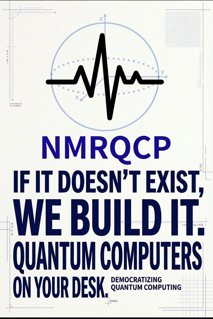
This is the official logo of our project. The Bloch sphere in the background represents quantum computing and the manipulation of quantum states, while the waveform in the foreground represents the actual NMR signal (FID wave) that we capture and read with our EFNMRQC hardware.
Project Concept
Democratizing Quantum Computing
This is the core concept driving our project. Right now, actual quantum computer hardware is locked behind closed doors—accessible only to massive corporations, research institutes, and universities. Our mission is to change that and make quantum hardware accessible to anyone.
By developing a low-cost, easy-to-build quantum computer and open-sourcing all of the designs and code online, I want to help build a society where anyone can get hands-on experience with quantum hardware—a truly democratized quantum future.
(If you want to read more about why I want to make this accessible to everyone and how I first got into quantum mechanics, check out our project details or this article (in Japanese).)
Our Catchphrase
"If it doesn't exist, we build it. Quantum Computers on your desk."
The first half—"If it doesn't exist, we build it"—comes from my lifelong maker motto. I desperately wanted to touch and tinker with quantum computer hardware, but had zero access to it. This project was born out of that exact frustration: if there's no way for me to touch one, I'll just build one myself.
The second half—"Quantum Computers on your desk"—captures the exact defining feature of this project: creating a quantum computer compact and accessible enough that anyone can build and run it right on their own desktop.
![]()
Follow Our Journey!
- Real-time updates on X (Twitter): https://x.com/nmrqcproject
- Detailed development logs and source code on GitHub: https://github.com/nmrqcproject/nmr-qc-project/blob/main/README.md
- Detailed development logs in Japanese / 日本語での詳しい開発記録 (Zenn): https://zenn.dev/nmrqcp
-
Observing the FID Signal!
4 hours ago • 0 commentsHi everyone! I’m a KOSEN student building a DIY EFNMR Quantum Computer.
In this latest experiment, we finally succeeded in capturing the FID signal (damped sine wave)!
Observing the FID Signal!
![Observed FID Signal and FFT Peak]()
First, the FID signal of hydrogen atoms (protons) in the Earth's magnetic field occurs at a frequency right around 2000Hz to 2100Hz.
If you look at the bottom graph in the photo, right around the purple dot between 2000Hz and 2100Hz, there is a distinct, sharp peak. This is the exact FID signal we’ve been hunting for!
However, looking at the top time-domain graph, you can't really see a clear damped sine wave. We believe this is because a massive dead time is occurring in the green section due to residual surge current from the coil switching.
This also explains why the peak around 2000Hz–2100Hz is relatively small. Because of the dead time, we are losing the initial head of the damped sine wave where the signal amplitude is at its strongest. What the FFT graph is actually showing is the tail end of the microscopic FID signal—those tiny oscillations right after the green dead-time line drops back to zero in the top graph.
Future Challenges & Countermeasures
This experiment brought two critical hardware challenges to light:
- Due to dead time, we are missing the most crucial data right after sequence switching.
- The signal is still nearly buried in analog noise.
Personal Thoughts: A 6-Month Journey & The 0.25x Speed Discovery!
I am beyond thrilled that we finally observed the FID signal! It took us about half a year to get to this point. For six months, spending hours every single day researching, brainstorming, building, and testing has finally paid off!
This experiment was the very first time we ran all the circuits together and performed real data analysis. Funny enough, while we were running the experiment, I didn't even realize the FID signal had appeared. Because the signal flashes by in a fraction of a second, we were recording a video of the screen and playing it back at 0.5x speed—and we couldn't find anything. I thought we had failed.
However, a little while after returning to my dorm room, I uploaded the video to Google Photos and rewatched it at 0.25x speed. Suddenly, I thought, "Wait... could this be it?!" I paused the video and scrubbed through it frame-by-frame manually—and there it was: the exact frame showing the FID peak on the graph! Going from the disappointment of thinking it failed to discovering we actually caught it made me unbelievably excited.
Riding this momentum, we are going to keep tackling the dead-time and noise issues head-on and complete this DIY quantum computer!
Follow Our Journey!
- Real-time updates on X (Twitter): https://x.com/nmrqcproject
- Detailed development logs and source code on GitHub: https://github.com/nmrqcproject/nmr-qc-project/blob/main/README.md
- Detailed development logs in Japanese / 日本語での詳しい開発記録 (Zenn): https://zenn.dev/nmrqcp
-
[Archive] Project History & Early Development (Apr - Sep 2026)
4 hours ago • 0 comments💡 Archived Development Logs: This post compiles the early records of our project (Chapters 01–14). Since I didn't have time to write massive foundational articles while building the hardware in parallel, I used AI to help structure the text for these early logs. (Starting from our latest log where we successfully observed the FID signal, everything is written 100% in my own words!)
01. What is a Quantum Computer?
First, the computers inside our smartphones and PCs are called "classical computers."
Differences from Classical Computers
Simply put, quantum computers are orders of magnitude faster at specific calculations. For example, Google reported that their quantum computer (Willow) solved a calculation in 300 seconds that would take a supercomputer longer than the age of the universe (about 13.8 billion years). That makes it roughly 1.5 quadrillion times faster. However, quantum computers have strengths and weaknesses—they aren't faster at everything, and classical computers still beat them in many everyday tasks.
What Can They Do? (Present & Future)
Quantum computers excel at simulations and optimization, analyzing far more patterns than classical machines.
- Current Applications: Optimizing delivery routes and factory production lines (Japan Post, Denso), financial simulations (MUFG), exploring stable chemical structures for drug discovery (PeptiDream, Fujitsu), and elucidating chemical reaction mechanisms (Mitsubishi Chemical).
- Future Potential: Next-gen material discovery (more efficient solar panels, CO2 capture), molecular-level drug simulations with zero side effects, hyper-accurate weather forecasting, infrastructure optimization (solving traffic jams), artificial photosynthesis, breaking current cryptography (driving the shift to post-quantum cryptography), and advancing fundamental physics (I personally hope quantum simulations bring us one step closer to the "Theory of Everything").
Timeline & What Students Should Do
As of 2026, quantum computers are entering the practical phase, though still far from perfect. Near-complete machines are expected around 2030, and fault-tolerant general-purpose quantum computers around 2050. For students looking to dive in: start with an introductory book with good illustrations, attend quantum events to hear from experts in person, and try cloud quantum services like IBM Quantum to experience it firsthand!
*Note: The illustrations in Chapter 01 were generated using Gemini.
02. Starting a DIY Quantum Computer Using the Earth's Magnetic Field!
In April 2026, I officially started a personal project to build my own quantum computer! You might think a quantum computer requires a massive cryostat cooled to -273°C, but I am using a method called EFNMR (Earth's Field Nuclear Magnetic Resonance).
Using the Earth Itself as a Giant Magnet
While hospital MRIs and standard NMR machines use ultra-powerful superconducting magnets, our Earth itself is a giant magnet with a North and South pole. EFNMR uses this natural magnetic field to control nuclear spins (qubits). Because it needs no massive cooling system, you can observe and manipulate quantum mechanical phenomena right on your desk by building your own coils and circuits.
What We Are Building (Full-Scratch)
- Polarizing & Receiver Coil: Enamel wire hand-wound in many layers around a transparent PVC pipe holding a pure water sample.
- Signal Processing Circuit: A custom op-amp amplifier inside an aluminum shielding enclosure to pick up nanovolt-to-microvolt signals.
- FPGA: Dedicated digital circuitry for high-speed, precision pulse control.
- Python: FID signal analysis, noise removal, and Fast Fourier Transform (FFT).
- Power & Control: Lead-acid battery + MOSFET circuit to minimize power noise, controlled and monitored by an M5Stack.
03 & 04. Simulating NMR Signals in Python: FFT and Pulse Control
Before touching the soldering iron, let's look at how we observe and manipulate the quantum world using Python.
The Message from the Quantum World: "FID Signal" & Noise
We need to catch the extremely weak radio wave (NMR signal) emitted by nuclear spins—a smooth, periodic sine wave that decays over time, called an FID (Free Induction Decay) signal, expressed as
s(t) = A * sin(2πft) * exp(-t/T2). Here is the ideal waveform simulated in Python (NumPy & Matplotlib):![Ideal FID Waveform]()
However, in reality, cosmic noise and thermal noise from electronic circuits bury this clean signal. Adding white noise (mean 0, standard deviation 0.2) turns it into a jagged mess:
![Noisy FID Waveform]()
The Magic of "FFT" (Fast Fourier Transform)
To find the target frequency in a sea of noise, we use FFT, which acts like a prism separating light into colors. While standard Fourier Transform takes O(N²) operations, FFT reduces it to O(N log N). For real-number signals, I used complex FFT (
np.fft.rfft). While testing by mixing 2100Hz and 2150Hz waves, I also discovered that if frequencies are too close, they are hard to resolve cleanly.![FFT Result]()
How Pulse Control Manipulates Qubits
- Identify the resonant frequency (Hz) of the qubit using FFT.
- Fire a manipulation pulse (radio wave) at that exact Hz toward the qubit.
- The atom absorbs energy ("resonance"), and the spin direction changes.
- Analyze the resulting FID signal with FFT after the pulse ends.
If there is no FFT peak, the state is
|0⟩; if there is a peak, it is|1⟩(or a superposition). By adjusting the duration of this pulse, we can freely control the quantum state!
05. Learning FPGA: Where All Circuits Run Simultaneously!
To generate ultra-precise pulses to control nuclear spins, I took on the challenge of FPGAs and Verilog HDL (Register Transfer Level / RTL).
![FPGA Board]()
Unlike standard PC programs that run sequentially line-by-line, all circuits inside an FPGA run simultaneously. To create sequential steps ("do B after A") in a concurrent world, we use:
- Clock Dividers: Counters that divide the fast base clock into slower reference clocks.
- Finite State Machines (FSM): Remembering the current state and transitioning to the next upon a trigger—essential for executing complex pulse sequences.
- NCO (Numerically Controlled Oscillator) & DDS (Direct Digital Synthesis): Calculating phase angles digitally (e.g., representing 360° as a 16-bit number) and converting those numbers into actual analog voltage waves of any target frequency.
module my_chip(
  input clk,   // Clock
  input rst_n, // Reset button
  output led
);
endmodule
06. Hand-Drawn Schematics & Dual-Layer Amplifier Protection
Here are the original hand-drawn schematics for our EFNMRQC, drafted on graph paper. CAD software is great, but nothing beats sketching on paper when brainstorming current flow and component layouts.
![Schematic 1]()
![Schematic 2]()
![Schematic 3]()
Two-Stage Protection Against High Current
During polarization, we run a massive current through the sensor coil. If that current enters the sensitive amplifier circuit, the op-amps will fry instantly. Initially, I added a Fast Recovery Diode to block current from flowing into the amp. To be 100% sure, I added a second failsafe: an M5 Relay Unit. This physically disconnects the amplifier circuit while strong pulses are fired, creating a rock-solid fail-safe system.
07. Switching Circuits with M5Stack and Relays
Using an M5Stack CoreS3 Lite and a Mini Relay Unit, I wrote a basic state-machine program in Arduino IDE (using the
M5Unifiedlibrary) to safely alternate between Polarization and Receiving phases.![M5Stack and Relay]()
// --- 1. Polarization Phase ---
digitalWrite(RELAY_PIN, LOW); // Relay OFF
M5.Display.println("1. Polarizing...");
M5.Display.println("Relay: OFF (Charge)");
delay(5000); // Polarize for 5 seconds

// --- 2. Receiving Phase ---
digitalWrite(RELAY_PIN, HIGH); // Relay ON
M5.Display.println("2. Receiving...");
M5.Display.println("Relay: ON (Listen)");
delay(3000); // Listen for signal for 3 seconds
08. High-Current Switching Circuit Test
To prevent power supply noise from wall outlets, our main polarization power source is a 12V sealed lead-acid battery (12V12Ah WP12-12). Since the M5Stack only outputs 3.3V signals, connecting it directly would destroy the microcontroller. I designed a drive circuit using an N-ch Power MOSFET (Toshiba 2SK4017(Q), 60V/5A).
![Breadboard Switching Test]()
Before connecting the massive coil, I tested the circuit on a breadboard (EIC-102BJ) with an LED dummy load and checked the switching waveform on a portable oscilloscope:
![Oscilloscope Switching Waveform]()
The rise and fall times were razor-sharp with almost zero ringing! To prepare for the massive back-EMF (surge voltage) when cutting off current to the real inductive coil, we procured a Kyocera 20NFA40 (400V/2A) Fast Recovery Diode to act as a flyback diode in parallel with the coil.
09. Capturing Room Audio and Running Real-Time FFT!
To digitize the analog signals from the coil into the PC, I introduced a 96KHz / 24-bit Hi-Fi USB External Sound Card, connected via a shielded BNC cable and a BNC-to-3.5mm mono adapter.
Using
PyAudio,NumPy, andMatplotlib, I built a real-time FFT analyzer applying a Hamming window to reduce edge noise:# Execute Fast Fourier Transform (FFT) # Apply Hamming window to reduce noise at both ends window = np.hamming(CHUNK) fft_data = np.abs(np.fft.rfft(audio_data * window))![EFNMR Real-time FFT Analyzer]()
The "EFNMR Real-time FFT Analyzer" plotted the frequency spectrum! However, low-frequency environmental noise peaks showed up—the system is so sensitive it picks up voices and tiny footsteps. Absolute silence will be mandatory for our quantum experiments.
10. Soldering the PCBs (I Never Want to Do This Again!)
With breadboard verification done, we moved to soldering onto double-sided through-hole universal PCBs (B-type, 95x72mm).
1. Polarization MOSFET Board
We mounted the
2SK4017(Q)MOSFET and soldered the20NFA40flyback diode on the back with thick solder traces to handle high current. We used AWG18 UL1007 heat-resistant wire and added an inline 5A blade fuse on the positive battery terminal for short-circuit protection.2. The SMD Op-Amp Nightmare
To amplify the microscopic FID signal, we used the AD797BRZ ultra-low noise op-amp. Because it's a tiny grain-of-rice SMD chip, we had to solder it onto a SOP8-to-DIP8 adapter board.
![AD797BRZ SMD Soldering]()
Honest confession: Soldering this op-amp was pure hell. The pin pitch is microscopic. The trick was melting a tiny bit of solder on the tip and letting surface tension pull it onto the pad—otherwise, pins bridge instantly. Desoldering braid (solder wick) saved my life. I honestly never want to solder an SMD op-amp again (lol).
11. Winding 250 Meters of Enamel Wire by Hand (1,600 Turns!)
To build the sensor coil bobbin, we cut a 48mm OD transparent PVC pipe with a pipe cutter and wound 0.5mm 2UEW enamel wire around it—1,600 turns, totaling ~250 meters!
3 Survival Tips for Hand-Winding Coils:
- Tape it down frequently: If your hand slips and the wire unspools, you have to start over in despair.
- Always work in pairs: One person rotates the PVC pipe while the other keeps tension on the wire. Doing it solo is nearly impossible.
- Take breaks: Keeping constant tension exhausts your hands faster than you think.
![1600-Turn Hand-Wound Coil]()
We connected the finished coil to the MOSFET board and 12V lead-acid battery for a high-current test. Thanks to the
20NFA40flyback diode absorbing the massive inductive kickback, the MOSFET survived without a scratch!
12. Completing the Complex Analog Amplifier Circuit!
We assembled the analog receiver circuit on a breadboard around our DIP-adapted AD797BRZ op-amps, incorporating 1μF 100V metallized polyester film capacitors for coupling and noise filtering.
![Analog Amplifier Breadboard]()
When we powered it on and hooked up the portable oscilloscope, we saw a clean sine wave of Vp-p: 8.80mV!
![2.04kHz Sine Wave on Oscilloscope]()
Even more exciting: the frequency read 2.04kHz—the exact Larmor frequency band of protons in the Earth's magnetic field! This proved our amplifier could cleanly process our target frequency.
13. Full Sequence Control: The Magic 50 Milliseconds
To integrate the MOSFET polarization circuit and Op-Amp receiver circuit without frying the AD797BRZ with residual coil surge voltage, I programmed a 3-stage sequence on the M5Stack CoreS3 Lite with a critical 50ms dead-time delay:
// ==========================================
// 2. Surge Decay Phase (Dead Time) *CRITICAL*
// ==========================================
// Turn OFF MOSFET to cut current
digitalWrite(MOSFET_PIN, LOW);
M5.Display.println("2. Surge Waiting...");

// Wait for coil back-EMF to dissipate through the flyback diode
// *Without this delay, the receiver circuit will be destroyed!
delay(50);

// ==========================================
// 3. Receiving Phase (Receiving / FID)
// ==========================================
// After the surge is gone, connect the receiver circuit via relay
digitalWrite(RELAY_PIN, HIGH);
14. System Integration & Debugging Hell (Magic Smoke!)
We mounted the 1,600-turn coil, MOSFET driver, and op-amp receiver inside the aluminum enclosure and connected it to the PC via the StarTech USB sound card.
![Full System Integration in Aluminum Box]()
At first, no signal reached the PC. After hours of checking wiring and microphone permissions, the culprit was a dead 9V battery powering the op-amp. Relieved, I rushed to buy a new battery, plugged it in hurriedly, and... accidentally reversed the polarity.
A wisp of smoke rose from the ultra-low noise AD797BRZ op-amp. All that painful SMD soldering went up in smoke in a split second. Thankfully, I had a spare op-amp and repaired the circuit, vowing to always double-check polarity before applying power.
After recovery, the OS finally detected the microphone signal input! However, our Python script (
efnmr_monitor.py) still showed a flat line due to an audio device ID configuration issue—setting the stage for our next breakthrough where we finally captured the real FID signal!
Follow Our Journey!
- Real-time updates on X (Twitter): https://x.com/nmrqcproject
- Detailed development logs and source code on GitHub: https://github.com/nmrqcproject/nmr-qc-project
- Detailed development logs in Japanese / 日本語での詳しい開発記録 (Zenn): https://zenn.dev/nmrqcp
-
Building a Quantum Computer from scratch!
4 hours ago • 0 commentsHi everyone, I’m a KOSEN (National Institute of Technology in Japan) student, and together with my friends, I am building a DIY Quantum Computer using the Earth's Field Nuclear Magnetic Resonance (EFNMR) method. In this log, I’ll share the backstory of how I ended up building a quantum computer from scratch and give an overview of the project.
The Origin Story: Why I Decided to Build a Quantum Computer
My First Encounter with Quantum Mechanics and a Middle School Science Project
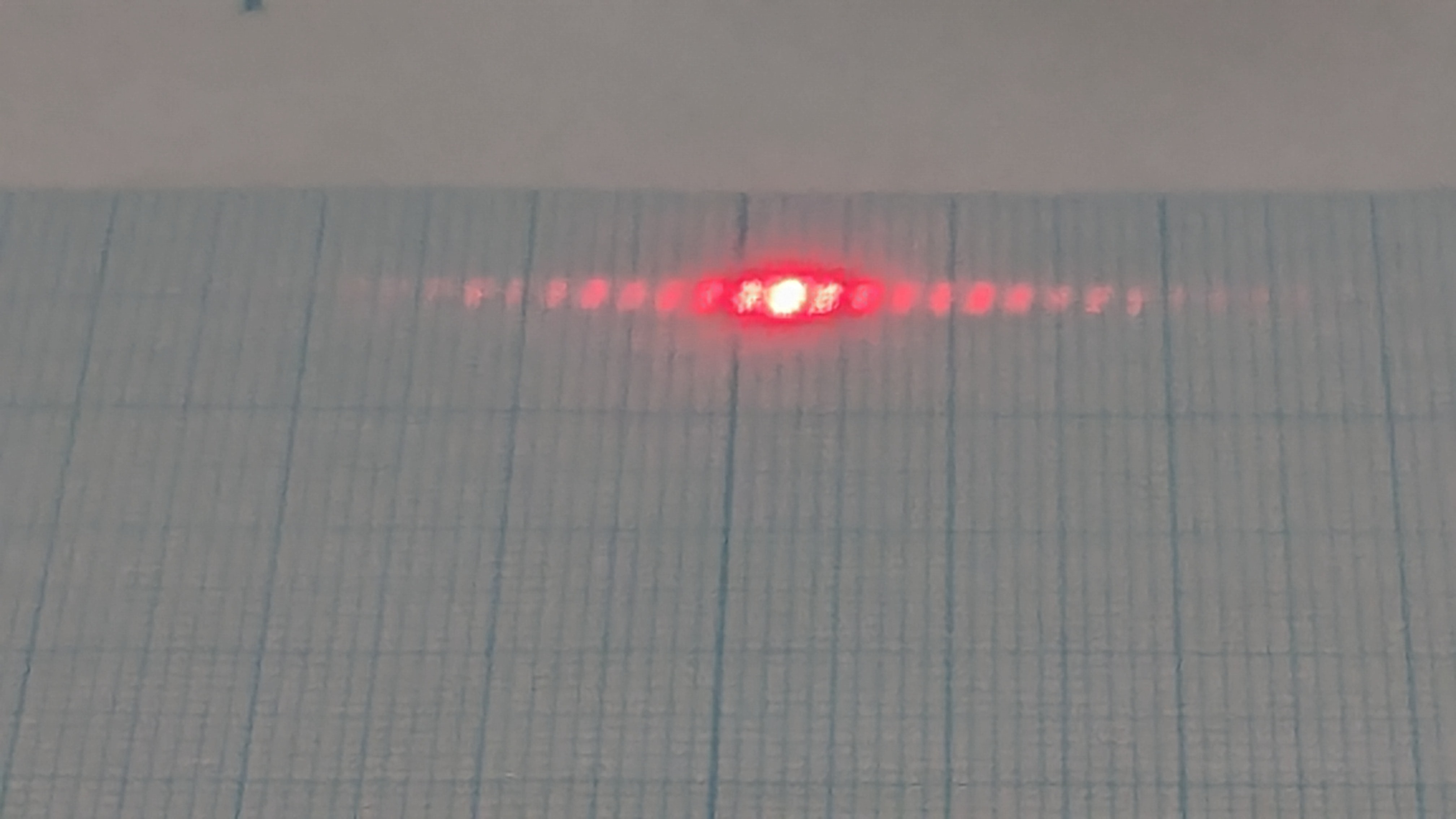
I first learned about quantum mechanics when I was in my second year of middle school (8th grade). I was immediately captivated by the fact that, despite how surreal and counterintuitive quantum theory seems, it is the very foundation of how our world operates. Driven by this fascination, I conducted a science project measuring the width of slits by performing a double-slit experiment using everyday items (a CD, a holographic card sleeve, and a screen privacy filter).
![]()
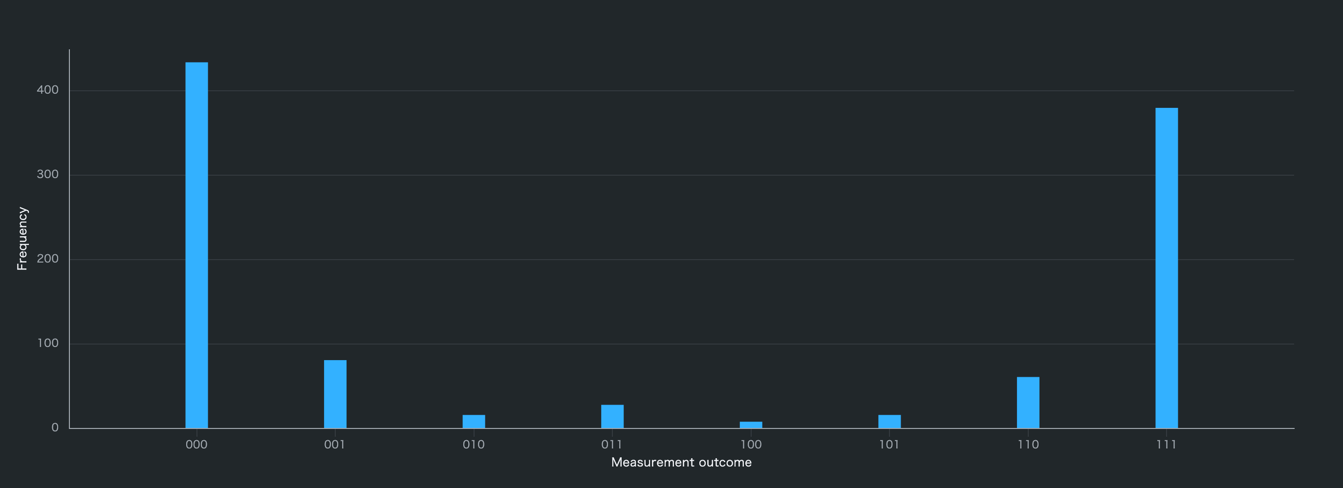
Later, I read a book about "Quantum Supremacy," which introduced me to quantum computers. The idea of fusing my love for quantum mechanics with my passion for making things (hardware DIY) completely hooked me. In my third year of middle school, I used the IBM Quantum Composer to verify quantum algorithms for another project. It was then that I decided I wanted to become a hardware engineer for quantum computers in the future.
![]()
The Hardware Wall: Lack of Access
While I was able to get my hands on the software side of quantum computing, the hardware—which I am far more interested in—was completely out of reach. Aside from facility tours, there was almost zero opportunity to actually touch or interact with it. Since I was a kid, my motto has always been: "If it doesn't exist, build it." So, in middle school, I looked into whether I could build a quantum computer myself. However, I found out it would cost a minimum of 300,000 JPY (around $2,000), which forced me to give up at the time.
Discovering the EFNMR Method
After enrolling in KOSEN, I was determined to take some kind of action regarding quantum computers. I obsessively researched DIY quantum computing again and discovered that by using the Earth's Field Nuclear Magnetic Resonance (EFNMR) method, I could start a project for about 100,000 JPY (around $700).
Knowing this was my chance, I fully committed to building an EFNMR quantum computer. I immediately dove into the details and started by simulating the signals using Python.
EFNMR Quantum Computer Project Details
Operating Principle
- Spin Initialization (Polarization): We run a massive current through a large coil to align the proton spins (in pure water) with the magnetic field, setting the qubit to the |0⟩ state.
- Sequence Switching: Using a MOSFET and a relay unit, we switch the circuit between the high-current coil phase and the highly sensitive signal-reading phase.
- Signal Amplification: When the spins precess and try to return to their original state aligned with the Earth's magnetic field, they emit a microscopic signal (FID signal). The coil captures this, the amplifier circuit boosts it, and it is fed into the PC via a sound card.
- Analysis: The signal acquired in step 3 is processed using FFT and noise reduction in Python to observe the quantum state.
System Configuration
- Microcontroller: M5Stack
- Sensor Coil: 250 meters of 0.5mm enamel wire, painstakingly hand-wound around a PVC pipe.
- Proton Sample: Pure water
- Polarization Circuit: Fully sealed Lead-Acid Battery (to prevent power supply noise), MOSFET, Fuses.
- Amplifier Circuit: Ultra-low distortion/noise Op-Amps (AD797BRZ), Film Capacitors, Fast Recovery Diode.
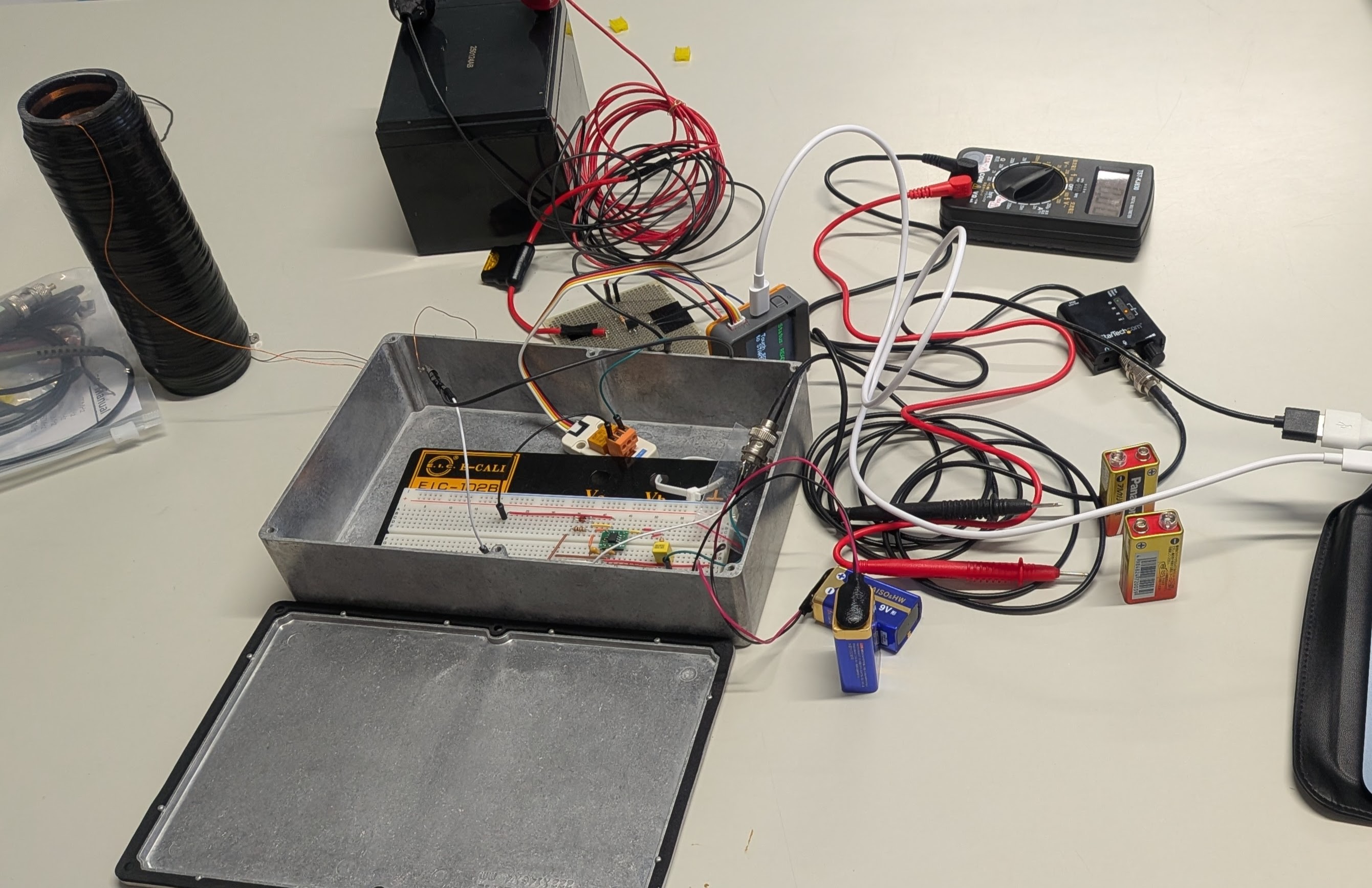
![]()
Development Logs: Past and Future
I have been publishing my past development logs as a "Book" on Zenn (a Japanese tech blogging platform). However, I used AI to help write the text for those past logs because I actually started this project around April 2026, but only began writing articles in September 2026, so I had a lot of catching up to do.
*Note: From now on, I will be writing all project logs manually, without AI generation.*
Currently, we have finished building all the hardware modules and have successfully received the FID signal! However, we are currently struggling with dead-time and severe noise issues, so the signal isn't clean yet. Future logs will cover our battles with noise reduction and circuit optimization.
Democratizing Quantum Computer Hardware
As I mentioned earlier, I have suffered from a severe lack of access to quantum hardware. I believe that in the near future, quantum computers will become just as critical to society as AI is today. If we don't have access to quantum hardware now, we will be left behind. We are already seeing a massive gap between those who understand and utilize AI and those who don't.
Everyone needs to start learning about quantum computers right now, even just a little bit. And there is a huge difference between knowing the theory and actually touching, seeing, and experiencing the hardware. Engineers and students who are interested must have access to both the software and the hardware.
Right now, anyone can try quantum software, but hardware remains locked behind closed doors. Hardware needs an environment where anyone can touch it, just like software!
That is why, through this project, I want to create a pathway for students and engineers who want to tinker with quantum hardware. My ultimate goal is to develop a cheap, easy-to-build DIY quantum computer and open-source the entire design on the internet!
My personal goals for this project are to build this machine, acquire the engineering skills necessary for the future, and share this accessible quantum hardware with the world.
Thank you for reading, and I hope you follow along with our journey!
Trivia: The Origin of the Name "NMRQCP"
"NMRQCP" is both my profile name and the name of this entire project. It stands for Earth's Field Nuclear Magnetic Resonance Quantum Computer Project. "EFNMRQC" was a bit too long, so I dropped the "EF" and added a "P" for Project, resulting in NMRQCP.
EFNMR Quantum Computer Project (NMRQCP)
Democratizing Quantum Computing "If it doesn't exist, we build it. Quantum Computer on your desk."