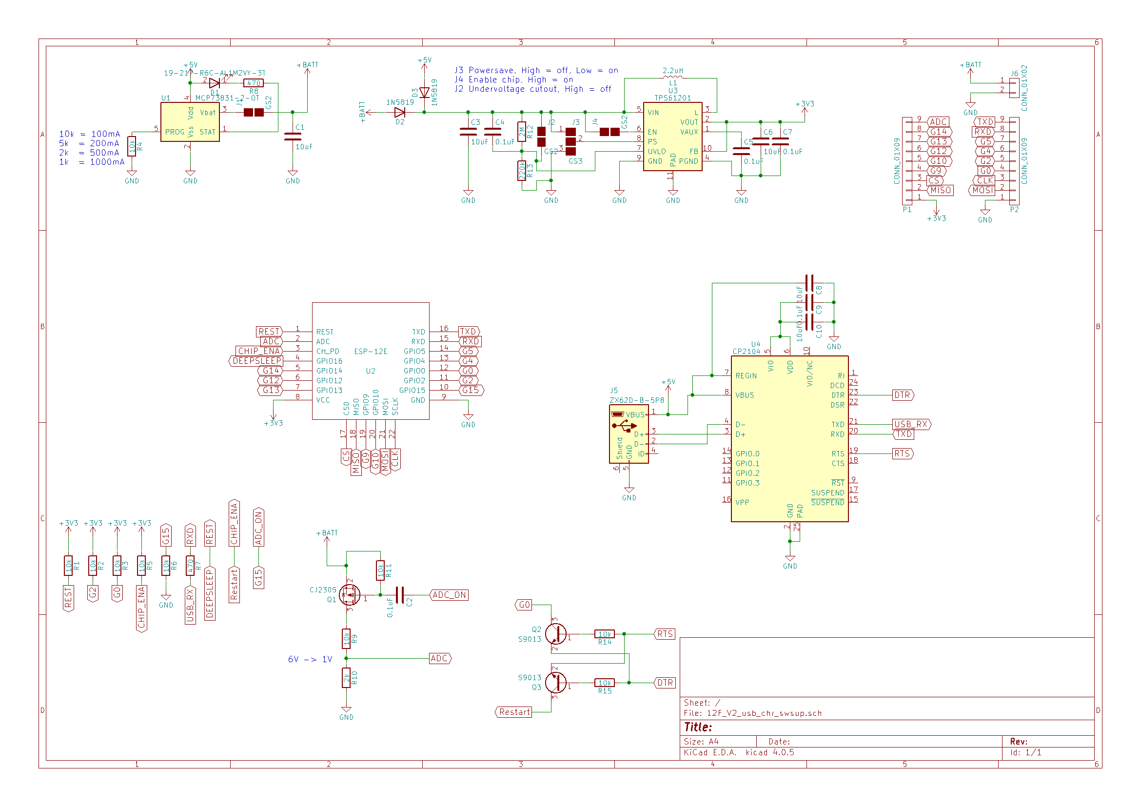
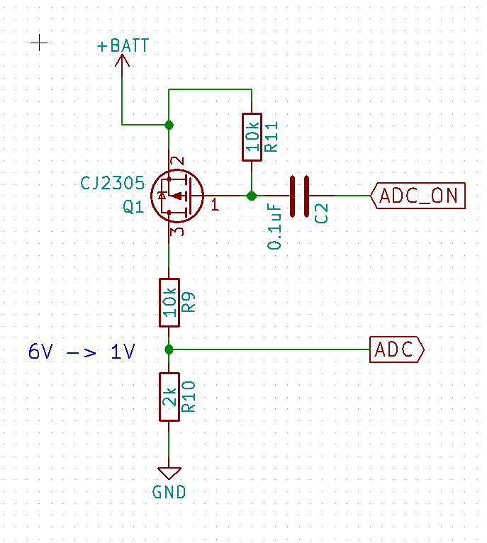
Because the ADC in ESP -12F is only 0-1V I had to make a voltage divider, but voltage dividers drains power constantly. A quickfix could be to chose a high value resistor, but then again the noise could increase or the ADC might be affected by the high impedance. So I wanted something better. With some google magic I found that others had used a transistor to turn on and off the voltage divider.
The reason that the transistor is on the high side of the divider is because otherwise the ADC input will be exposed to the battery voltage when the transistor is "open"(high impedance).
Using a high side transistor(PMOS) introduce another problem. To be able to put it in "open" state, the gate(1) - source(2) voltage needs to be <=0V. A 3.3V µcontroller can't put out say 4.2V like in a fully charged LiPo battery. One way could be to but transistor in between to step up the voltage, but I found one way that works really good in this case and it is cheaper by using a capacitor instead as the step-up stage.
It works in the way that the capacitor is conducting the AC part of the signal on ADC_ON. So falling and rising edge on a pulse will "jump over" the capacitor and "open/close" the transistor. According to some forum post a falling edge will "close" the transistor for 2 ms, enough time to make one sample of the voltage on the ADC pin.
Here is some example code I have used with success:
digitalWrite(15, LOW); //Close transistor
int sensorValue = analogRead(A0); //Measure
digitalWrite(15, HIGH); //Open transistor
// Convert the analog reading (which goes from 0 - 1023) to a voltage (0 - 5V):float voltage = sensorValue * (6.85 / 1023.0);
ADC_ON is connected to pin 15 on the ESP.
I tried with delay(1) between LOW and READ but that was to long. This code have worked without problems.
The 6.85 value is the value that corresponds to the battery value when the ESP measures 1V, but this was tested on one of my units and your miles my vary.
Tip: connect to a good power supply and check what this code read and the calibrate the 6.85 value to something that works good for you.
Long time, no update... But I have slowly made some progress. I finished the design before the summer but then let it rest for a bit. Then after the summer I started to look into ordering PCBs and components. QFN and 0402 are not funny to solder by hand.
So I looked more and more into PCBA services.
Found some different companies, but most of them required a lot of work or money to produce my boards. Then I found https://www.elecrow.com/cooperated-designers/ and sent them the gerber and BOM files. They where very helpful in the process of deciding amounts, finding components and other stuffs. After some emails and payment they produced 50 units. 25 for me and 25 for their online shop so everyone here can buy one if they want: https://www.elecrow.com/homefixer-esp8266-devboard.html.
Now I got 25 to test together with a friend and will update more when there is smoke ;) and testing.
Requirements: 6V -> 1V, don't destroy the input, low power
Fixed divider
N-FET
P-FET with capacitor control
P-FET with N-FET control
1 is out because it requires continues current and really big values on resistors.
2 might put 6V on the ADC input when off, we don't want that.
I thought of 4 until I found 3. 3 will be cheaper and smaller to implement and I hope it will work so I'm going for that at the moment. Values of resistor will be decided later to keep number of rows in BOM as small as possible.
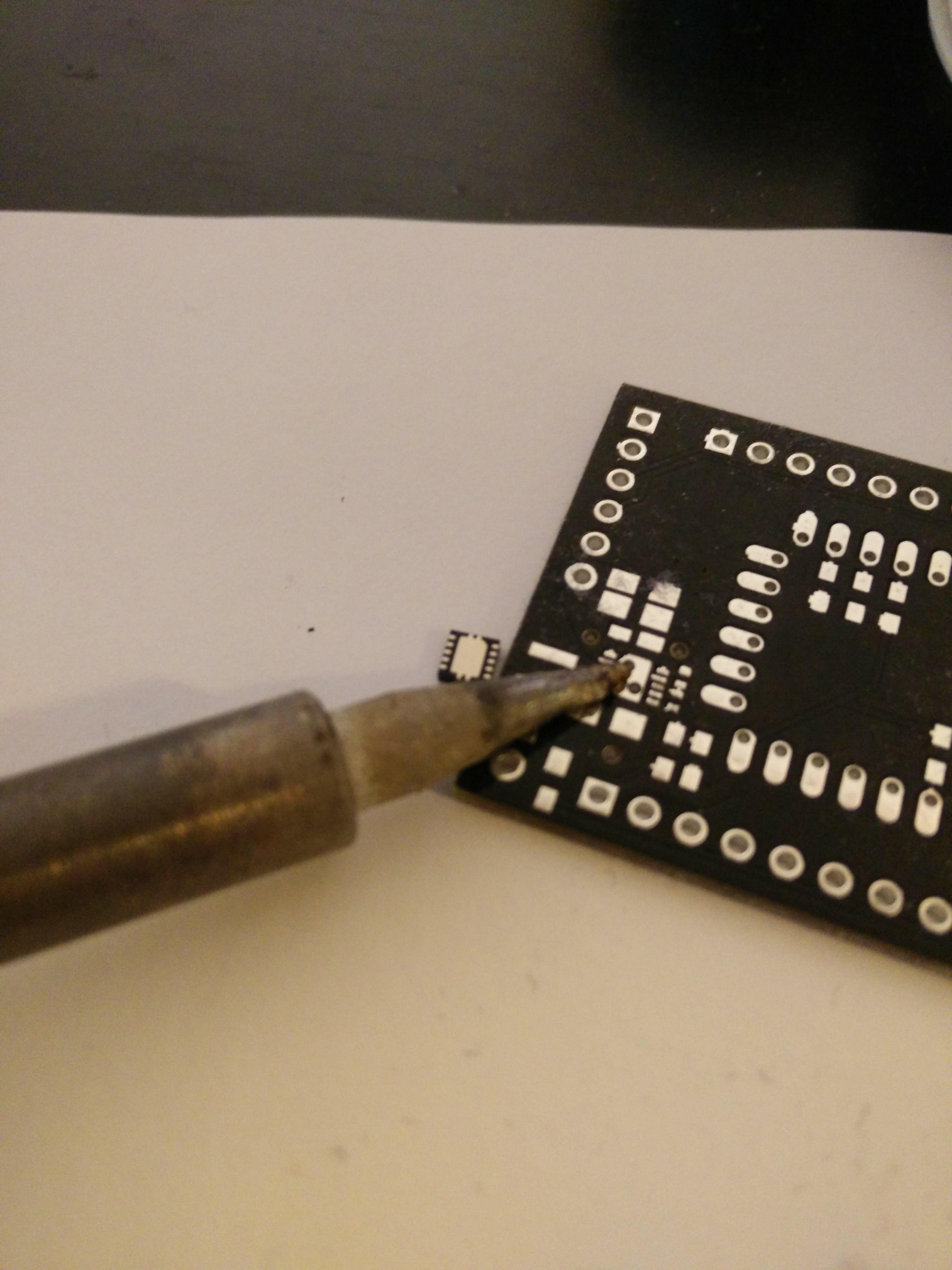
As got all components one week ago, I started to solder 5 boards. Result: 2 out of 5 works.
First problem was the tools I had available and the size of the components. To solve it I put on a lot of solder and then removed it again just to get flux on the pads. It really helped in sucking the solder to the pads and component the next time.
I believe that there is some shorts under the QFN on the bad ones. Will look more into it later, but for now the priority is to make 2.0 with fixes and features I really miss in 1.0.
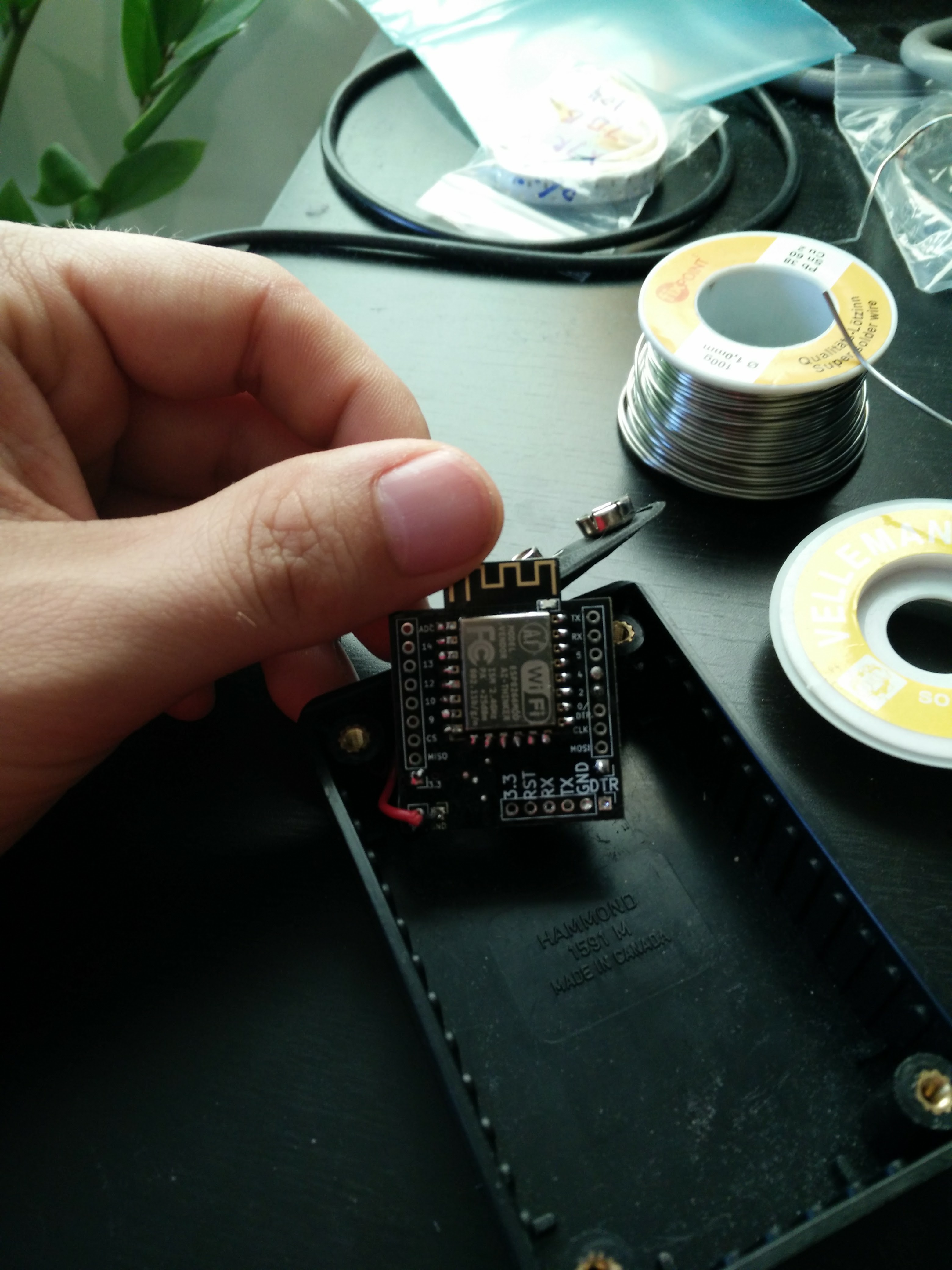
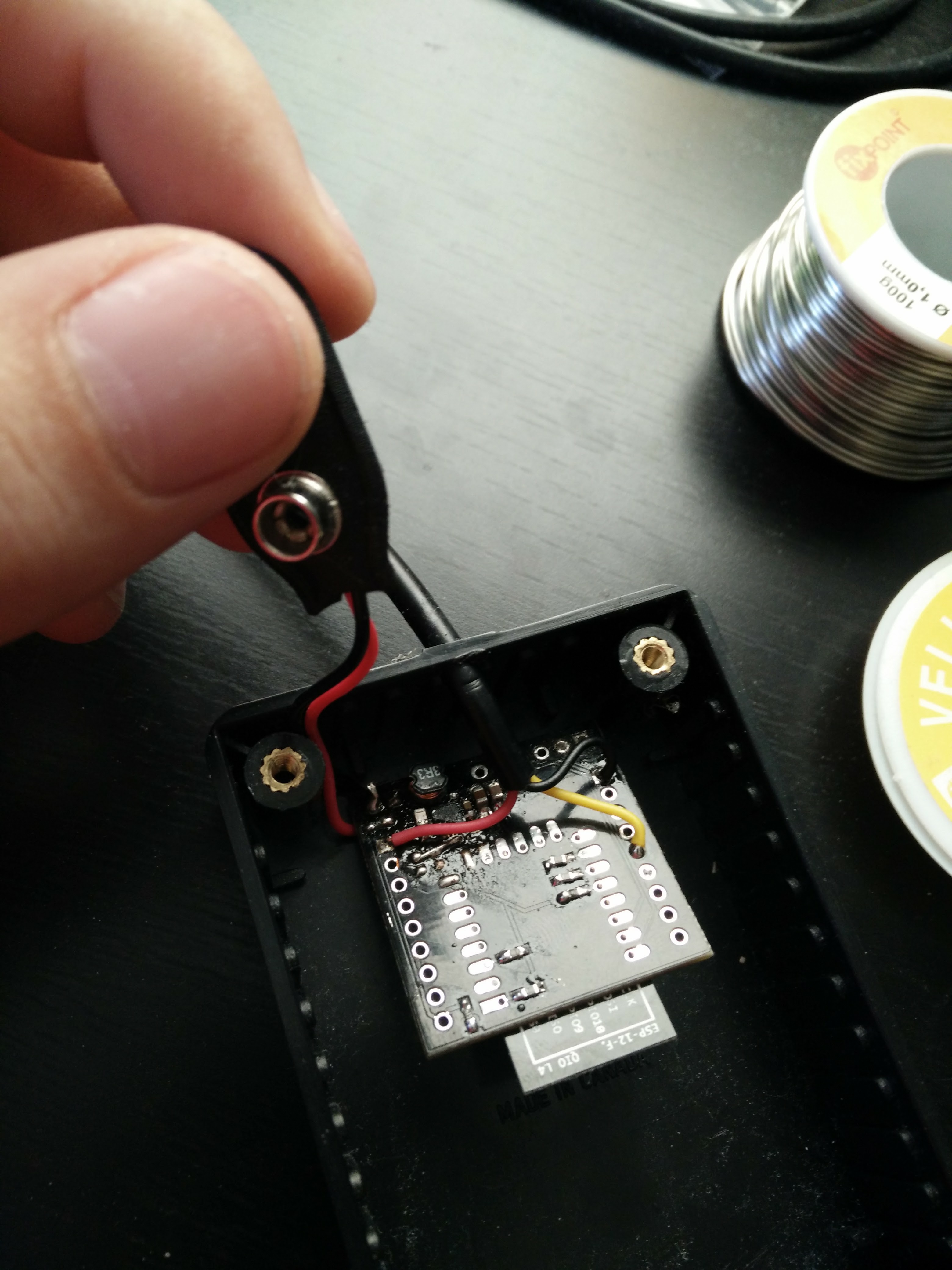
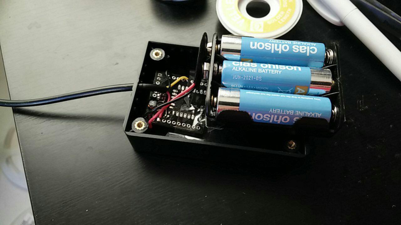
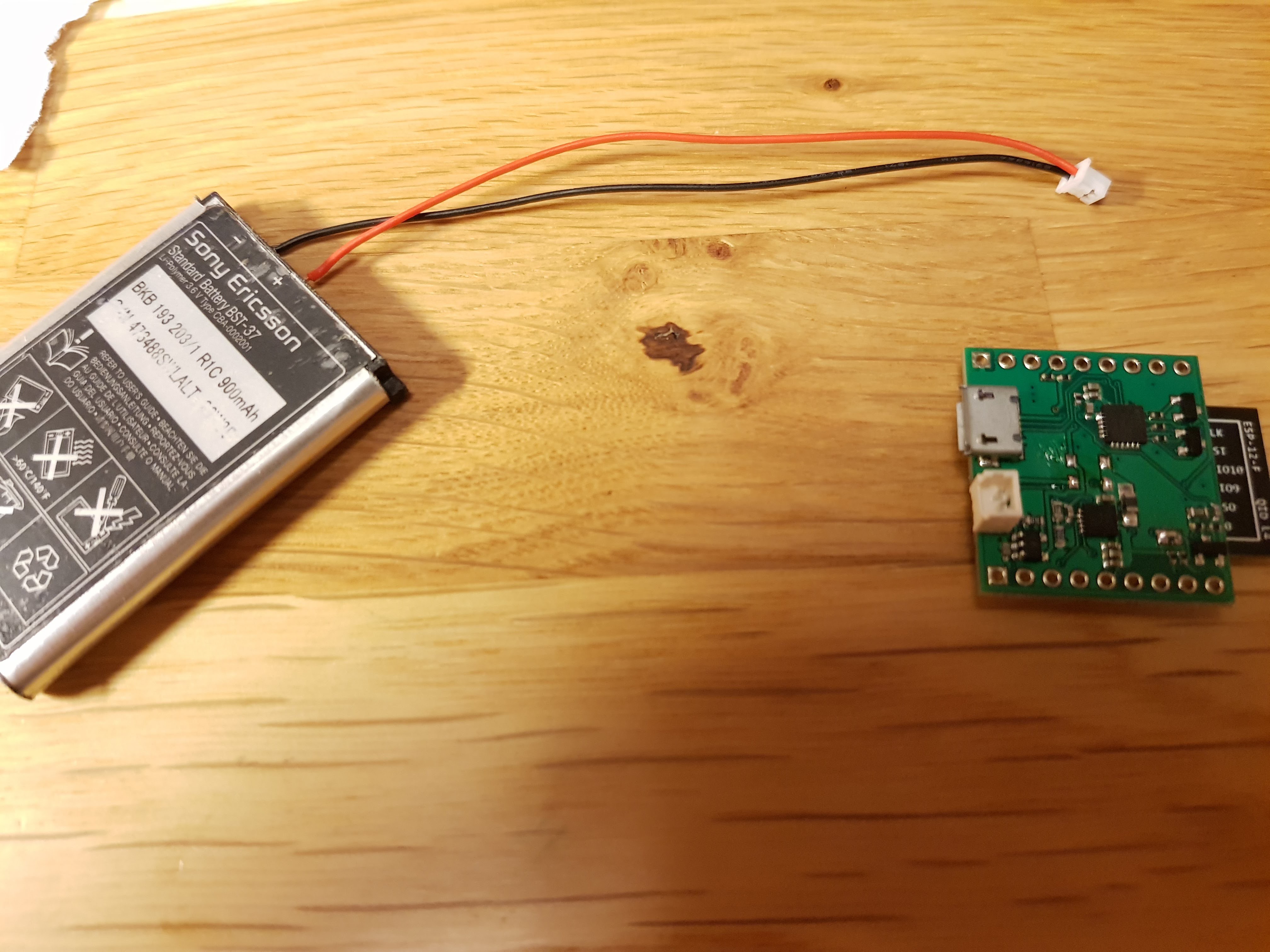
One of the boards was put into use as a wifi thermometer sending data to thingspeak every 10 minutes. It have been running for a week with only missing half a day because the ADSL modem went down. The box haven't been touched after it was closed.
Some more problems discovered:
ESP8266 only reads 0-1V on the ADC, will have to edit the current design.
PCB was .1" to big for my breadboard, have to squeeze it a bit for the next one.
The current placement of the temp. sensor makes it a sun detector. xD
TIP: If using seeedstudio that have 100x100mm boards *10 for 9.9 USD. If your board is rectangular and smaller then 100x100mm, PANELIZE it :) I put 9 copies on the 100x100mm board and in that way got 90 boards now :D see the background picture for the result.

 With some google magic I found that others had used a transistor to turn on and off the voltage divider.
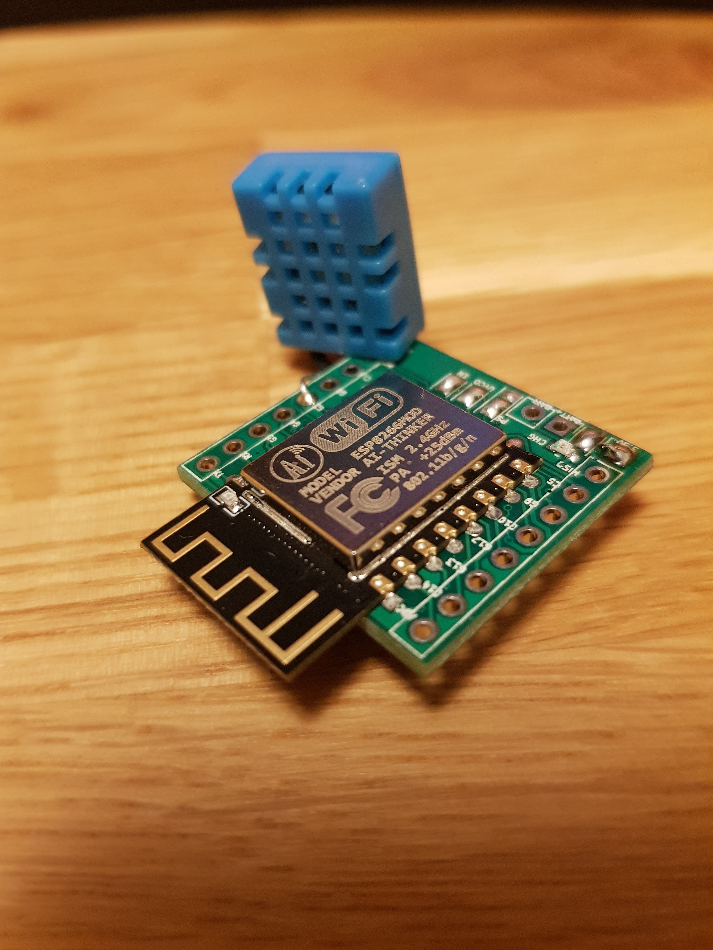
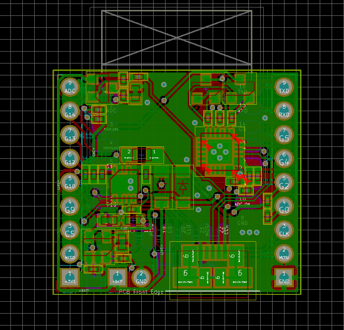 Now V2 is almost done, some small DRC errors to fix before I can order it.