 Vítor Barbosa
-
1Step 1
Add STM32 support to the Arduino IDE
Thanks to the guys from http://www.stm32duino.com/ we are able to program the STM32 family using Arduino. What you need to do is very simple:
- Install Arduino SAMD Boards package with the Arduino Boards Manager
- Download or clone the Arduino_STM32 into the Arduino/hardware folder
- Open the IDE, select your board (Generic STM32F103C series if it's the blue or red pill) and Serial as Upload Method to program using the USB-Serial adapter (like FT232R)
Connect the board by following my little sketch. You may test it with the ordinay Blink code, just note that the onboard led is on PC13 and that you will need to change the position of the first jumper to switch between Run and Program modes.
![]()
-
2Step 2
Display and power source
Once we've made sure the main board is working, let's add the touch screen. The wiring is described in my drawing and also in the sketch code.
![]()
Some pictures of my version:
![]()
![]()
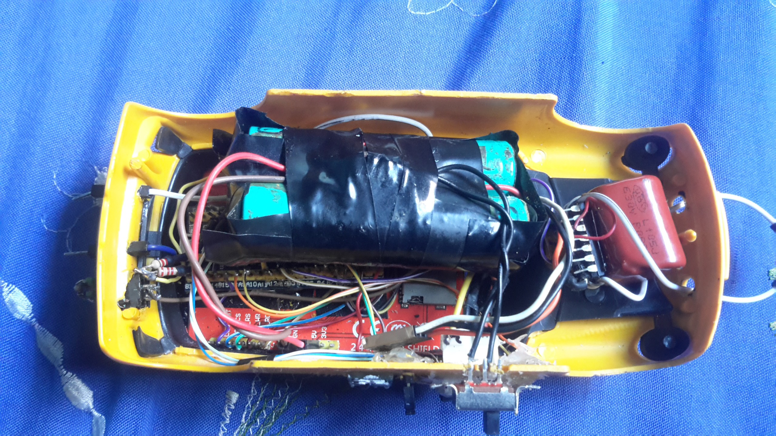
I've put the regulator(7805), battery(7.2V li-ion) and switch together. The jumper cables connect to the display 5V and GND pins directlty.
![]()
![]()
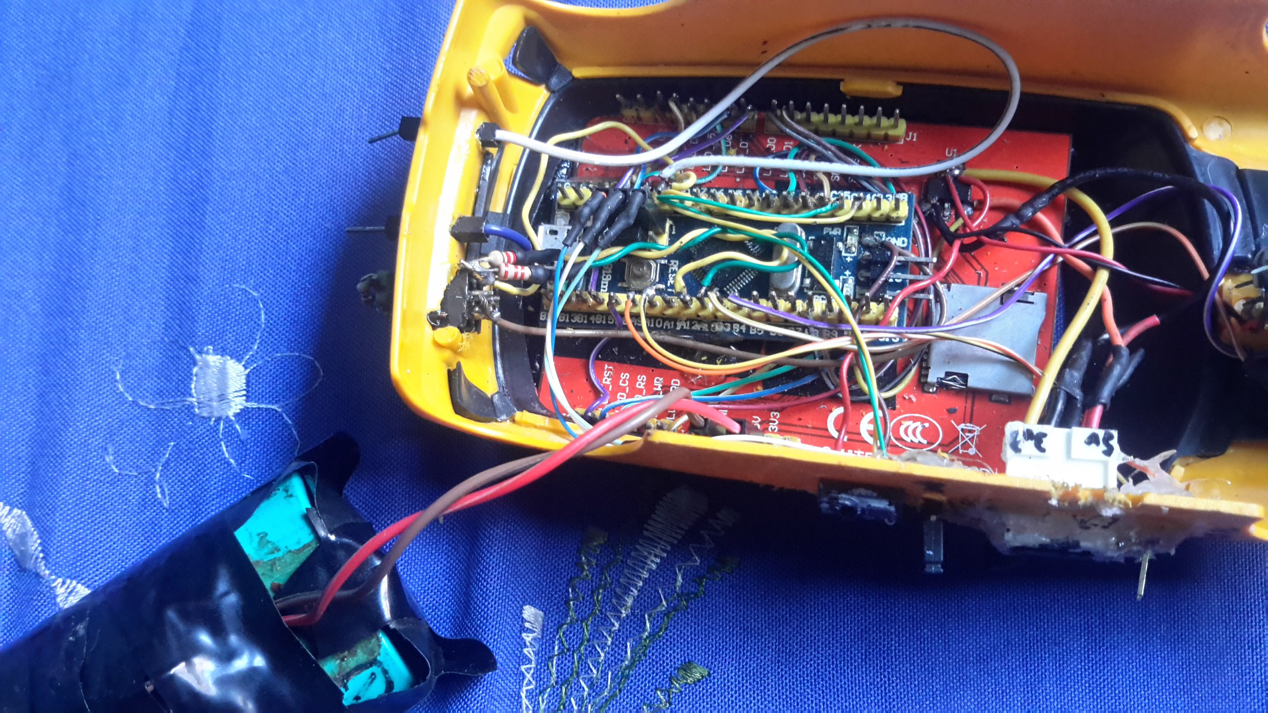
This is the full scope, so just pay attention to the blue pill and display.I know... it's really messy. That's why we have a nice cover to hide everything!
![]()
-
3Step 3
Test the display
Before proceeding, you should test the display and touch to see if everything is working.
The patched TFT library contains code that might not work well with the default Wire library due to pin conflict, so let's edit a few lines to avoid trouble:
- Go to Arduino\hardware\Arduino_STM32\STM32F1\libraries\Wire
- Open Wire.h with a text editor you like and look for #define SDA
- Make it like this:
#define SDA PC15 #define SCL PC14- Save the file. Now SDA is on PC15 and SCL is on PC14.
I've modified the original example a little, and so may you to adjust the touch sensitivity constants. Upload it (the file is lcd_touch_paint.ino) and you should get something like this (the picture is Adafruit's):
![]()
-
4Step 4
Signal in, signal out
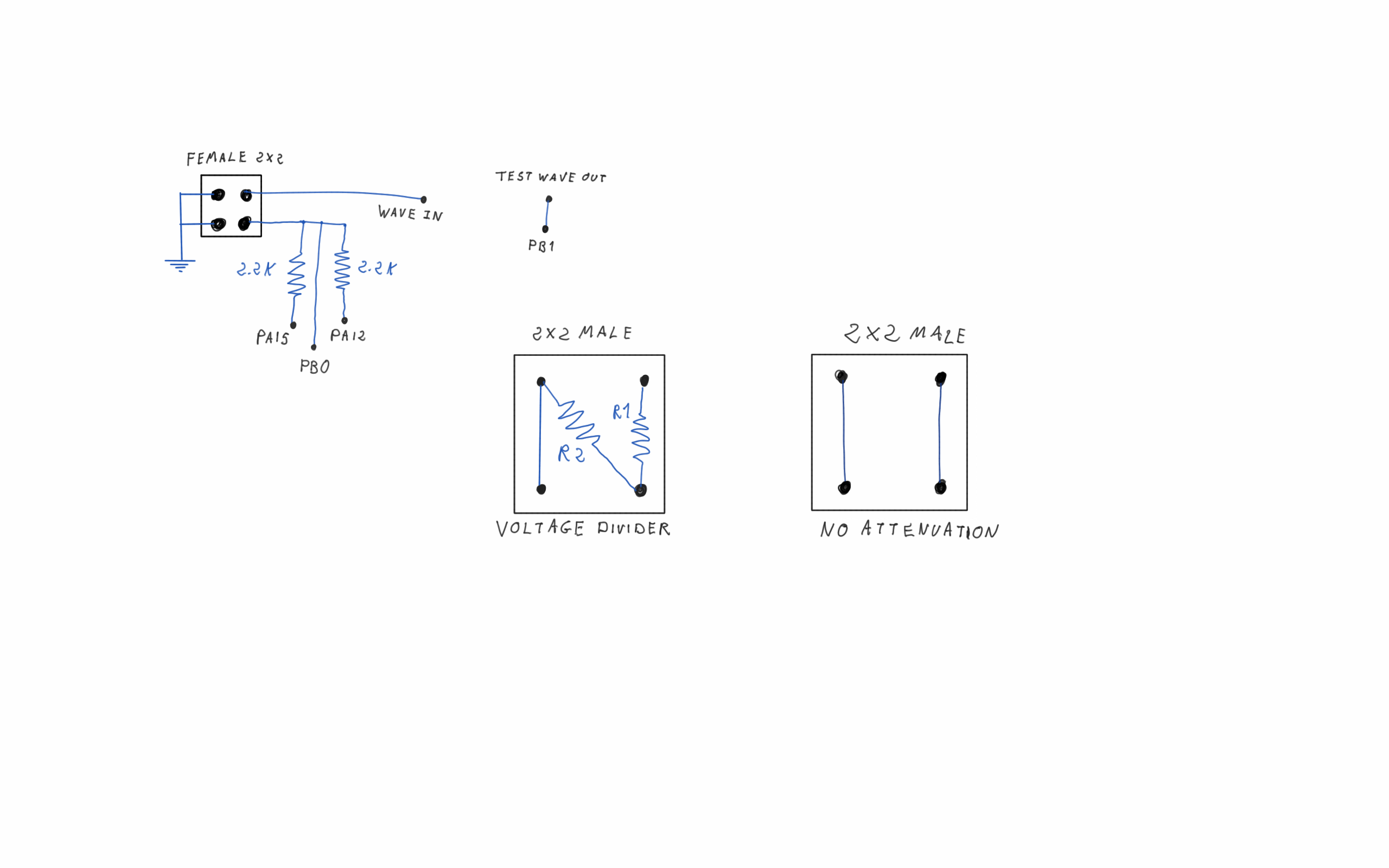
Now, follow the diagrams to build the signal input and attenuators as well as the test wave output pin.
![]()
The same wave input pin is connected to 3 of the STM32 pins, what allows us to very easily monitor when the signal is rising or falling through pin interrupts, thus getting information on pulse width and frequency.
You may build the voltage divider that suits you best according to the formula below, remembering that Vout must never exceed 3.3V.
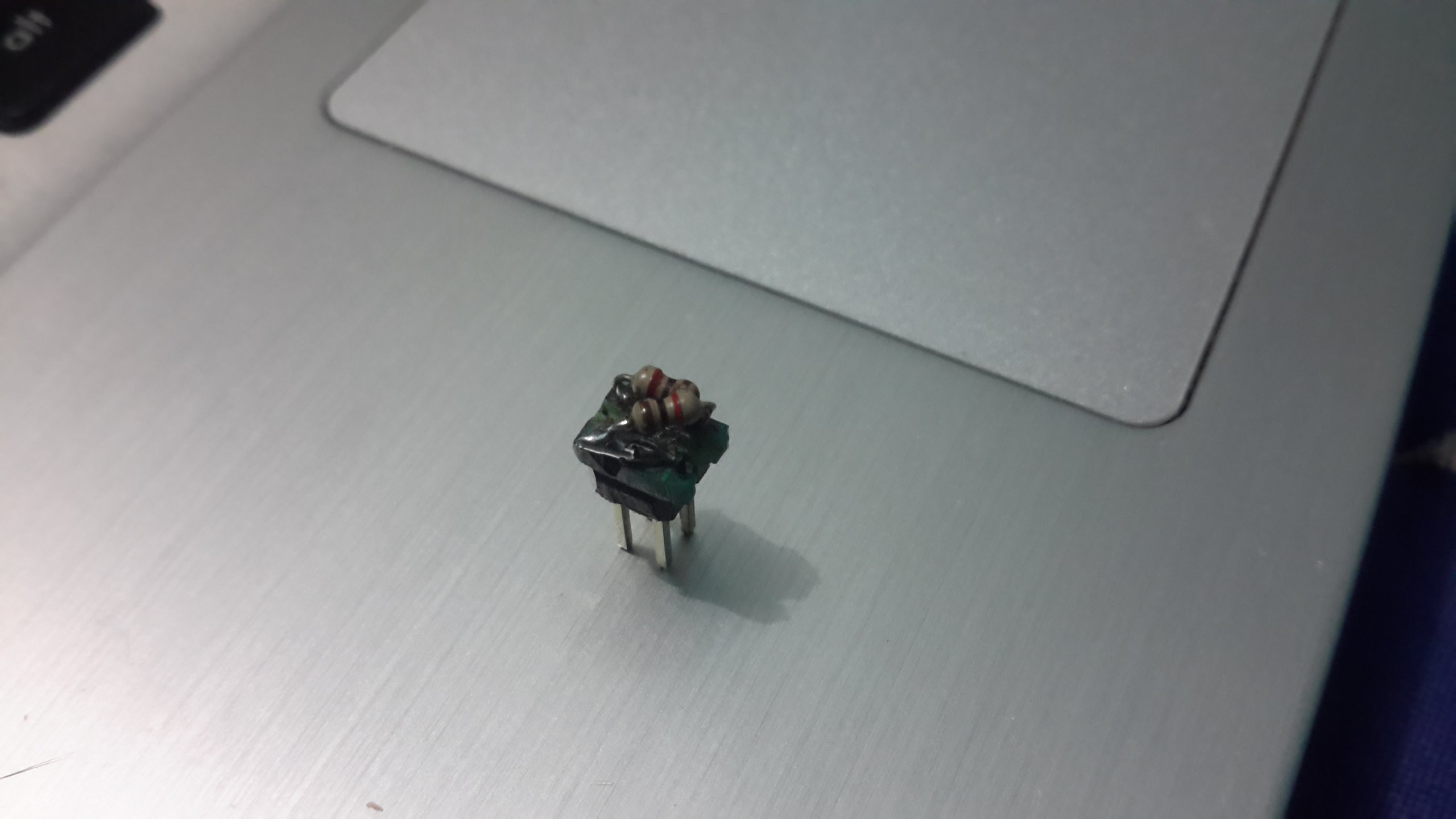
My standard divider for 6V was built using two 1k resistors:
![]()
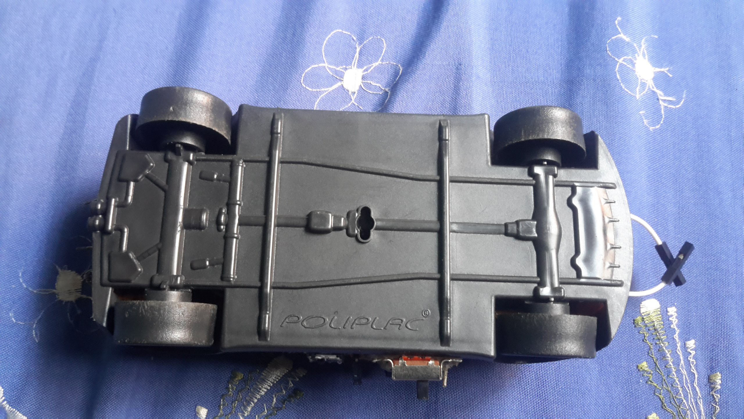
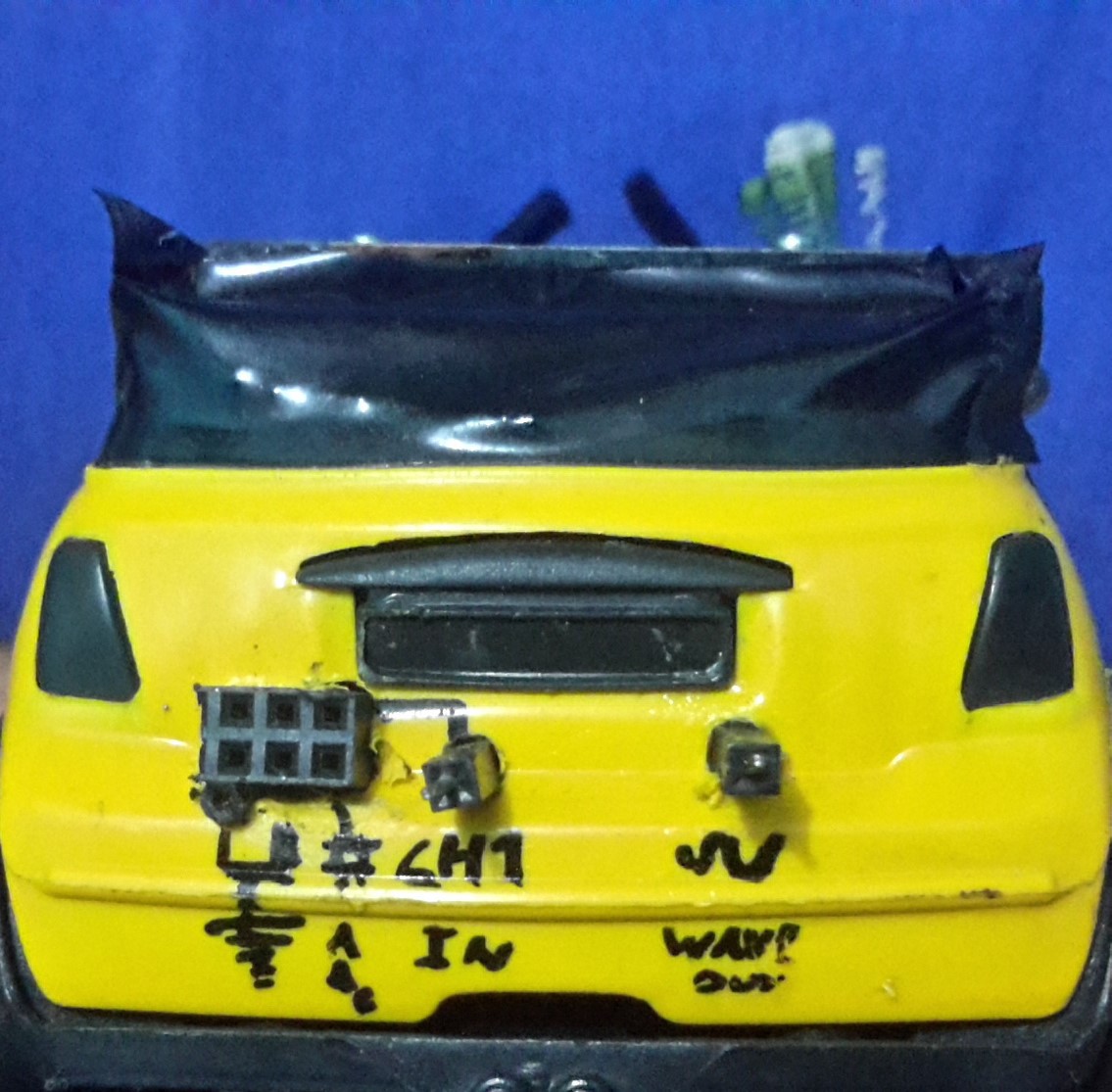
And here is the scope/sports car back:
![]()
-
5Step 5
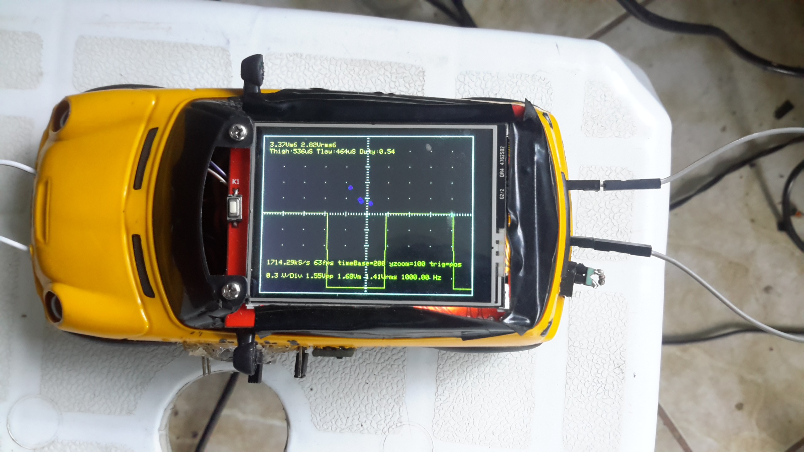
Testing the scope
At this point, the scope is already capable to do most of its job. You just have to upload the multiScope sketch.
![]()
A small note on the blue dots: they're there just to highlight the screen points that have been touched by the user. I kinda liked it, but in case you didn't, just edit the code to disable them.
-
6Step 6
Tuning up our car: the inductance meter
To make it even more useful, you might add an inductance meter. I did so because I had a multimeter that could measure capacitance, but would give me no clue about the value of an inductor.
I've found the current implementation to be good for values above 90uH, while maintaining about 10% precision, so there's still a lot to improve.
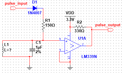
![]()
Connect pulse_input to STM32's PB3 and pulse_output to PB4. The circuit receives an input pulse that makes the LC tank resonate. LM393 is there to turn the sine wave into a square wave, which is then fed back into the MCU. For more info about this circuit, see this site
-
7Step 7
That's it!
Feel free to build upon the existing code and use the remaining pins of STM32 to include any other tool you need.
multiScope
Fast, Portable and Affordable Oscilloscope and Inductance Meter

Discussions
Become a Hackaday.io Member
Create an account to leave a comment. Already have an account? Log In.
I just had to say, that I love your "Mini" scope. B-)
Do you think it would work with a Dodge Charger too?
Are you sure? yes | no
Sure, and I bet you might even get a higher sampling rate ;)
Are you sure? yes | no