Morning.Star
-
Installation
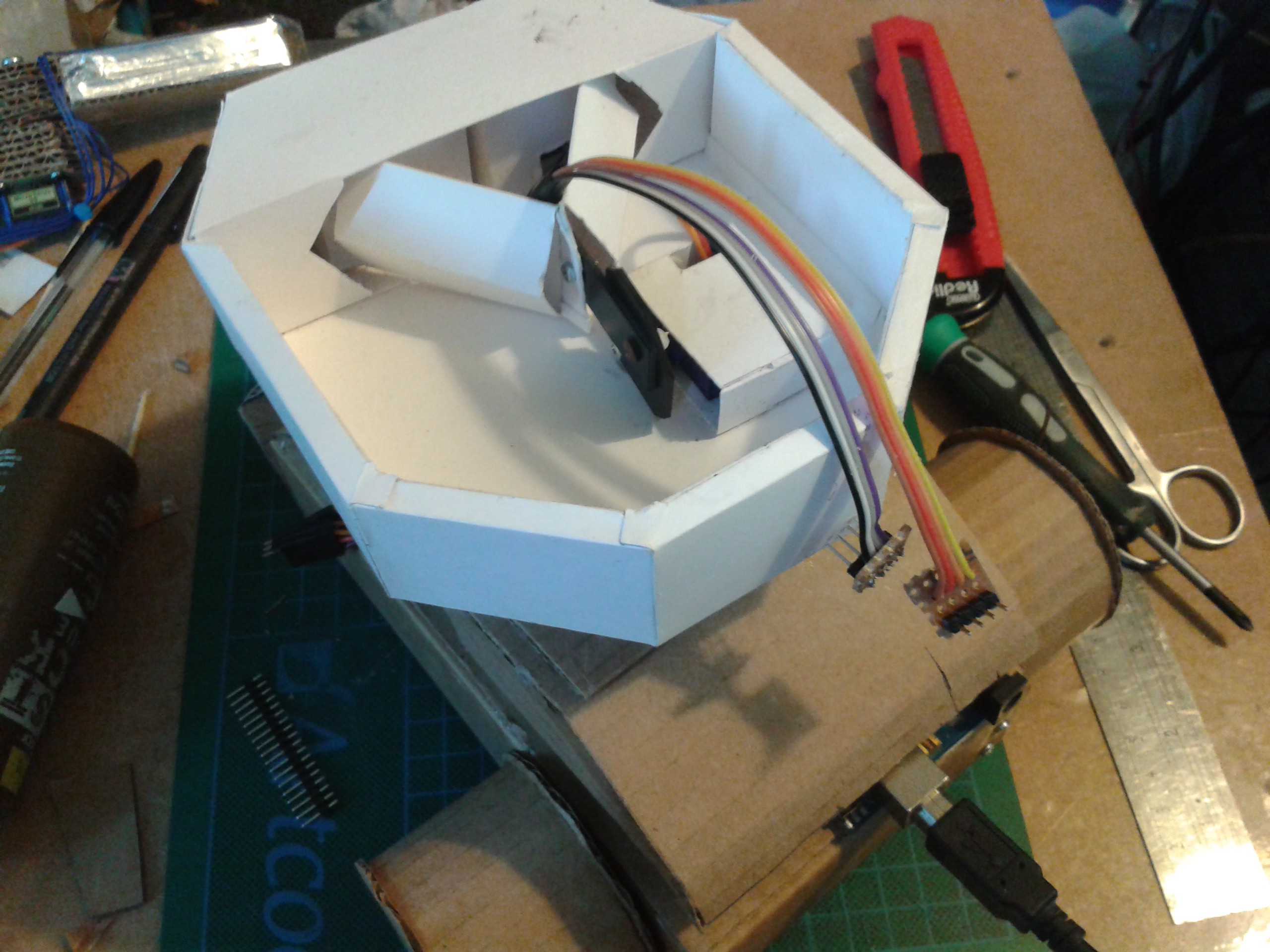
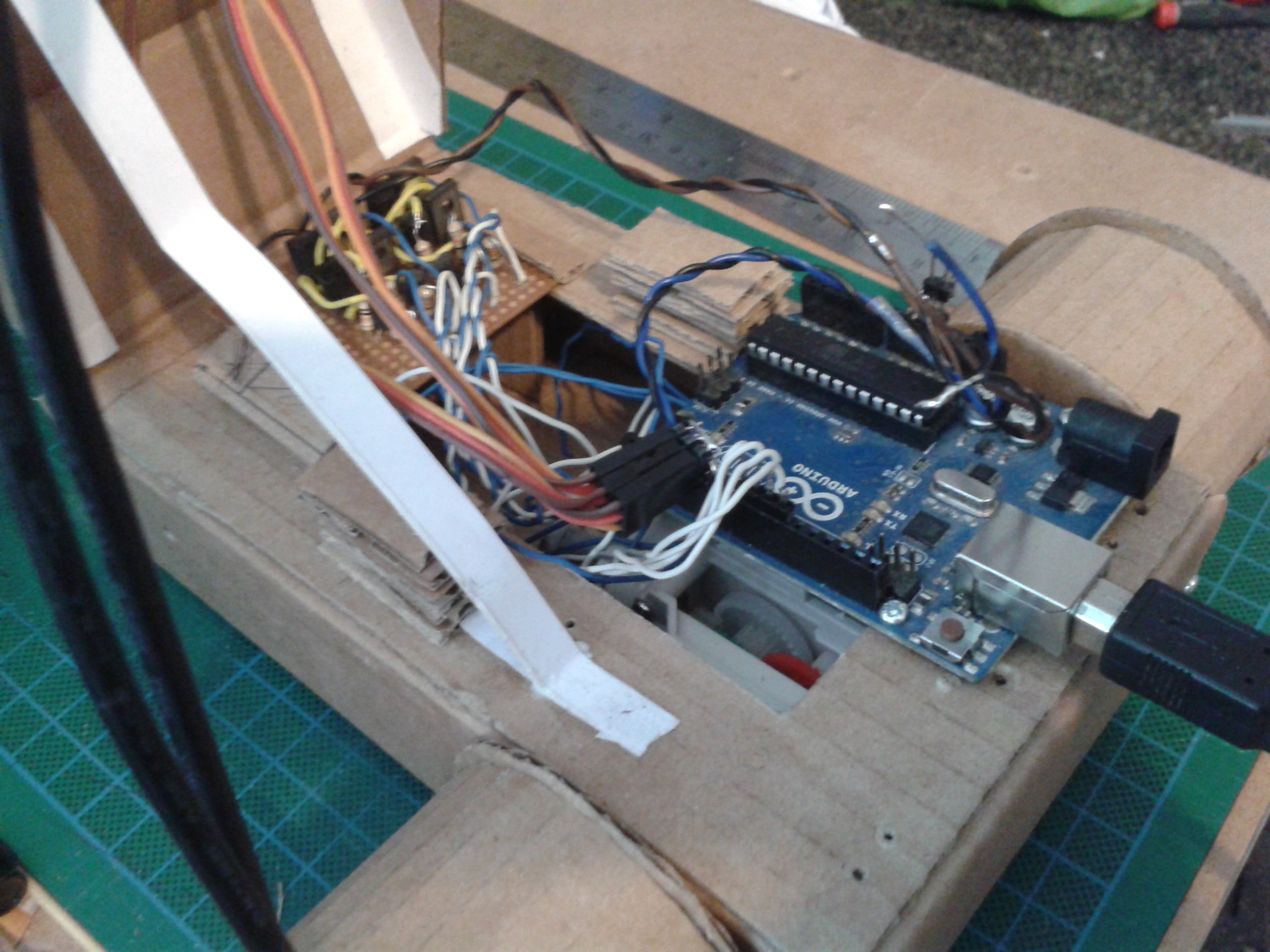
05/06/2017 at 11:10 • 0 commentsNow all the infrastructure is built, I can start putting the systems together. First thing is run all the power and signal cables a bit more neatly so they dont interfere with the mechanisms.

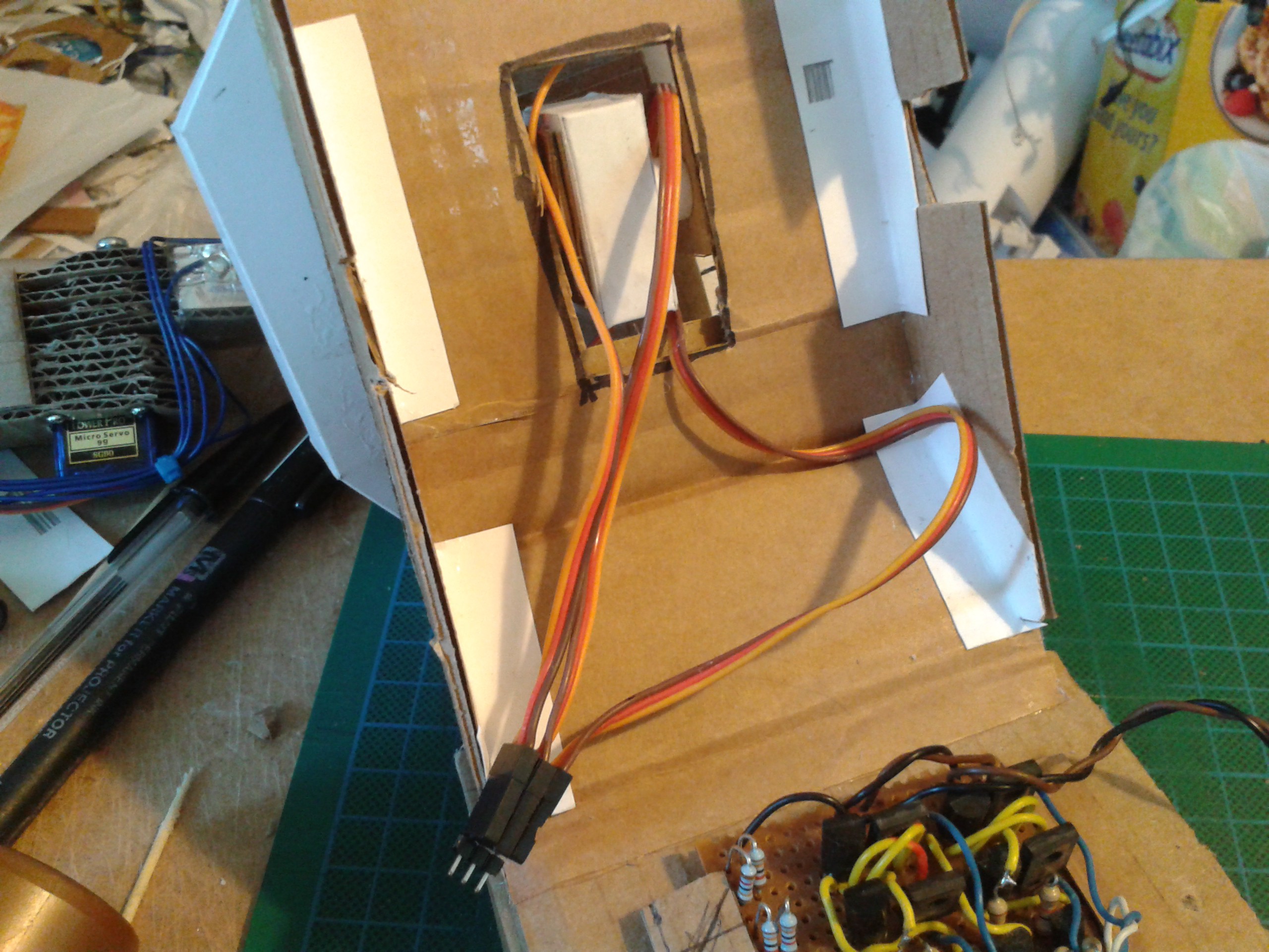
Plenty of room to bring cables down through the neck joint.
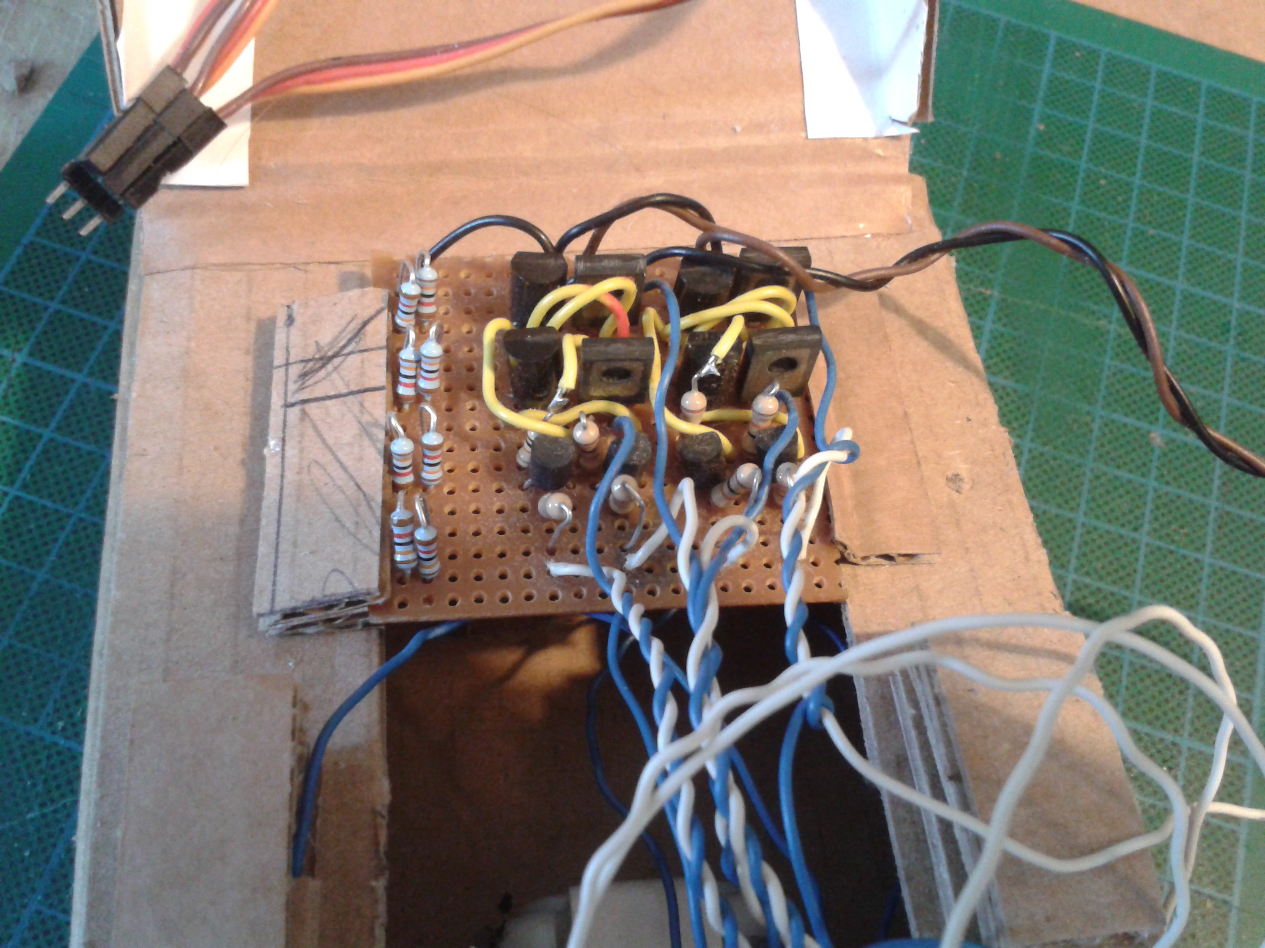
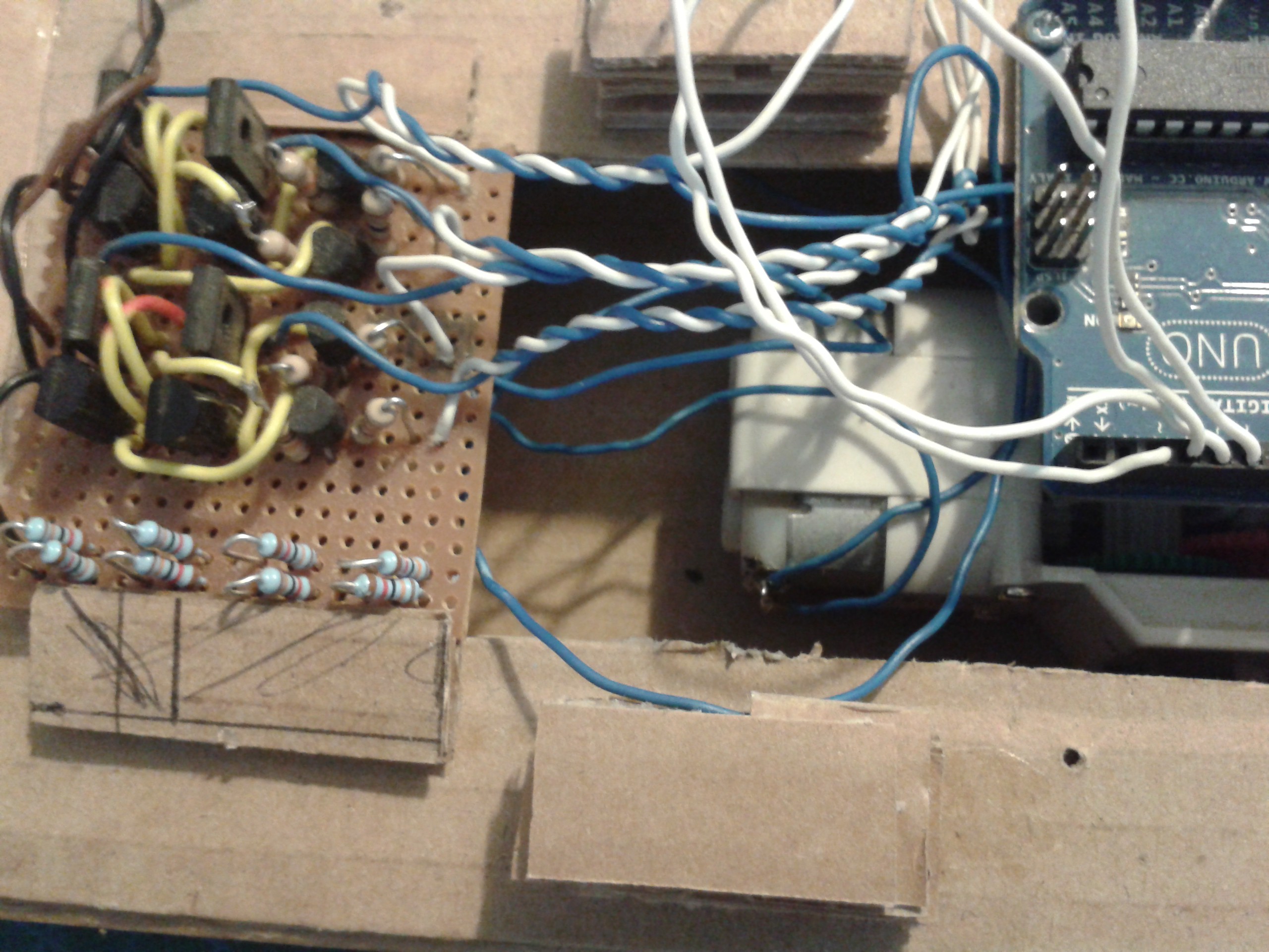
Thats a pair of H-Bridges I built ages ago to experiment with. The resistors on the left are a voltage divider for a series of bump-switches, they arent being used.
Both the motors are wired into the bridges for testing.
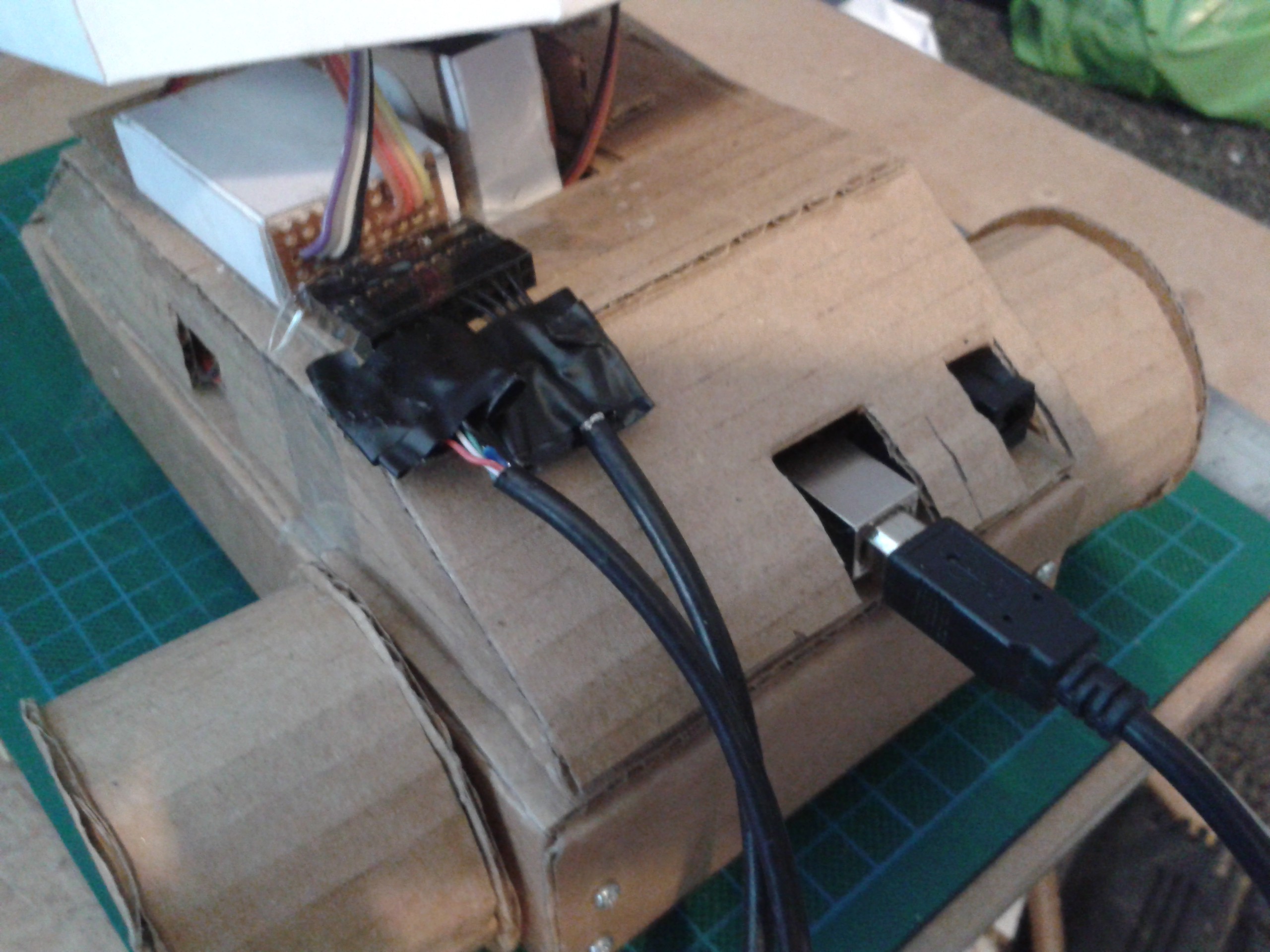
Add the neck and eye servos, tidy up all the wiring - make sure that all the grounds are commoned and add a strap for the lid. All it needs now is a host computer and a power supply for the motors and its ready to roll.
Wire in the cameras and its ready for testing - once I find some decent axles. I'll have to glue these into the track hubs and put a circlip on each to stop them from coming back out again as I really dont want to use those kebab sticks...
-
Skunkworks
05/05/2017 at 14:28 • 0 commentsYeah I know, I've been howling a little about lack of funds and therefore lack of hardware. Good news, I have some servos on the way! Another 8 x 9MGS, none of the plastic rubbish that caused me most of the grief.
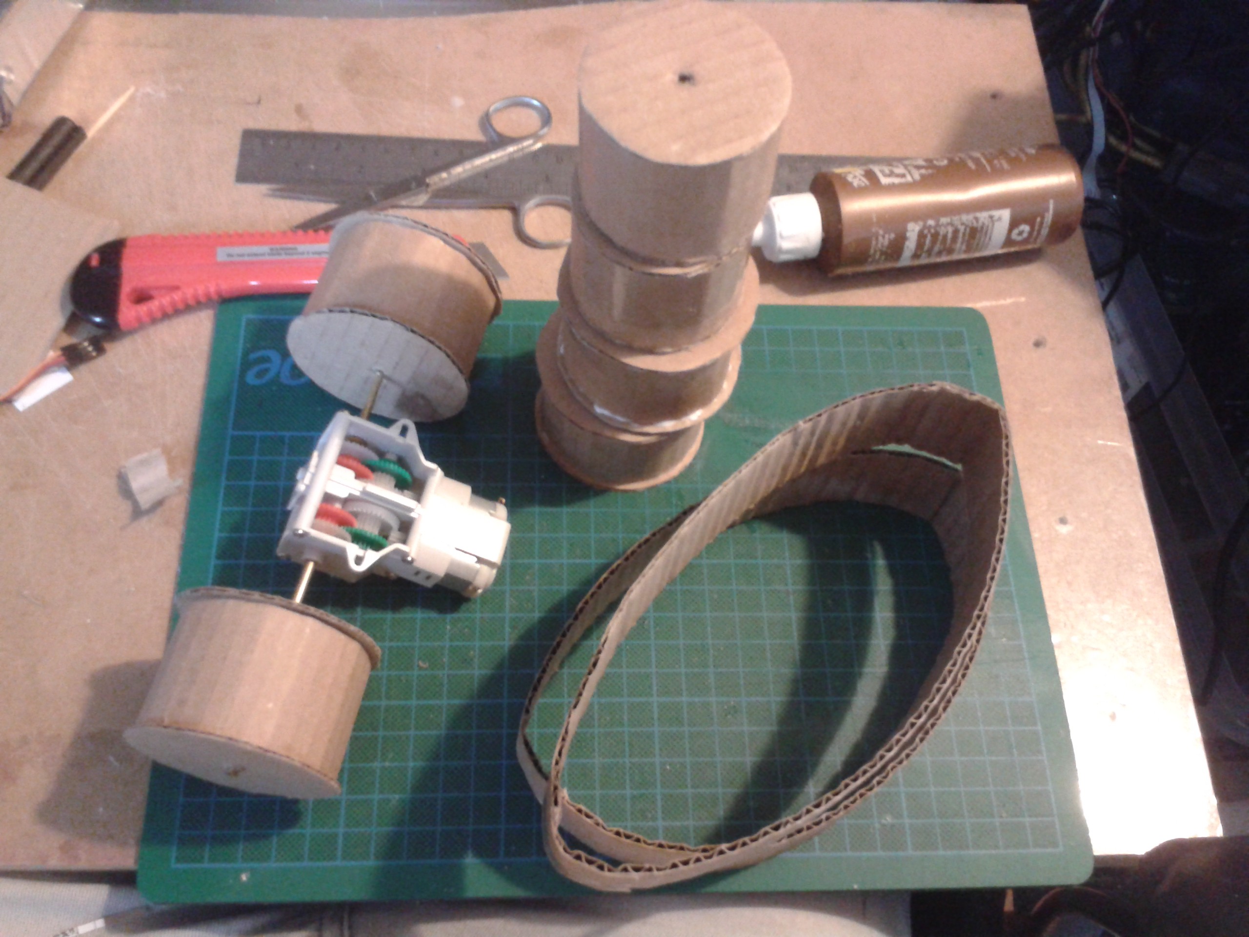
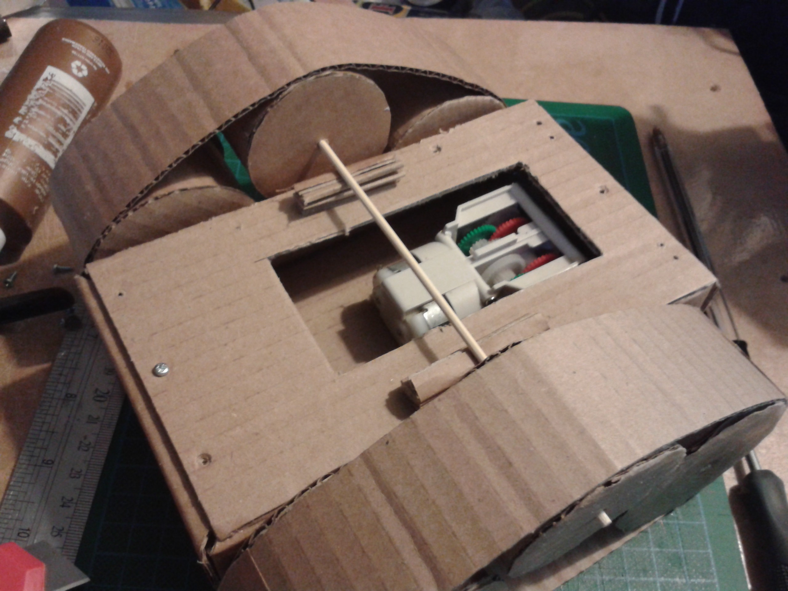
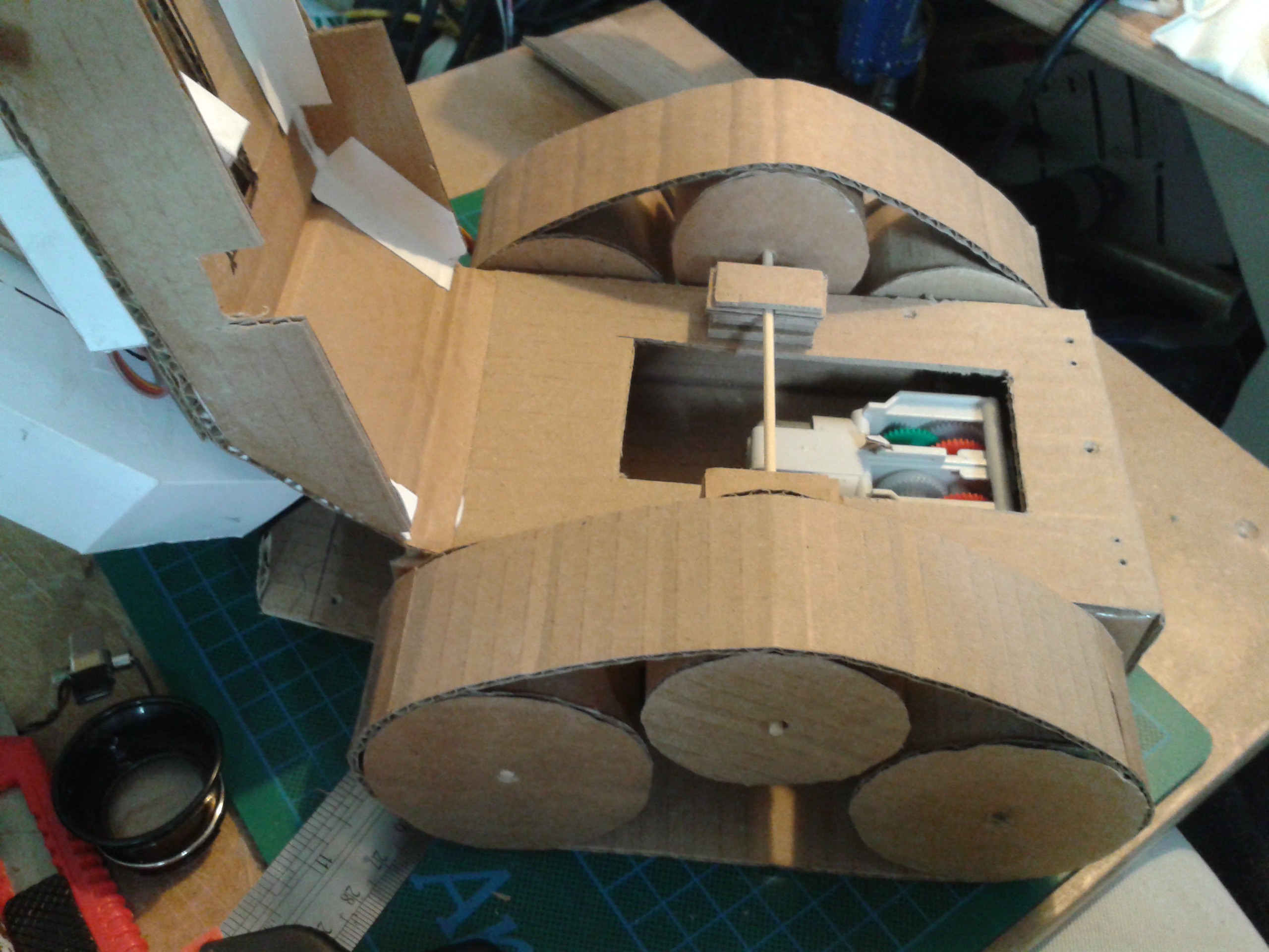
In the meantime, I still need a mobile platform to test the 3D vision system with. I've been looking at a tracked base because I have all the components laying around :
A pair of 1:70 gearboxes and 5v DC motors. This one is a piece of a kit but this mechanism could easily have been chopped out of a toy. It doesnt have any way of detecting the position. More on that later...
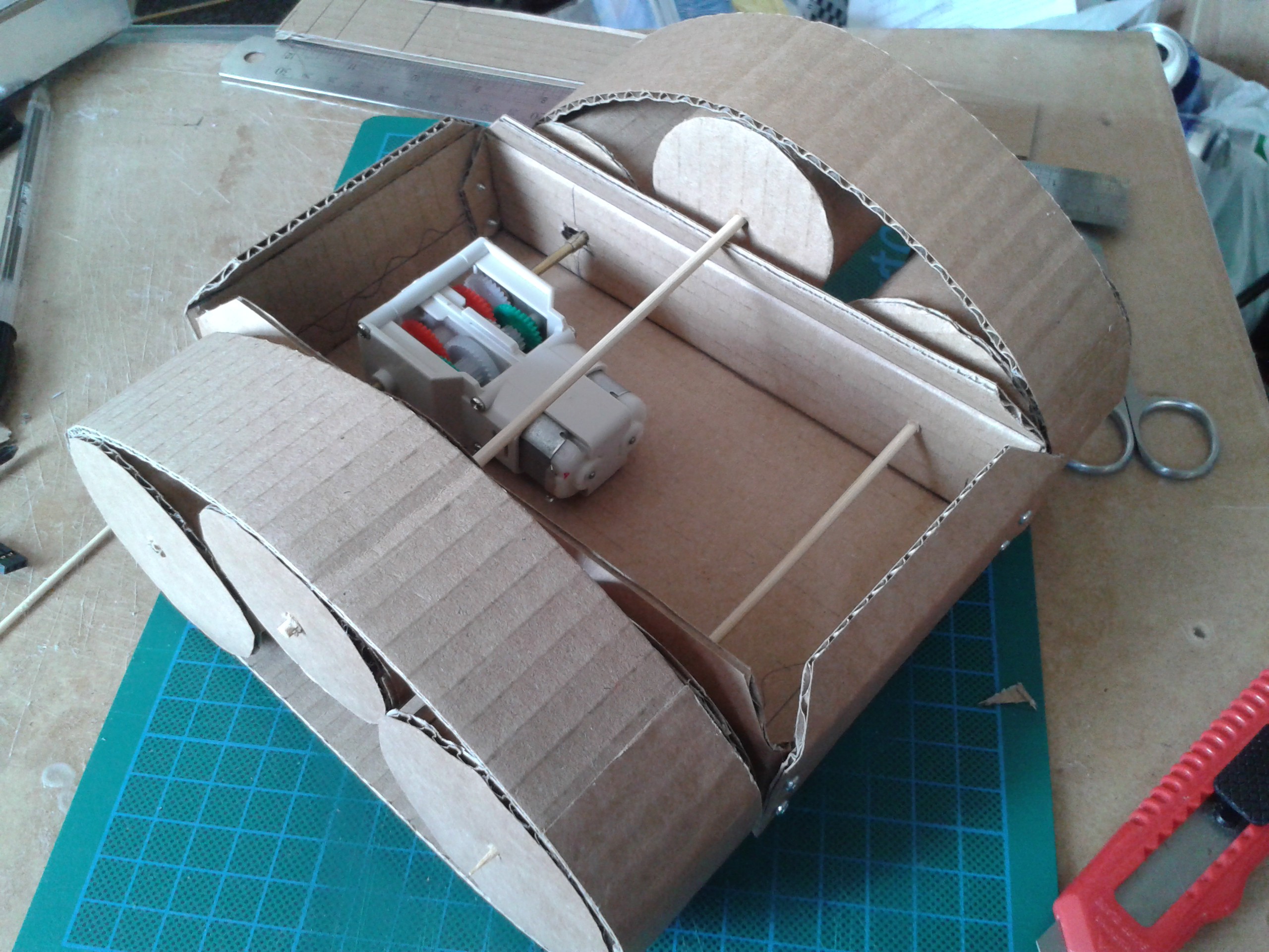
There is something raw about grabbing materials and a rule and prototyping out of your head. It leaves CAD completely cold.
Those kebab skewers are temporary, I'm trying to find something a little more substantial...
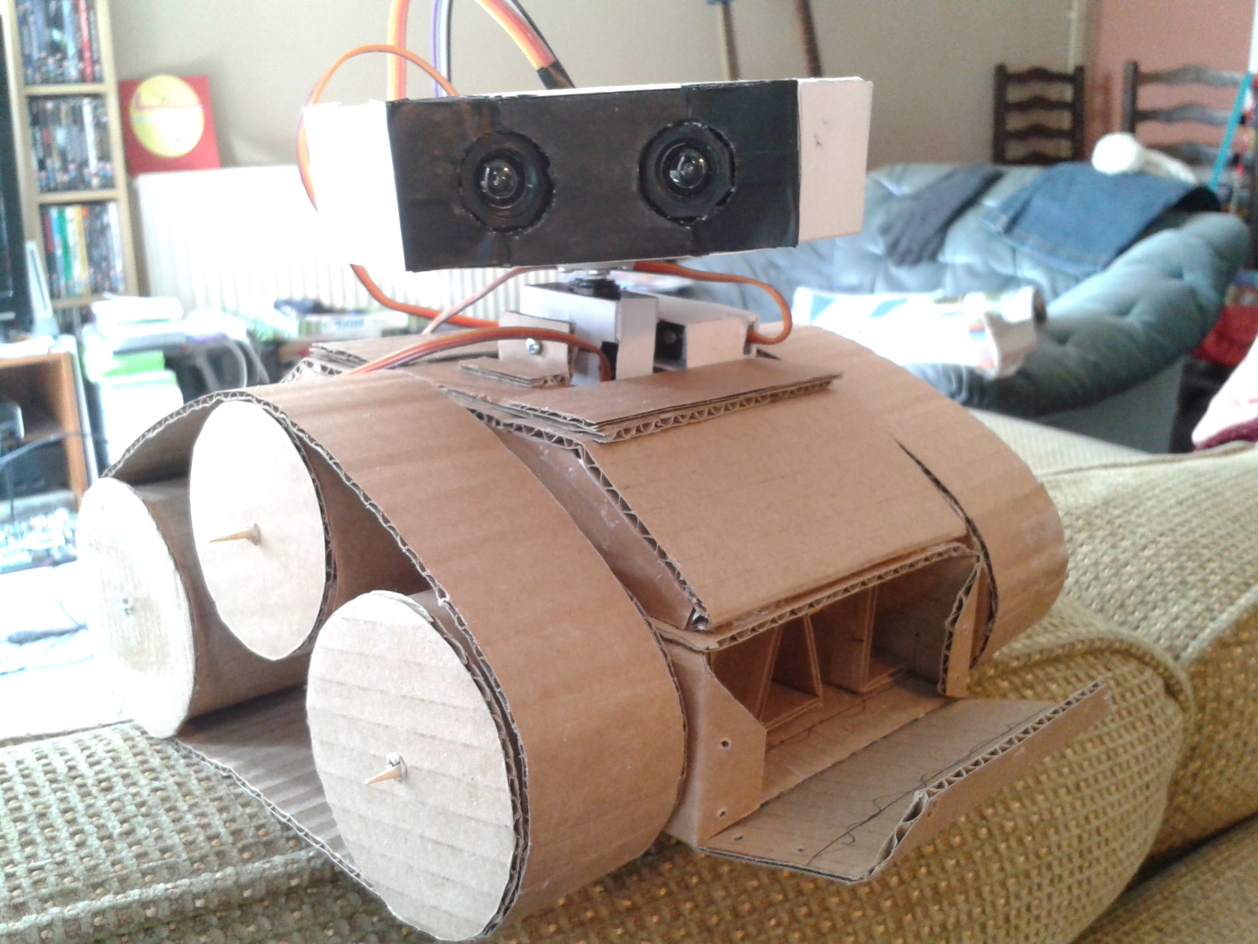
Interface it to the existing Origaime hardware and I'm now nearly ready to proceed where I left off due to the servos.
Life imitates art, a Wall-E made of trash :-)
The neck pitches and turns, the eyes focus and it will move on its tracks when I get the motors wired in.
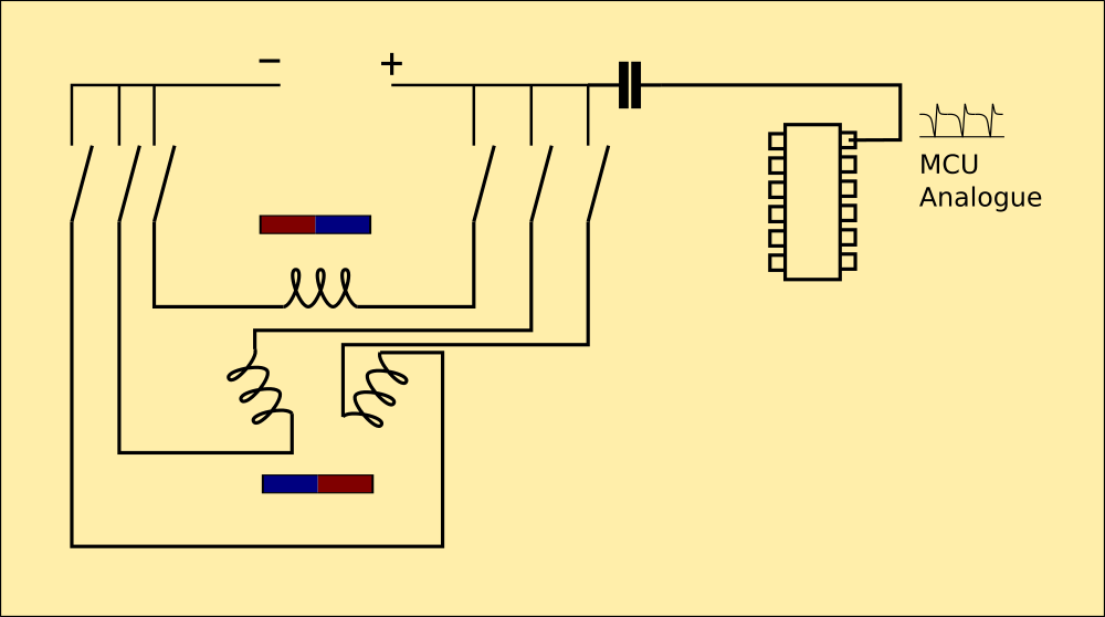
Because they are DC motors I'll need to find a way to sense their position for basic metrics. There is no room in the gearbox for a magnet near the motor output shaft or any other way to read the motor revolutions. I could rip up an old mouse and use the encoders, but I've come up with an interesting alternative.
As the motor has a commutator it throws out a lot of EMF and needs suppressing. While I'm in there, I may as well sense the back-EMF using one of the MCU's analogue inputs and use that to determine rotation. I havent tried this yet, but I'm optimistic.
Origaime (Cardware-bis)
An educational system designed to bring AI and complex robotics into the home and school on a budget.