Dr. Cockroach
-
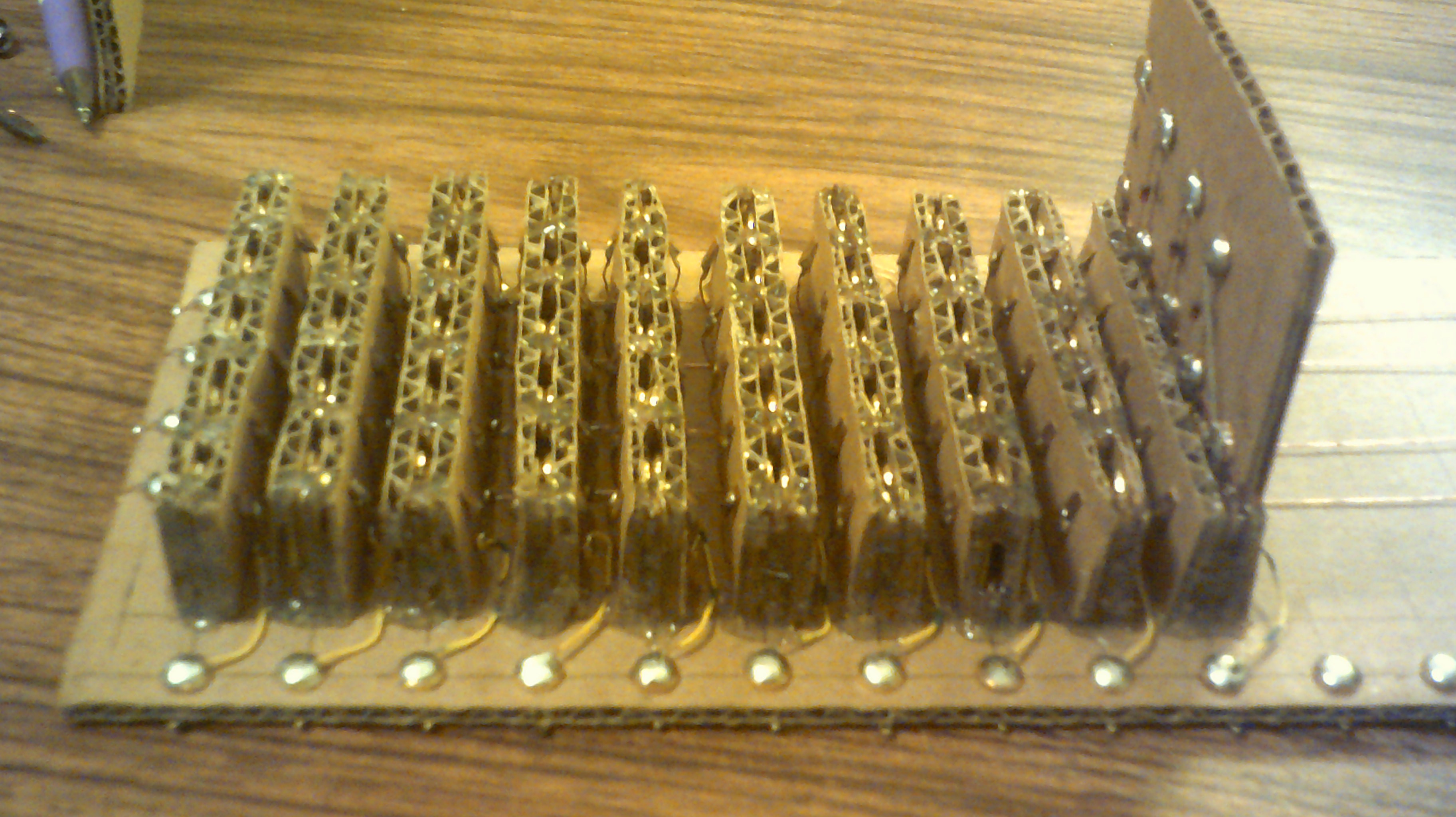
A major re-design - February 28, 2018
02/28/2018 at 18:53 • 9 commentsWell, the Brainwarp panel using magnetic placed instruction cards has hit a major snag. The card contacts do not make contact as consistently as I need so a re-do is needed.
I have come up with a back-plane with edge card connectors that will be used for the instruction cards. All while still using cardboard and paper fastener construction. Lots of hot melt glue is used for this build...
Here
![]()
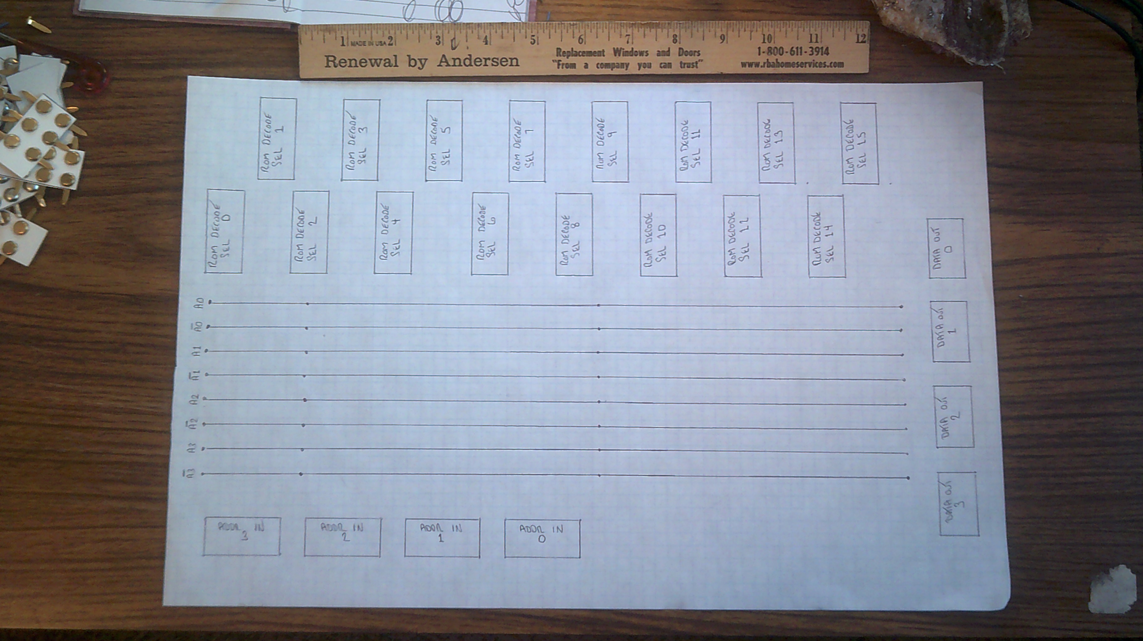
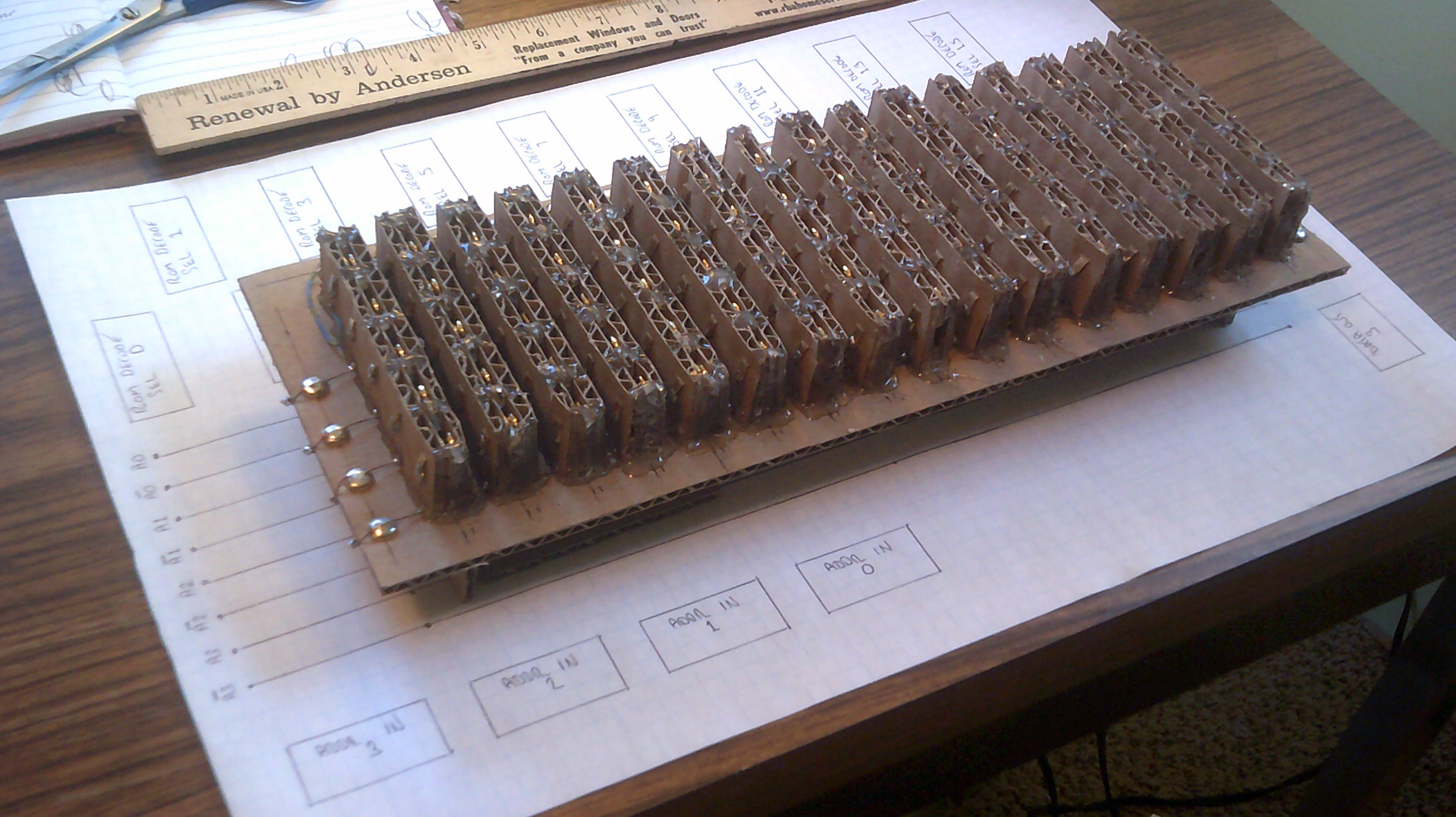
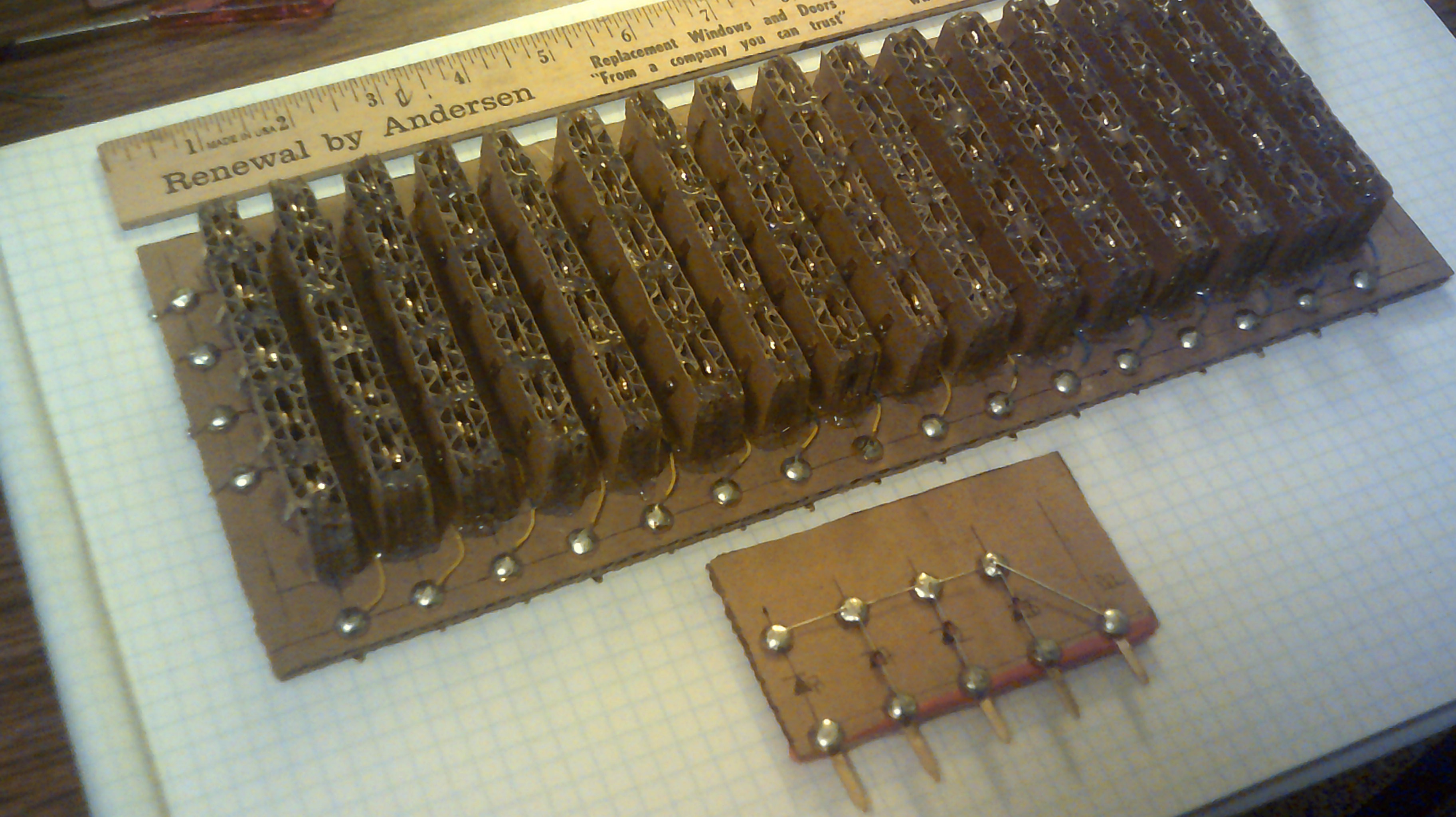
Well, here is the finished Back-plane with 16 four bit ROM slots. Next is to wire up some more ROM cards and the address logic board and it's all set.![]() Here is the basic layout for the ROM logic board. The ROM back plane will mount above.
Here is the basic layout for the ROM logic board. The ROM back plane will mount above.![]()
![]()
-
April 30, 2017 - All eight instructions lit up
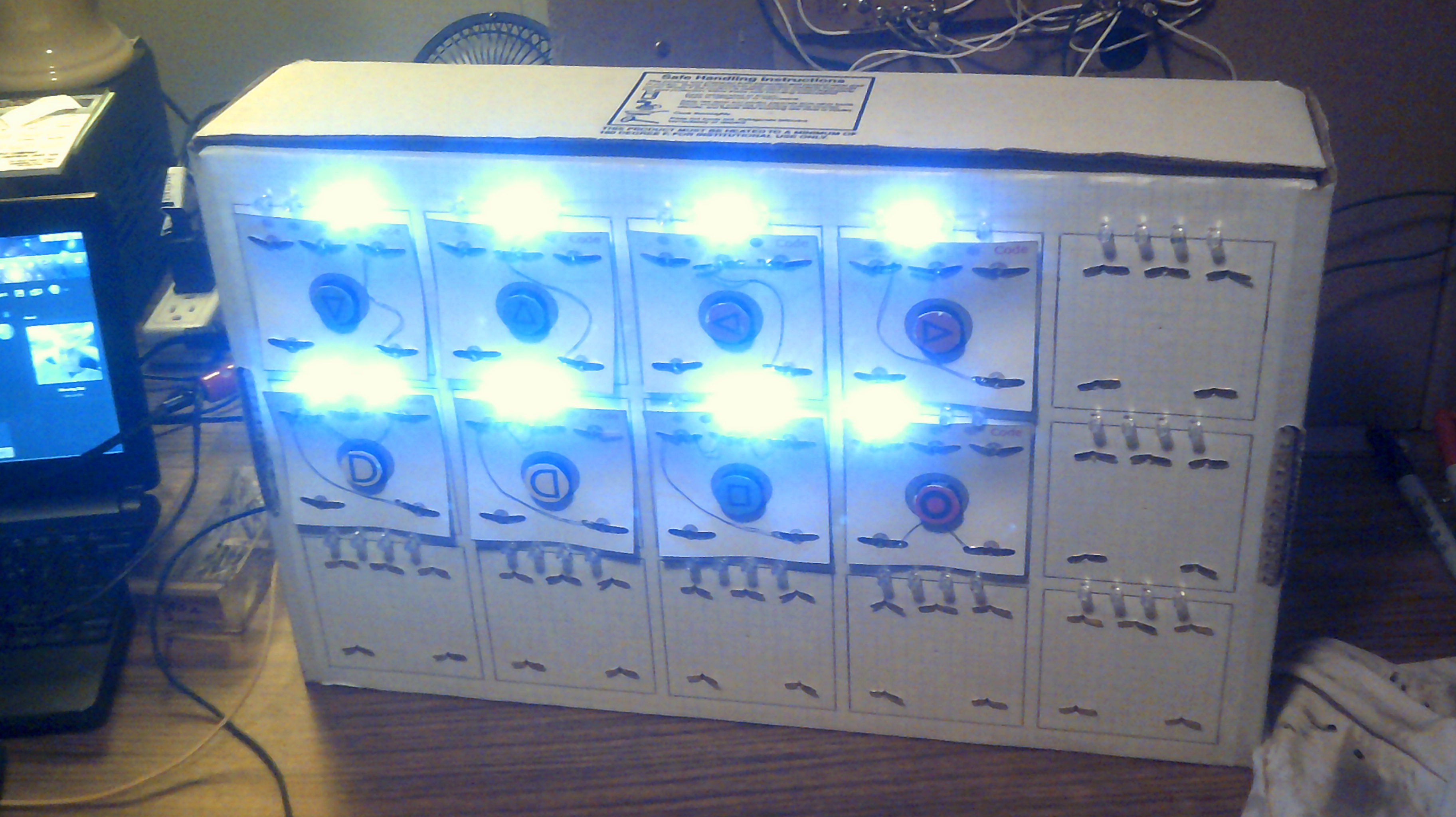
04/30/2017 at 08:00 • 7 commentsGetting the panel wired up more and more. The panel read logic will be next for this build.
![]()
However, the temperature required to operate this panel might be too much for the person programming it ;-)
![]()
-
April 21, 2017 - Instruction Card revised and the Instruction Set
04/21/2017 at 19:49 • 0 comments![]()
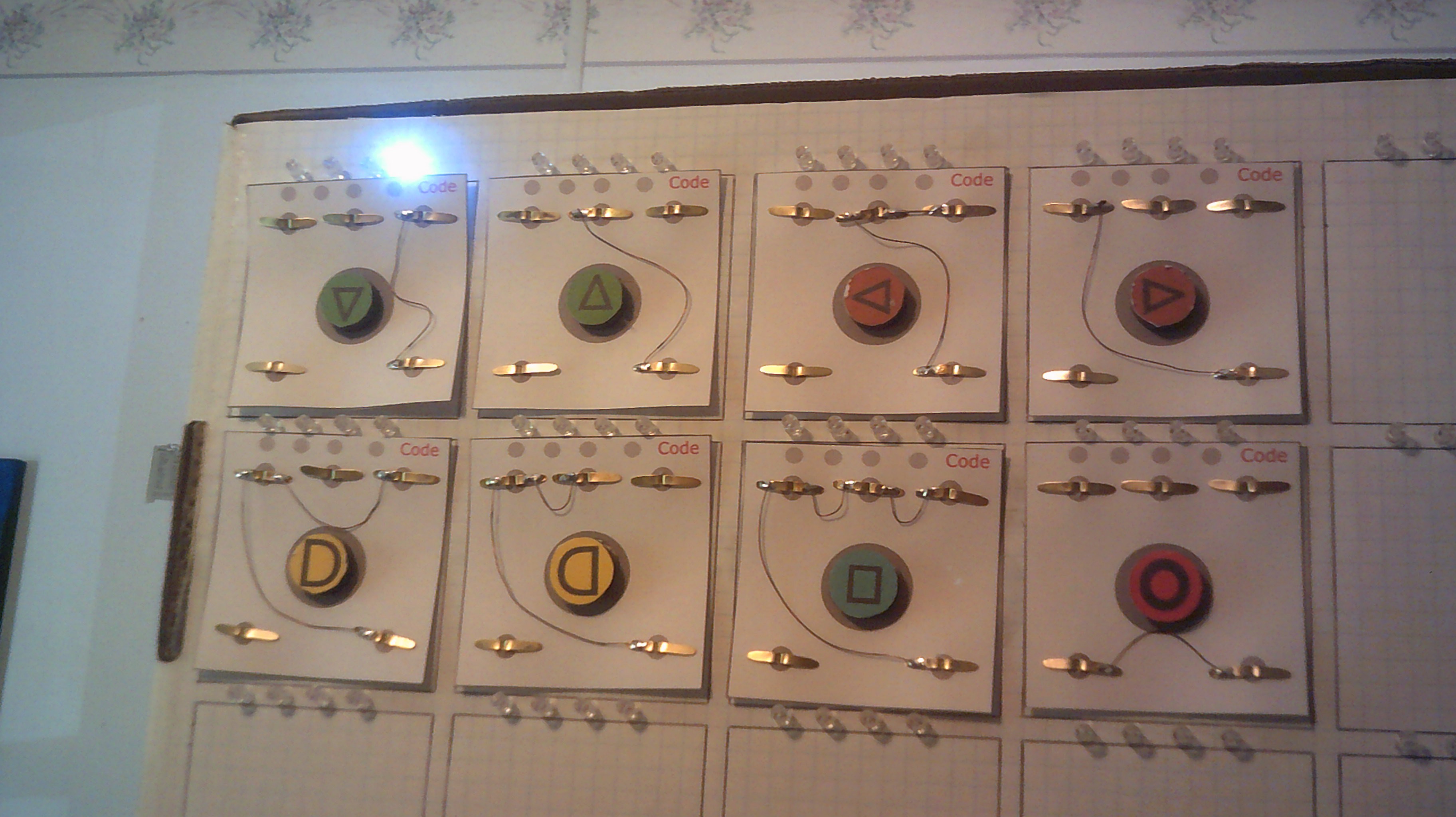
I have found out that after several cards were constructed that the cards were too stiff and warped out of shape enough to not give me a correct read every time. I have gone back to a simple design that gives a view of what is going on with the circuit and the magnet serves as both a graphic presentation of the instruction but also serves as a grip for placing and removing the card from the reader panel. I still need to wire the rest of the panel.
The Instruction set reading left to right , top bottom
code - instruction
1 - Subtract one from the current cell value
2 - Add one to the current cell value
3 - Move pointer back one position
4 - Move pointer forward one position
5 - Begin while loop
6 - Return loop until current cell = zero
7 - Input value to current cell
8 - Output value from current cell
All cell values are set to zero at the start of a program run. -
April 15, 2017 - Cardware construction of the instruction card
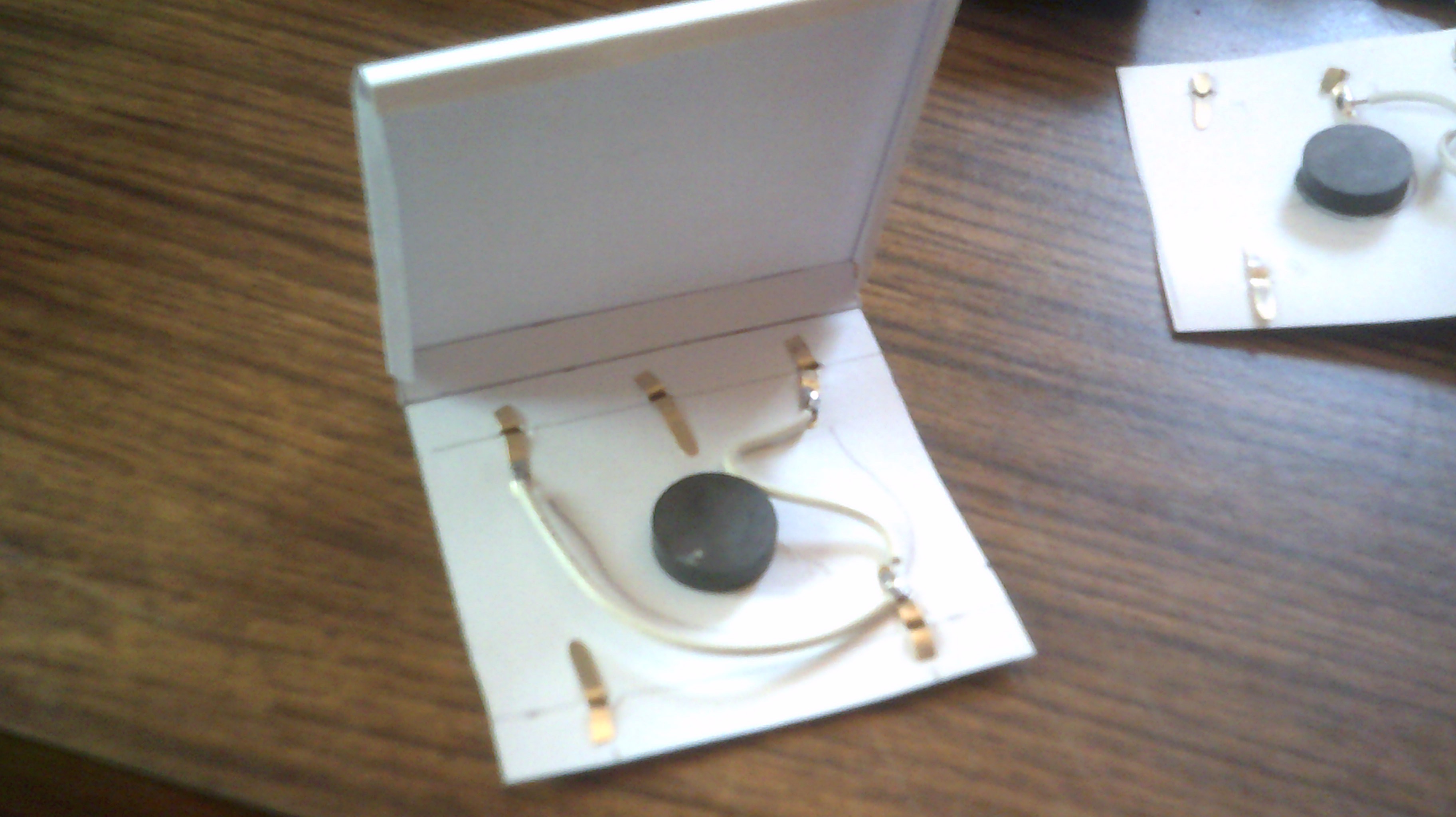
04/15/2017 at 19:04 • 2 commentsThis is the latest version that uses the #Cardware method of enclosing the instruction card. I also have found some ceramic magnets that have greater holding pressure and this results in a solid contact.
![]()
![]()
This card is wired for code 5 - Move pointer right one position
![]()
-
April 14, 2017 - Improved card to pad contact
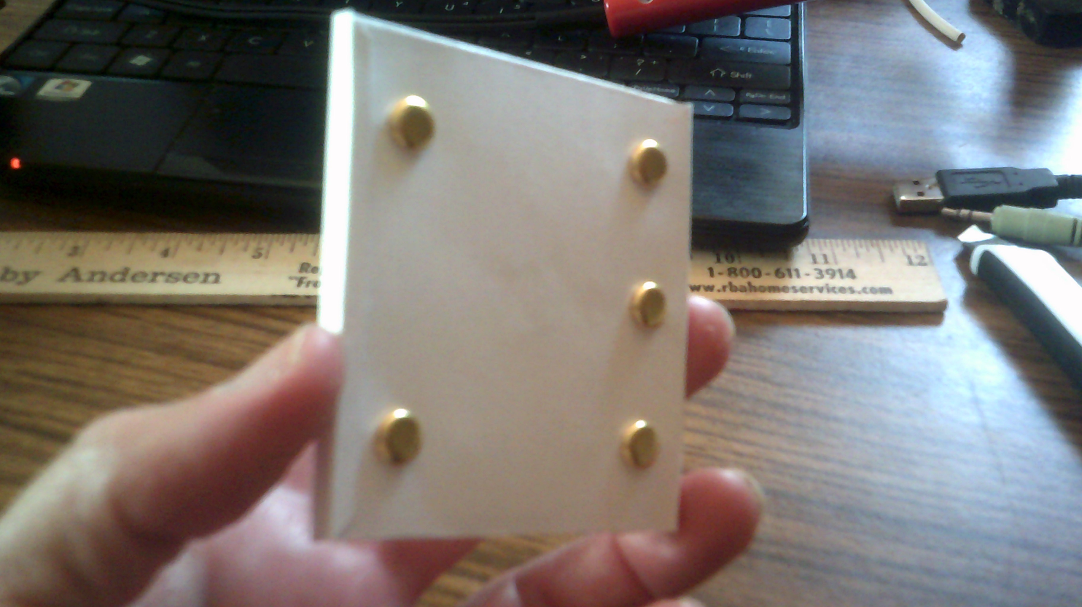
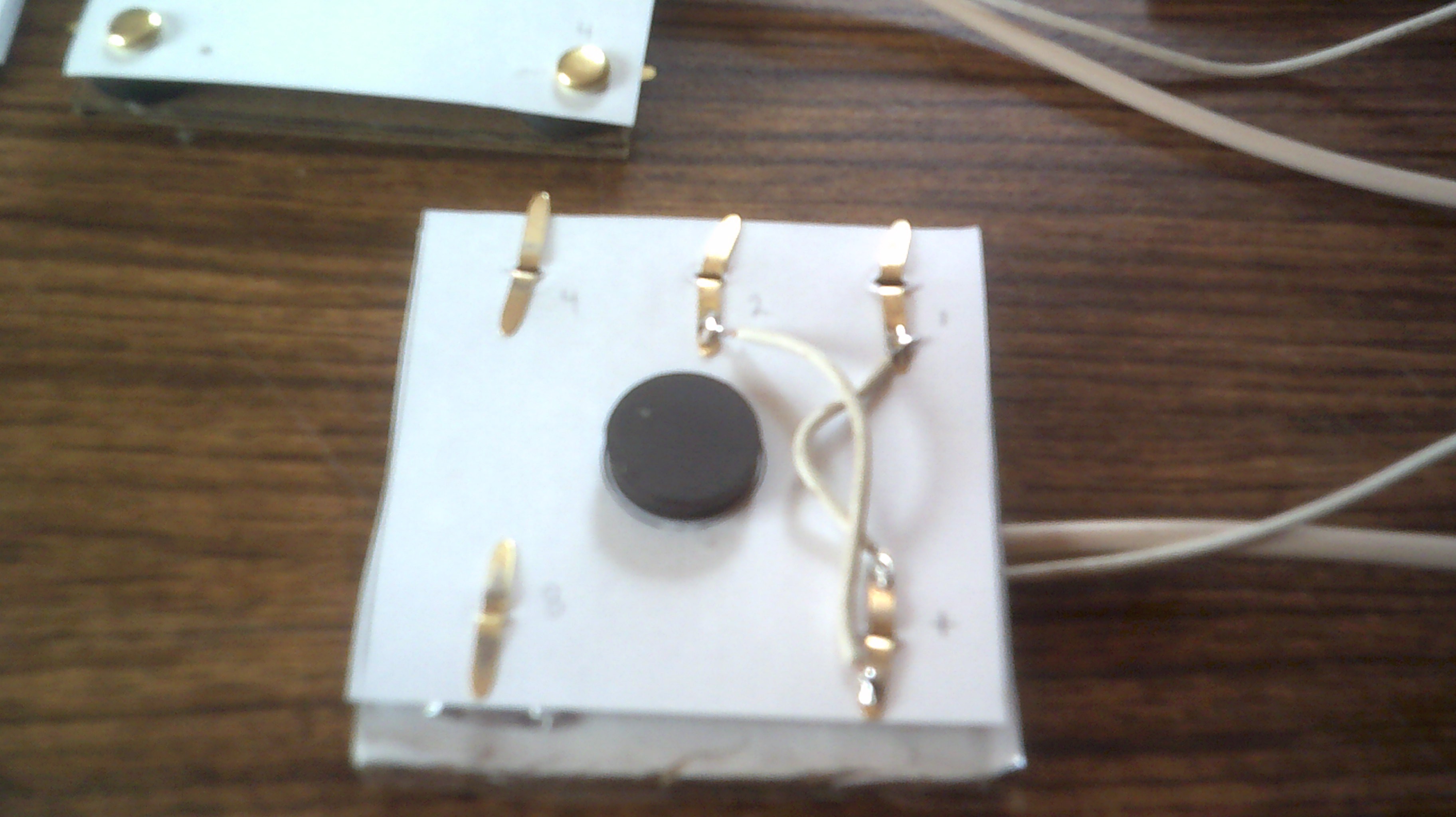
04/15/2017 at 00:26 • 0 commentsI was using some very weak magnets from the local big box store to provide the holding power needed to keep the card is contact with the reader pad. The first version was not making anywhere near 100 percent correct contact and it was decided to rearrange the contacts and use one set of central magnets. I found some ceramic magnets that provide the holding pressure needed and with the new contact layout, I now have a 100 percent correct contact rate. The photos below illustrate how the card and pad are constructed.
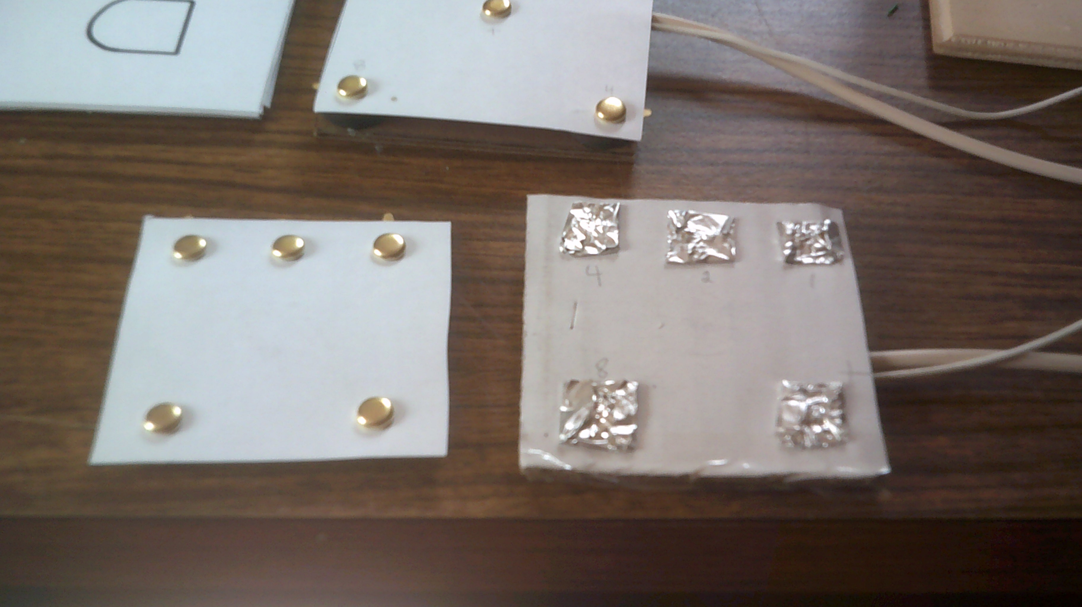
The foil pads are kept in place using the brass fastener tabs as hooks. The wiring is simple enough. One contact is +5 volts and the other contacts are the binary outputs to the test leds in this case. The magnet for the reader pad is hot glued to the bottom and in the center
![]()
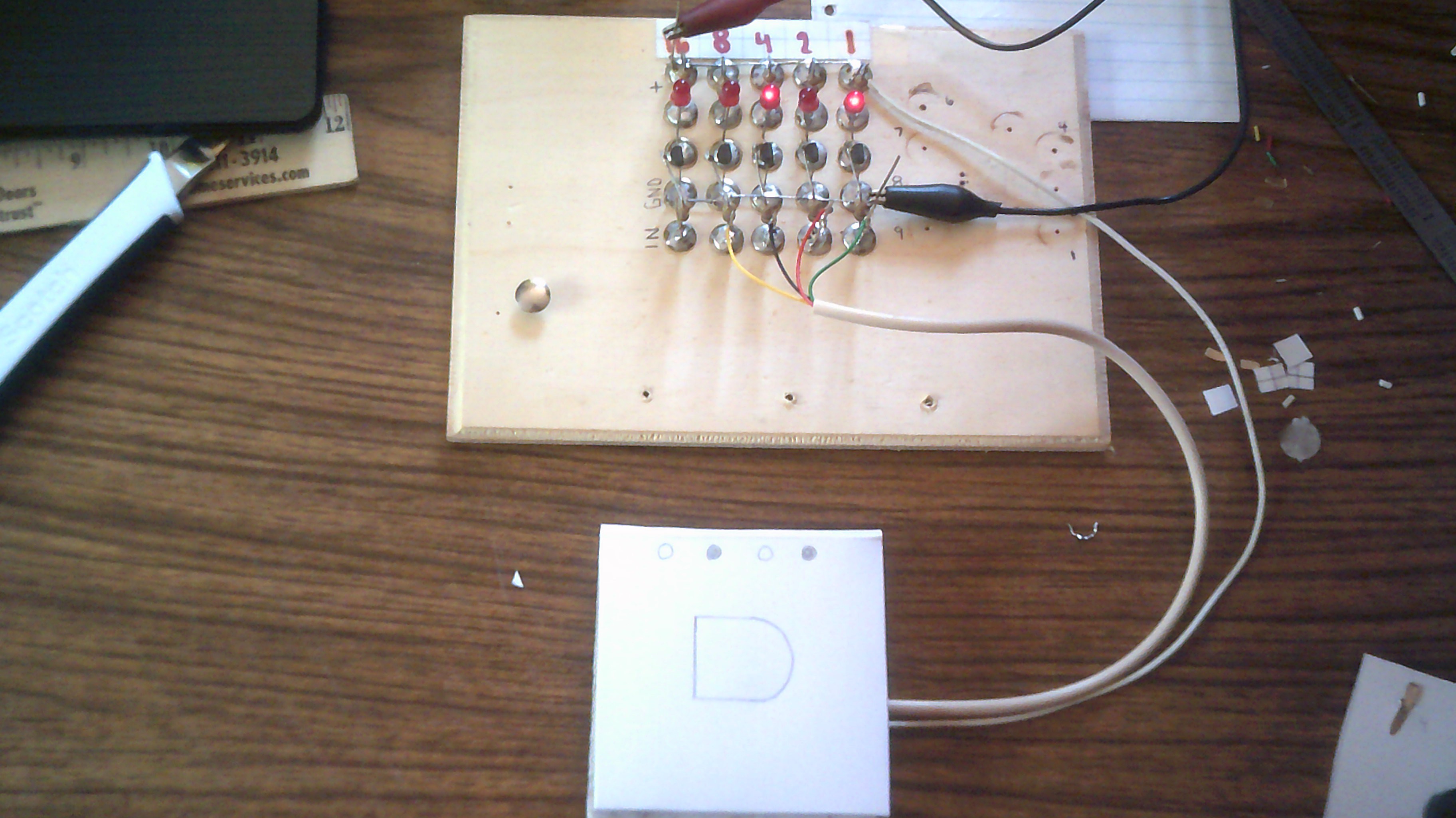
When the instruction card is placed onto the reader pad, the magnets hold the card in place and the brass contacts make solid contact with the foil pads. A cover with the needed graphics will be added to the instruction card.
![]()
-
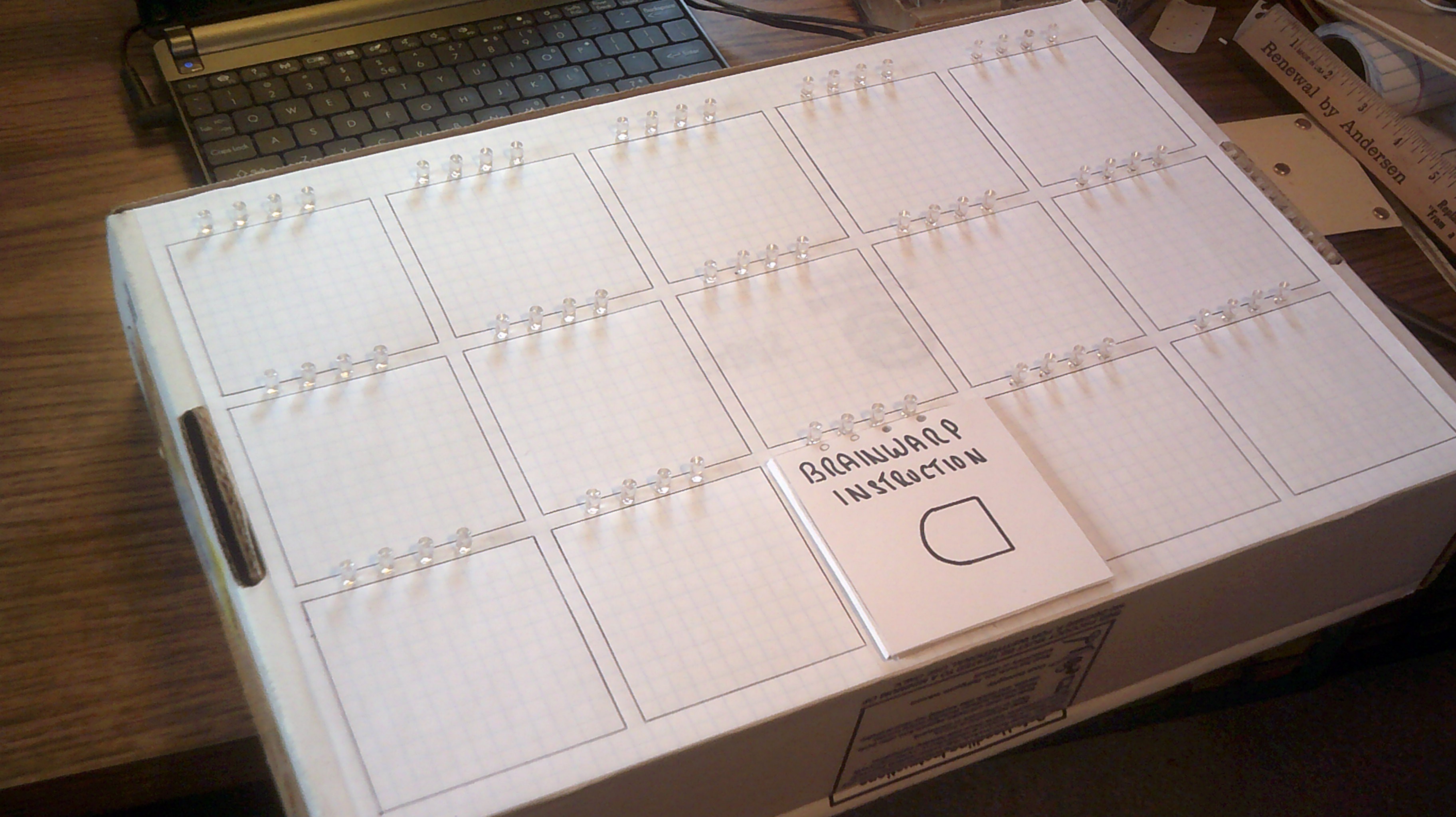
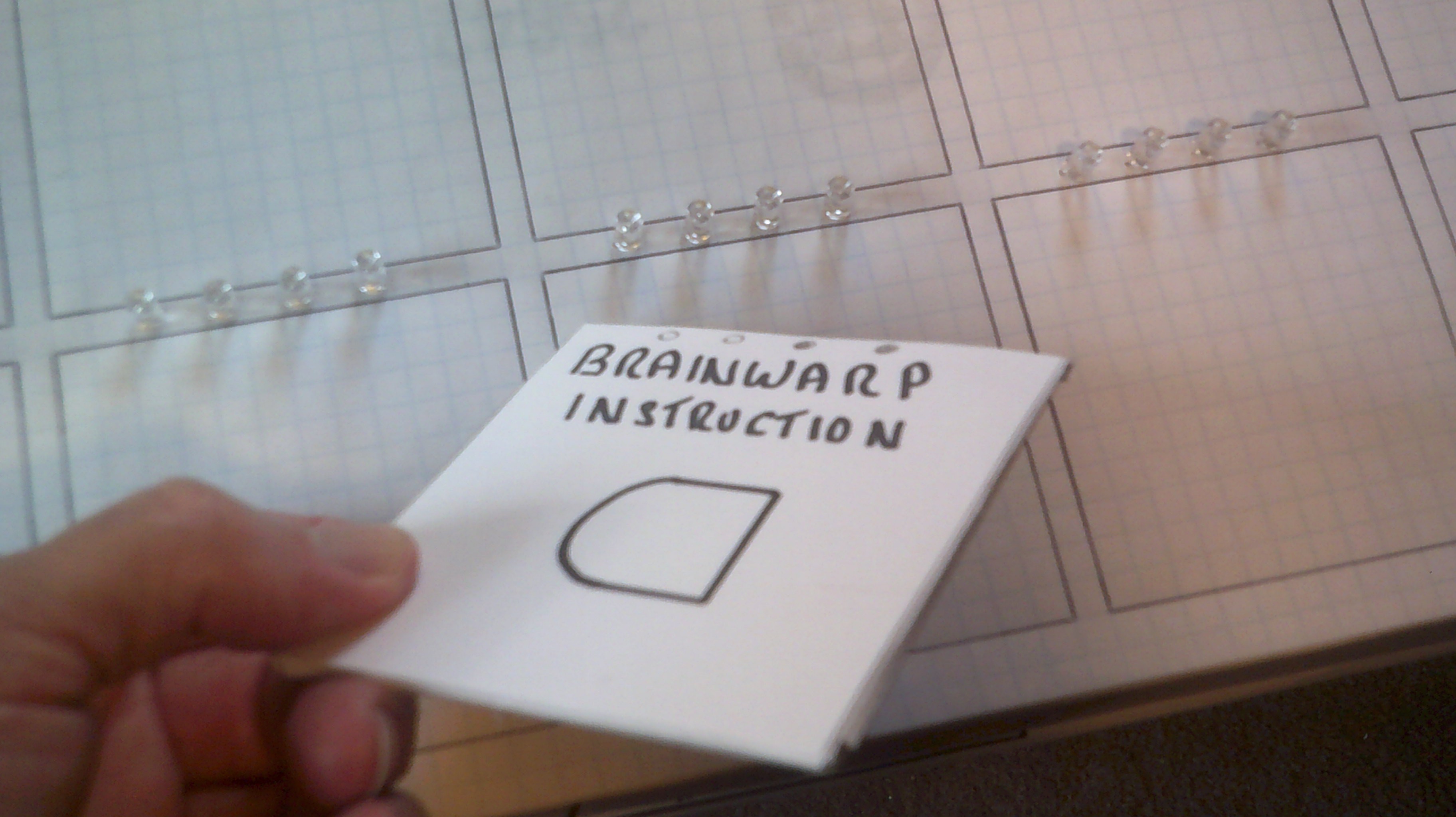
April 12, 2017 - Brainwarp Entry Panel Mock-up
04/12/2017 at 23:58 • 0 comments![]()
![]()
Brainwarp - Program entry panel
A design for a program entry panel that uses tiles for instruction input.
 Here is the basic layout for the ROM logic board. The ROM back plane will mount above.