 Pavel
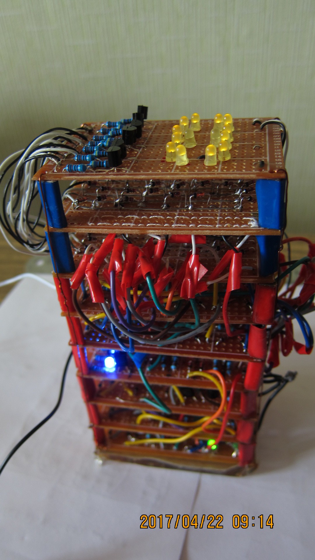
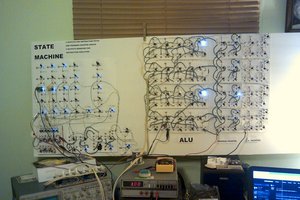
PavelCounting circuit consists of modified astable multivibrator circuit with three NAND, master-slave data flip flops connected as series toggle flip flops, thus I have 4-bit counter. The dtl gates have LEDs instead of pairs of conventional diodes to slightly save on part count and cost. In addition, this scheme provides visuals for gate working.
0%
0%
Simple counter/clock
4-bit counter hooked up to 7-segment display showing succession of hexadecimal digits
Become a Hackaday.io member
Already have an account? Log in.
Just one more thing
To make the experience fit your profile, pick a username and tell us what interests you.
Pick an awesome username
hackaday.io/
Your profile's URL: hackaday.io/username. Max 25 alphanumeric characters.
Pick a few interests
Projects that share your interests
People that share your interests
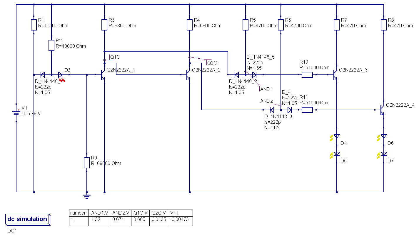 collector of Q1 was wired directly to base of Q2, to achieve second inversion, thus making buffer; simultaneously from the same collector was the tap to the AND gate of decoder, as inverted input. Failed. the solution was to make this into two full-fledged invertors, and after this modification all started to work as it was intended to.
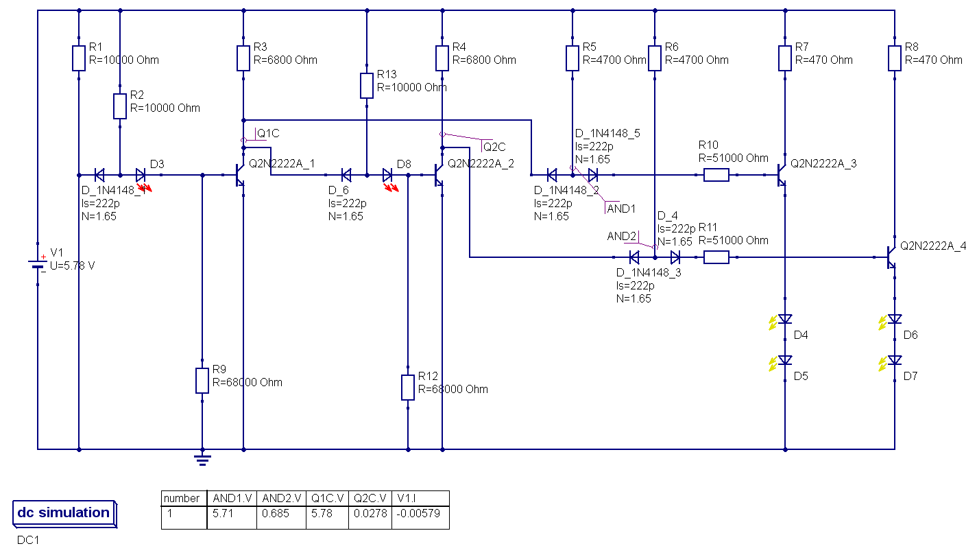


 Dr. Cockroach
 will.stevens
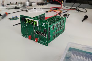
 Jesse Farrell
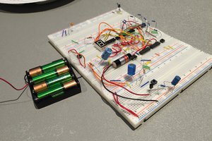
 Dylan
Dylan
Very good project :-) Almost the same issues I have had. Keep going :-)