-
Finished!
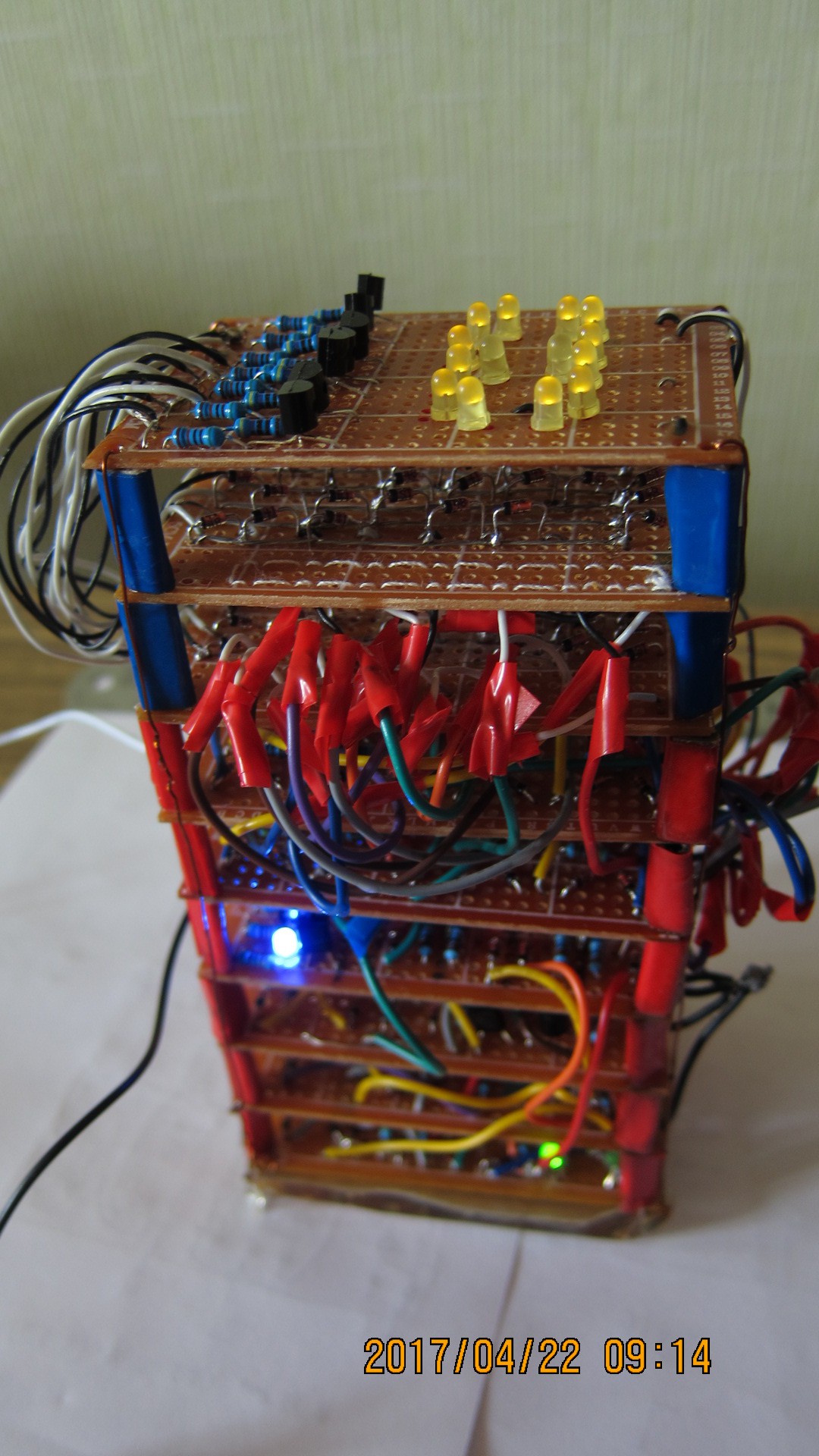
04/22/2017 at 08:00 • 1 commentThe thing is now complete and working!
-
Solution is found!
04/20/2017 at 03:56 • 0 commentsThe humble diode AND was not to blame after all, it was prior wiring that was faulty.
Here are simplified schematics with voltages:
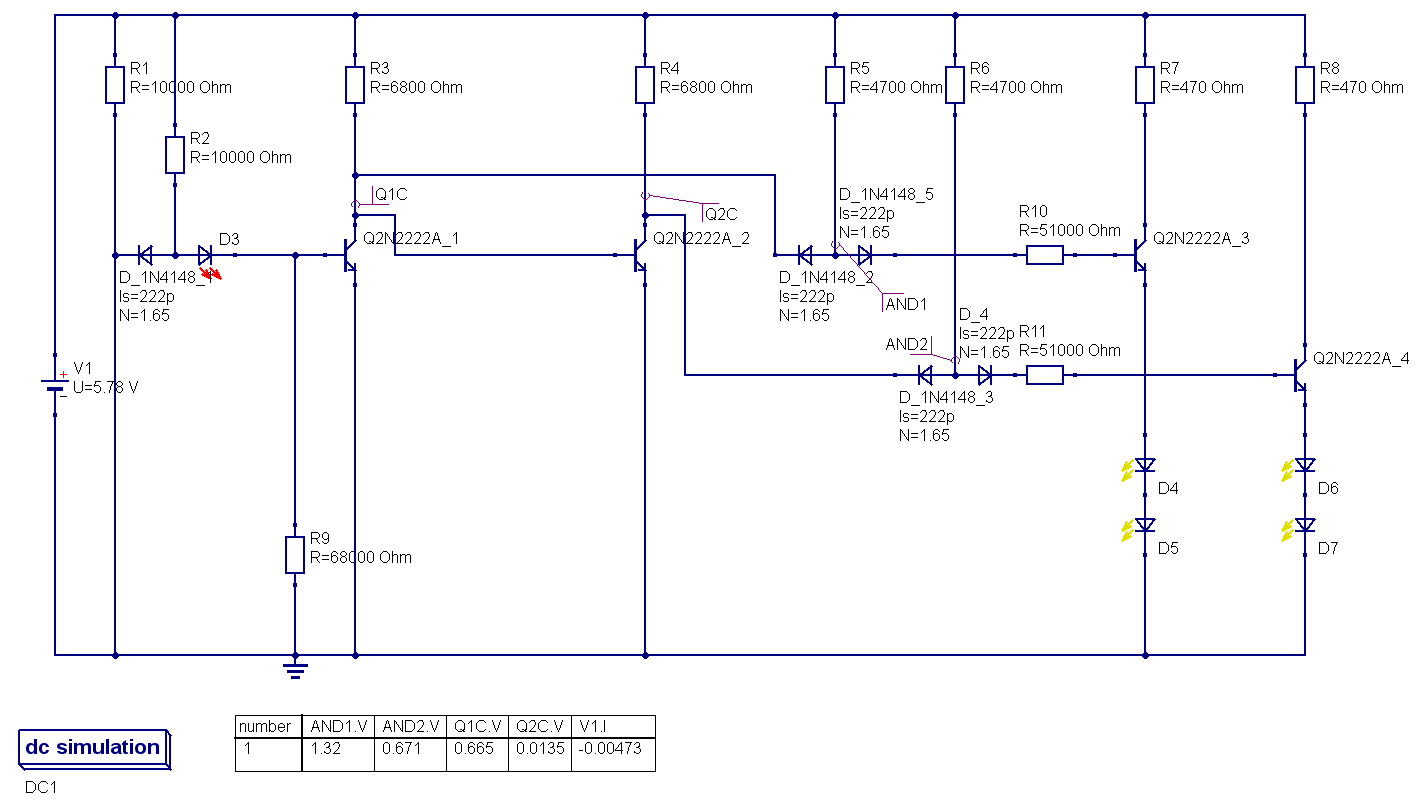
1) original wiring:
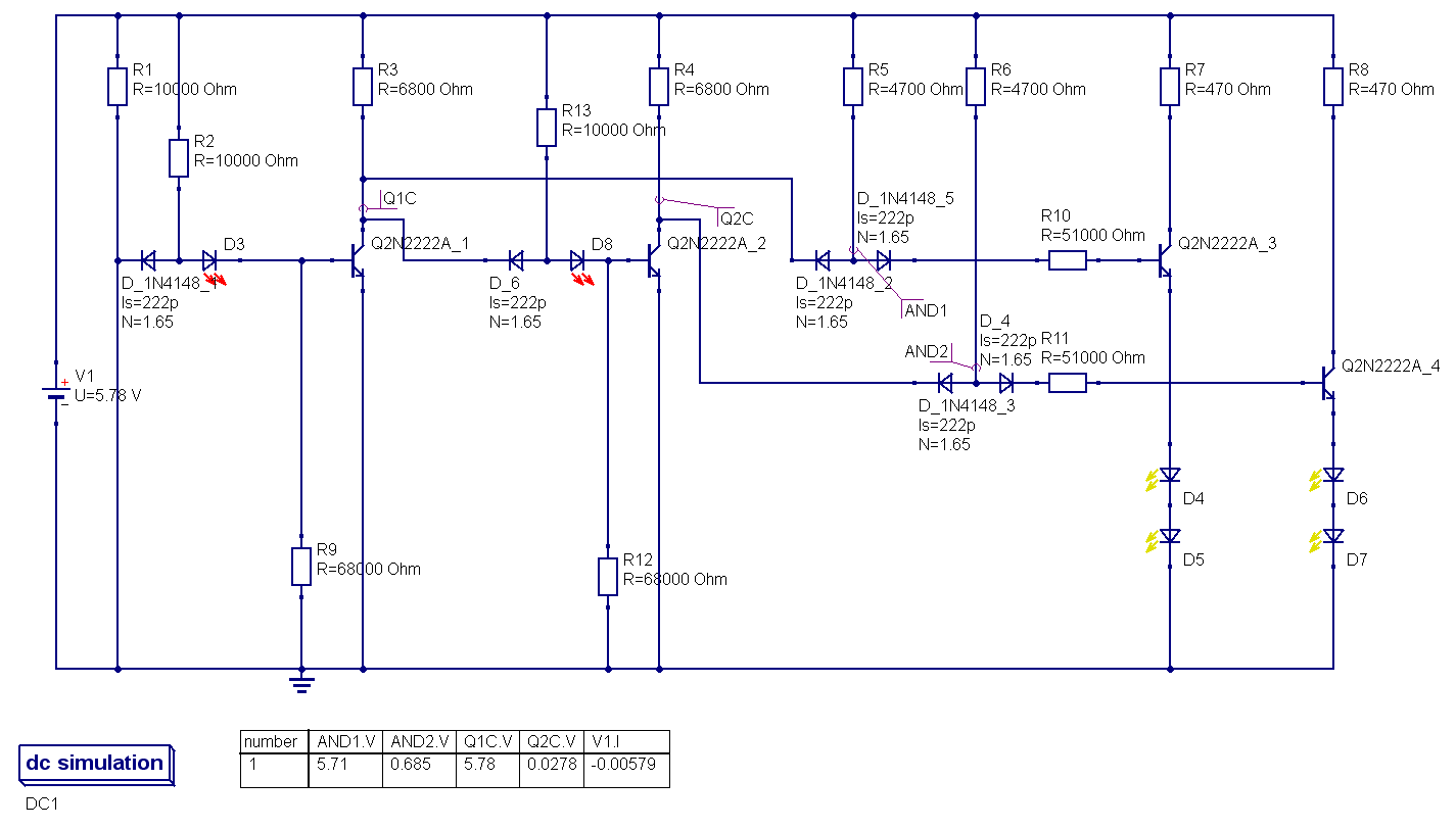
![]() collector of Q1 was wired directly to base of Q2, to achieve second inversion, thus making buffer; simultaneously from the same collector was the tap to the AND gate of decoder, as inverted input. Failed. the solution was to make this into two full-fledged invertors, and after this modification all started to work as it was intended to.
collector of Q1 was wired directly to base of Q2, to achieve second inversion, thus making buffer; simultaneously from the same collector was the tap to the AND gate of decoder, as inverted input. Failed. the solution was to make this into two full-fledged invertors, and after this modification all started to work as it was intended to.2) corrected wiring:
![]()
-
Problem with output logic levels
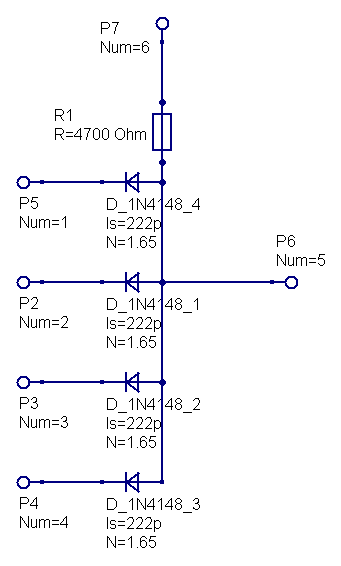
04/14/2017 at 04:51 • 0 commentsFor decoder I used simplest diode 4AND logic gates (image), assuming they would work properly, and give +Vcc for high and 0.6V for low.
![]()
Unfortunately, output for HIGH is measly 1.6-1.7V and it is too low for driving display unit.
I am still cannot understand, why is it so.
Simple counter/clock
4-bit counter hooked up to 7-segment display showing succession of hexadecimal digits
 Pavel
Pavel
 collector of Q1 was wired directly to base of Q2, to achieve second inversion, thus making buffer; simultaneously from the same collector was the tap to the AND gate of decoder, as inverted input. Failed. the solution was to make this into two full-fledged invertors, and after this modification all started to work as it was intended to.
