-
Summary
10/21/2017 at 15:46 • 0 commentsThis is the last project log. It will be a small compendium where i describe what i have learned in past half of a year.
Printheads
I have made replaced the xaar printhead with hp45. I had struggled a lot with it as it has smaller drop sizes. This means that it is harder to wet the base material properly. This is why I have decided to use Xaar128 on the final design. It is also a lot easier to use.
Materials
I have worked with a lot of materials. Besides the wetting properties and structural properties I was also working on sintering properties. I have found out that for sintering you want to slowly (100°C/h) heat up to the temperature a bit lower than the melting point of the material. Have it at this temperature for at least an hour (this increases shrinking and final density). Then cool it down at the same rate.
I made the printing materials from:
- Ceramics powder
- Magnet dust (SrFe12O19)
- Bronze blend
- Titanium powder
- Hydroxyapatit
Binder
I found out that methyl cellulose works very well as a binder and it can be easily used with any of above materials. Only problem I have encountered with it is when I was sintering at temperatures lower than 1000°C. It didn't burn away properly and it has left carbon everywhere. I was mixing it at about 10% of mass of material dust (1g of methylcellulose/10g of final mixture). It depends on the density of material so for titanium i had to use a bit more (15-20%).
Metals
When using metals keep in mind that they can oxidise when particles are small enough (especially with aluminum, this is also a reason why I didn't work with it). They can be easily printed with but problems do appear when sintering. You need an inert gas when sintering, this is a must. Even with argon few samples of titanium oxidised.
Alloy blends are not viable option as they wil not mix. This will leave you with samples that look beautiful but are completely useless.
If you want metal parts from this kind of printer you will need to infiltrate them using some other metal (bronze).
Magnets
First things first, the magnets were ferrous, this means that they are a lot weaker then neodimium. I have used SrFe12O19. It prints really well even though it tends to clump up. There is one problem, it is very dirty (if this stuff touches any surface it is going to get stained by a very dark shade of brown). There is also a nice thing about using it where one does not need to sinter it as it can be infiltrated (filled with epoxy or glue). They need to be magnetized at the end.
Ceramics and hydroxyapatite
Theese two behave very simmilarly. You need to sinter them at T>1300°C. If they are not sintered well they will be very crumbly. Otherwise they are a really good starting point as they do not oxidise. The only downfall is they have a high sintering temperature.
-
Web UI printer interface
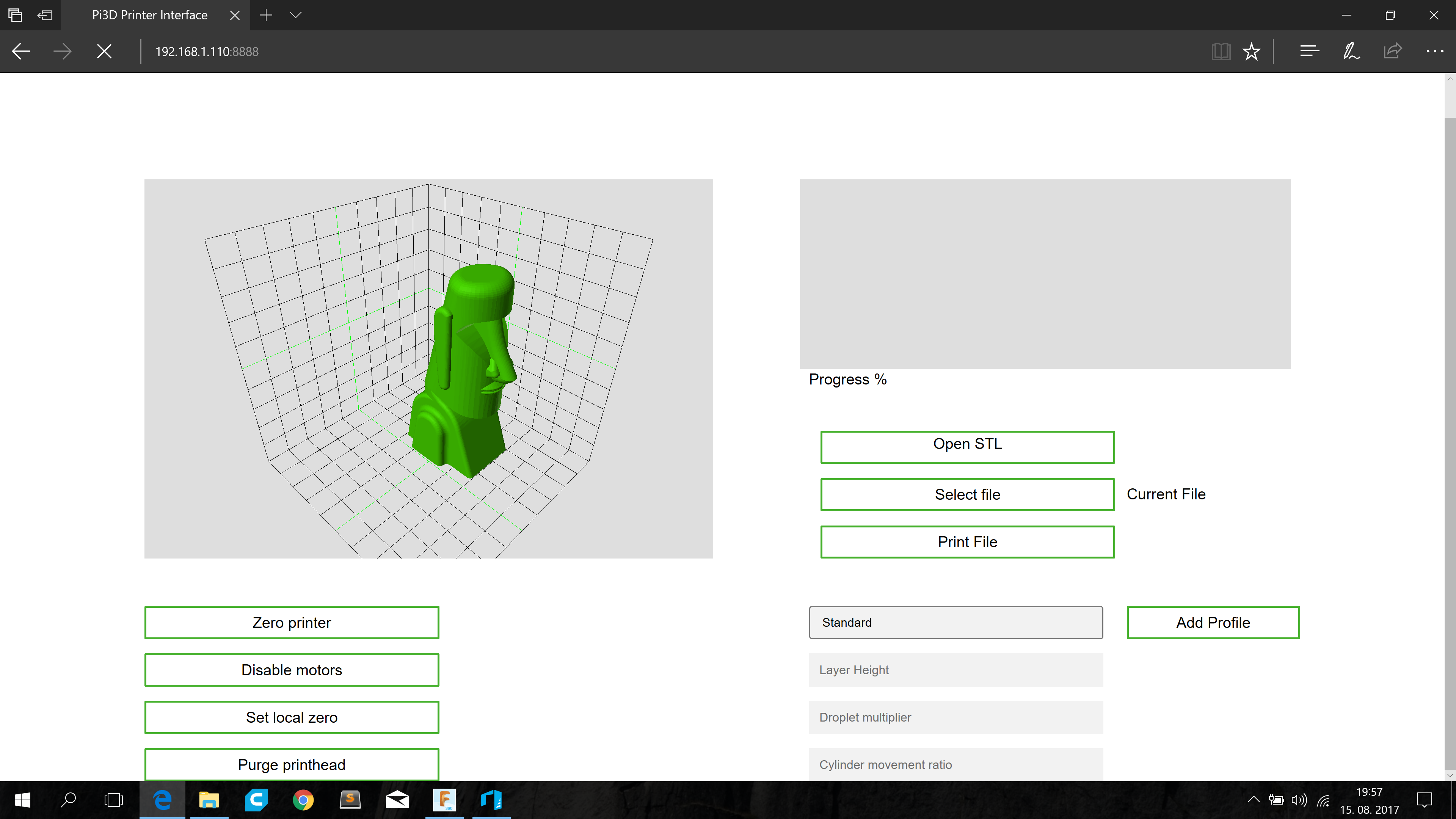
08/15/2017 at 18:18 • 0 commentsWeb UI was one of my primary goals for this project. I think it simplifies a lot of things as it omits the use of any additional software therefore it eliminates any conundrums with instalations or libraries. This is why I have developed a basic UI with main settings and parameters. It is based on python and tornado so it could run on almost every current single board computer. This allows any end user to choose according to his/hers preference.
There are still few things missing but currently it looks promising. It still needs a progress bar, print info, estimated time, elapsed time. It also needs ability to store settings and configurations to xml and then read them. Another good thing to implement is model movement and rotation (most likely it is going to be step based). I still need to add the option to manage and select the files stored on the printer itself. Currently I am working on getting the page at the point where it is synchronous with printer (printer status, model loaded, etc.).
I have also decided to add a picture of the current page design (I like it quite a bit, due to its simplistic look). In its current state it is able to send commands to the printer, has a model preview and has the ability to add new setting presets (just temporarily, still needs an xml file IO implementation)
![]()
-
Broken
07/29/2017 at 18:40 • 0 commentsThis week I have been focusing on getting the new printhead up and running, but without success. The HP45 is a fantastic little device from beginning of the last decade, yet it is delicate and hard to operate from my point of view. It has a 22 address lines and 14 primitive lines along with bunch of ground lines and a thermistor and reference resistor. Both the address lines and primitive lines form a 14*22 matrix, that yields 308 usable outputs of which 300 are used for nozzle heater resistors and 8 of them are not connected. All the inputs function at 12V, but the primitives also accept lower voltages to regulate the nozzle drop characteristics. The primitive lines need more current as they power the heater elements in the nozzle.
I am using the YTec3D hp45 controller. It has 2 subunits, where one is just a set of 4017s along with AND gates to increase their range. They are used to trigger between different address lines. The second unit consists of two TLC59213 latched led drivers. They supply current for the nozzle heating elements.
After numerous hours of bugfixing, troubleshooting, etc. I found that the problems I have encountered are caused by bricked TLC59213s. It is also interesting that both have 1 latch bricked. Furthermore the broken latches trigger the primitive line 12 and 13. These lines have neighbouring bins, so this indicates a problem on my side. Funnily enough both of bricked latches work alright with the CLK and RST pin but they just ignore the input pin.
I will order the new part from farnell, so I will be able to replace the chips on tuesday (hopefuly).
New design?
Few weeks ago Formlabs announced their Fuse 1 printer. Luckilly enough Tested (http://www.tested.com/) did a video on this printer. I have watched the video for couple of times just to get some ideas. Upon seeing and thorougly analysing the video and printer itself, I got some of the Ideas that I am going to include in my printer. The main feature I am going to add is a detachable bin (probably around 150mmX150mmX300mm) with a storaged powder deposition system. This way the loading and unloading of the printer are going to be much easier. Also it will be better for the system with any upcoming materials, as it will minimise the dust falling onto the rails.
-
Version 1.1
07/19/2017 at 21:53 • 0 commentsThis week I was able to get most of the prototype electronics together. Last few days I have mostly worked on getting the firmware and software up and running. I have also made a ceramic powder that might work with the printer. So if everything goes according to plan, I will be printing with ceramics next week. Then I will get the parts printed parts smelted so I can do some testing of strength, etc.
Current electronics consist of two lm298 h-bridge drivers (one could be replaced by a normal stepper driver) , a pololu stepper driver, 2 maple minis 2 encoders with simple voltage dividers. Current system looks rather promising as it could be already used without any additional controller (it would lack any interface and the usage would be rather limiting, as user could not select a file from a SD card. I am still working on getting software on Beaglebone together (it is rather hard for me as i am new to beaglebone and especially PRUs on it). For now I have modified previous python program to open an svg and then export it to .pbip file (stands for Powder Bed Inkjet Printing) which is just a bunch of run length encoded nozzle data that is 'synchronous' to the printing protocol (data is in the same order as printer needs it). This could then be also used as somewhat of a universal system if the file is going to be reliable enough. This would also allow for easy replacement of SD card with an SBC as only changes to communication would have to be made (10-20 lines of code)
If everything works as it should I will make custom pcbs. I will probably draw them in single sided version and double sided version, so they can be ordered or even made at home (I know I tend to make a lot of promises, but I have decided not to upload everything from previous versions as it had a lot of bugs. I will upload almost everything when a design prooves itself as stable)
I hope I will be able to upload few photos or even a short video of functioning printer.
-
I am back
07/12/2017 at 20:37 • 5 commentsOn monday I have received the results of the exams I had in past two months. This also concluded my high school days and started my almost 3 months long break. This means I will have a lot of free time to work on this project.
Even though I had final exams spread across the last few months, I did some work on this project. I managed to get parallell drive belts on the y axis, add a servo to drive the x axis. I also calibrated the PIDs for both servos. I added limit switches for x and y axis. The HP45 mounts have also been made and attached to the 3d printer.
Currently I am working on making everything working together. I am also trying to keep everything as clean as possible to be easy to read. Finally I decided on printer to work via web interface, this means no switches, displays, ... (maybe a status led or two). I think this is quite a nice feature as it increases simplicity for the end user. This also makes the printer controllable via tablets or phones (currently it is somewhat useless, but later I/someone could implement a function where user could print things directly from thingiverse or some other site).
I am also working on making new materials for printing. Currently I am focusing on printing with technical ceramics. I have also decided to drop development on hydroxyapatite for now (it is too expensive/hard to produce and rather useless for now).
Also I bought my first 3d printer (150$ replica of geeetech prusa i3). I have done some substantial upgrading like extruder replacement (makeshift version of e3d titan). Now it prints comparably to a Makerbot. This FDM 3d printer also allows me to make this project more friendly for those who don't have a cnc.
-
The future
05/12/2017 at 20:27 • 0 commentsNext few weeks are going to be rather hellish. I am having my final exams at the end of may, where I will be recaping everything I have learned in 4 years. This is why there will be irregular logs, where I will be talking of what I have managed to do. I will be trying to finish on some basic upgrades. In June i am planning to continue on material research part of this project (mainly ideas posted in comments, PVA as binder and probably usage of currently researched additives on other powders).
Hopefully I will be able to finish the replacement of printheads and addition of SBC in one to two weeks. These are currently the hardest for me to do, so mistakes, bugs and errors are bound to hapen.
I will be also focusing on uploading files for current version of the printer to A360, so everyone can se how I made the printer.
-
Main controller AKA motion controller
05/11/2017 at 19:56 • 0 commentsToday I have been focusing more on completing the firmware of main controller. It is nothing more than movement synchronization, zeroing and movement control algorithms. I am using STM32F103BC microcontroller (micro on the Maple Mini). It has ARM architecture with which I am not so experienced yet. This is why I am still having few problems with SPI communication and so forth. I have also started working with PlatformIO which is slowing me down a bit due to no experience. I have switched from Arduino IDE to PlatformIO, because it is more universal. If I am correct this could allow people to use their own microcontrollers with little or no tweaking at all. It also speeds the development process quite a bit with auto-complete.
The main controller will function more like command to action interface instead of being a GPIO like interface. This way it will get commands from SBC (probably beaglebone black), which will trigger some sort of action. Here is a list of commands that I will almost certainly implement:
Setting commands
- Build cylinder steps per layer
- Feed cylinder steps per layer
- X axis resolution (steps per minimal move)
- Y axis resolution (steps per minimal move)
- Enable/disable calibration mode
- Function commands
- New layer
- Fill cylinder
- Start printing layer or single pass (yet to decide)
- Zero the machine
- Engage/disengage servos
I am still deciding on how I want zeroing and calibration to function. One of my Ideas is for main controller to cut power to servos but keep the encoders and servo controllers running. After that the controllers would be sent into calibration mode (via communication line or a pulse on specific input pin). Then one could just move the printhead in to print area zero position. After that main unit would receive the global coordinates of the print area zero position via I2C or some other communication. Second option which is a bit more makeshift is to cut power to the servos, move the printhead into position, reset the controllers and then power on the servos.
Single pass or layer printing function will probably function so that the printhead moves in to desired position. After that the controller will enter the pulse to move mode. This will be done using interrupts, so I will be able to achieve high speeds (hopefully somewhere around the max speed of the printhead). It will function so it moves to next position (set by resolution settings) after receiving a pulse from printhead controller. Then the interrupt would be attached for new pulse. I am still deciding on how I want main controller and printhead controller to talk to each other. I as settling on the idea of having three lines:
- Next position (main controller moves the printhead to new position)
- Next line (main controller moves the printhead to new line)
- Move finished (printhead controller triggers the printhead)
-
The ideal construction
05/10/2017 at 22:03 • 0 commentsIn one of the logs I have mentioned that I will be reworking the construction. By that I mean, that I want to build a system with only one cylinder and a hopper like sytem which feeds powder from a large reservoir to the build space. By doing this I will be making the filling of the machine much easier and at the same time hopefuly increas the life span of the nozzle. One of the biggest problems of current system is that a lot of powder gets in to surrounding air. This makes space around the printer and machine itself dirty, which in a longer term leads to machine damage or even failure. This is due to residual powders collecting on greasy or wet surfaces and then solidifying. This leads to bearing or bushing damage on rails, axles and motors. It also shortens lifespan of printhead and makes it unreliable. One of the things that would be nice to include in the ideal machine is a vacuum that lets you to suck all of the remaining powder out of the build volume and at the same time it doesn't make a mess. All of the sucked powder would then get into a bin where it would be filtered and then sent back to the reservoir.
This concept was left as one of the last steps needed to upgrade the printe due to the fact that it needs a little bit more thought put in. Also it is not as important as other steps as I can still work a little bit more carefully with powders, but in the long ter this would get very tedious.
-
Addition of single board computer
05/09/2017 at 20:10 • 0 commentsFew days ago i wrote a little bit about problems that new printhead will bring. This is why I am now prioritizing the "replacement" of a pc with an SBC. It will make things much more cleaner and easier to use. I also wrote, how I want the workflow to be. This is why I don't just rush with this upgrade. I want this to work over LAN. By saying this I am avoiding usage of any monitors, keyboards and mice connected to printer. If I were to decide that I would use Beaglebone Black, I would probably include the connection over usb (BBB can be accesed with PC over usb).
To use an SBC i will have to "port" the current code to Linux. I would then have to change USB serial communication for SPI (shouldn't be too hard to do) and adapt whole program to send new commands. I would also have to set up an php server to host the dashboard, which would have a FTP protocol to send the file to the printer. I will probably stay at using svg files for now as slicing on the sbc itself is a bit too chalenging for me at the moment. But it will be done nontheless. Also as I have mentioned my greater plans, it could be necessary for slicing to be done on pc.
Current plans show that now I will have 3 separate units instead of one. Previously I had only arduino mega with the needed motor drivers, board with relays and a printhead. Now I will have the SBC and 2 separate maple minis plus the required motor drivers and other boards. To organize the system a bit I might be making new PCBs, where one could be something like RAMPS, but for Maple Mini, and one would be for the printhead (something like a breakout board). Ideally I would embed the STM32F103 microcontroller on the printhead driver board itself (this is also in the works, but it will have to wait as a new version of the driver board is being designed). I will also make a PCB for the SBC, but this will come later as I am yet to decide on what I want to use.
-
A massive thank you to everyone
05/08/2017 at 18:22 • 0 commentsToday I have seen that I have been chosen as one of the 20 finalists for hackaday prize 2017. Currently I am so euphoric that I can't even think normaly. So i would like to thank everyone who suported my project in any way. Wining the place in finals also gave me so much inspiration that I think we could make this device even better, but I won't be uncovering the plans just yet. Anyway I think you guys will like them.
Sorry for a shorter and pretty much useless log today. Normal logs will be back tomorrow.
And a massive thank you to everyone!
Printing bones on a DIY powder bed 3d printer
This project focuses on using building a budget powder bed 3d printer capable of printing bones, and creating the needed ink and powder.