-
The construction
04/28/2017 at 19:52 • 0 commentsEverything starts with hardware. So if we want to build a functional 3D printer we first have to build good hardware. Then we make all of the other things based on the hardware itself. The mechanical part of my 3DP printer consists of two units. First one being the gantry, and the second one being two "pistons" which have powder inside.
GANTRY
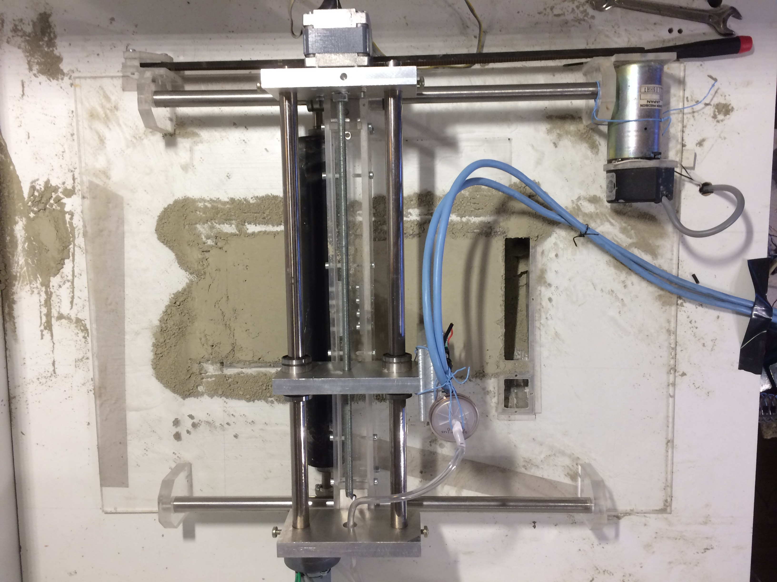
This part isn't really anything special. It is basically Y axis mounted on an X axis. Simmilar gantries are common on CNC routers and a lot of FDM printers (makerbot and ultimaker). Even though these are realy simple systems there are few factors that should be taken seriously. First one being that X axis should have drive pulleys or screws on both sides. This prevents wiggle, which gets even more noticeable when the X axis guides are further apart. This is one thing I have to make/improve on my device. Other factors are mostly the load that the gantry is going to be moving.
In most cases people use steppers and pulleys to move the gantry. For X axis I have used DC servo motor driven by L298 and arduino which is connected to a 500PPR quadrature encoder on the motor. Arduino is running misan's DC servo firmware. With good PID tunning i have managed to move the motor with 2000 steps per revolution. In combination with pulley I got a very fast speeds with approximaetly 0,01mm resolution. Y axis is a little bit more problematic as it uses stepper motor and a M6 screw, thus being very slow. Motor is also being underpowered which makes it even slower. This is why I am exchanging stepper and the screw rod with system simmilar to one used on the X axis.
"PISTONS"
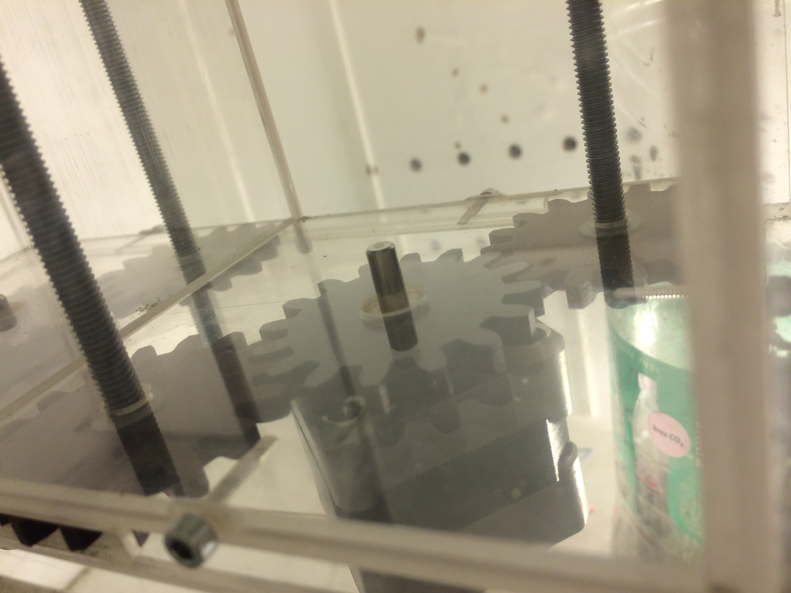
Two pistons have been made out of plexiglass. They are basically a rectangular box with divider in the middle and a double bottom. The two bottom plates hold the gears in position. There are three gears used in one cylinder. Two of them act as nuts for M6 threaded rods and one is mounted on the stepper. This one also turns the other two gears. I used the cylinder itself as a guide. This way I screwed two 5mm plates of plexiglas that fit in the cylinder. One of them is attached to two threaded rods with hole and slot that prevent the rod from rotation. Between the plates i used felt that acts like a seal and a spring that holds the piston in place.
I used two NEMA 17 stepper motors. This unit does not need to be fast but it needs quite a lot of torque. This is why the steppers were ideal solution. If I were to build a bigger piston I would have to use bigger motors.
-
Materials research vol. 1
04/27/2017 at 16:12 • 0 commentsOne of the things that has a lot of impact on print quality is material, that one is using. This is why it is very important to put a lot of mind and effort in creation of material.
Desired parameters
3DP printers use powders, that solidify in presence of some specific liquid. First thing i have decided upon is what liquid to use to cure powder. I have decided on using distilled water. I have also made a decision that liquid can have some isopropyl alcochol or ethanol in it, so i could use thermal printheads as well. I also had to decide on how my desired material should be while and after printing. This way my material would have to equally absorb water, but at the same time water shouldnt spread too much. After the print the material should be hard enough so it can withstand cleaning process and handling. This means that my desired material wouldn't be hard enough for most applications, but this is still ok as it should be sintered in the end. With all of this in mind, I have set off to create the needed powders.
Plain hydroxyapatite
First I have tested plain hydroxyapatite. It was not reliably absorbing water. After drying it just fell apart. I have also tried sintering it on 1300°C for 10h of rising temperature 2h of constant temperature and 12h of slow cooling. The results showed, that strength of sintered object depends mostly on pressure with which it was compresed before printing.
Hydroxyapatite and aditives
Based on results of using plain hydroxyapatite I thought of using aditives. I have selected tested three and am planning on trying to use one aditive more (PVA plastic) and one method (ligand transition). The aditives i have done some testing with are methyl cellulose, portland cement and dodecyl benzene sulfonic acid. I used these because these work differently, but still act as binders.
Methyl cellulose is a polymer. Single molecule looks like a long strand. When it is mixed with water the strand becomes more flexible and it wraps around bigger particles (in my case hydroxyapatite). When it is dried strands become more rigid.
Portland cement is a mixture of chemicals, that have a complex chain of reactions. Products of said reactions slowly form crystals that give strength to cured cement. These crystals also form around particles. This way they trap them in some sort of cavities.
Dodecyl benzene sulfonic acid is a quite common surfactant. It is not a binder, but it alows some sort of sedimentation of powder particles. It also ataches to particles with hydrophobic tails, while hydrophylic heads have some attraction betweent them acting a some sort of a very weak binder.
Tomorrow i will be talking a bit more about electronics and mechanics. I will continue talking about materials the day after.
-
Designing the printer
04/26/2017 at 16:26 • 0 commentsEven though the printer is already operational, I will be posting project logs about how i have built the printer. Later i will be also posting full build instructions.
PRINTHEAD
Printheads give a 3DP printer its main functionality, so it is the most important part of said device. This way the printhead is the first thing to consider. I have been selecting between three options Xaar 128, HP45 with Ytec3D driver board (check out the forum), or HP c6602. I have chosen to use the Xaar 128 as it is very easy to use (users guide). But there is one problem with this printhead, it is quite expensive (about 250$). If you have the money i recommend trying it but be careful as powders that cure in presence of water and printheads don't go well together (this is why my Xaar 128 has half of its nozzles clogged). Because of this I will be replacing current printhead with HP45. This way it will be a lot easier for one to afford the construction of this printer. Also HP45 has better specs than Xaar 128.
CONTROLLERS
For now I have been using arduino mega 2560. I have almost finished replacing it for a stm32f103 maple mini (very cheap, but quite powerful). The controller is driven trough a serial communication with a personal computer running a python program. The idea is to use a beaglebone black, raspberry pi or any simmilar SBC as a replacement for a personal computer. This is why everything running a pc is written in python. The best controller would probably be something like the Snickerdoodle board as it is a Zynq device. This means it combines an ARM processor and FPGA. It would be very useful as ARM processor would do stuff like file management, ethernet connection, etc. while FPGA would physically control the printer.
ELECTRONICS
All of the electronics excluding the controller, are mostly stepper drivers, relay drivers and PSUs. I have used different methods of driving the stepper motors. One is using the ULN2803, one is using the L298 and the third one being Pololu A4988. I have also used a DC servo driven by arduino, L298 and 500ppr encoder. There is also one motor on the spreader, but this one is only for rotation of the said unit, so it is driven trough a relay. I will also have to add limit switches and other sensors.
MECHANICS
Printer could be divided in two parts. First one being two pistons to hold the powder, and second being gantry with a spreader and a printhead. Pistons are being moved by a two gears acting as nuts, that are being turned by a gear on 1,8° stepper. I used M6 threaded rods that give me exactly 1/200 mm move with a single step (shown on the picture below).
![]() Gantry is constructed as it is shown on picture below.
Gantry is constructed as it is shown on picture below.![]() I am planning on replacing the Y axis stepper with a servo driving a slide with a timing belt.
I am planning on replacing the Y axis stepper with a servo driving a slide with a timing belt.TO CONCLUDE
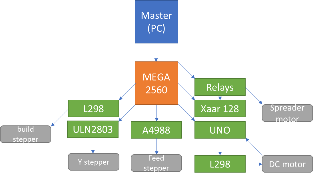
Current setup is working and uses a:
- arduino mega 2560 as a controller
- pc as a "master" to the printer
- 3 steppers and one servo
- Xaar 128 printhead
Scheme of a current system:
![]()
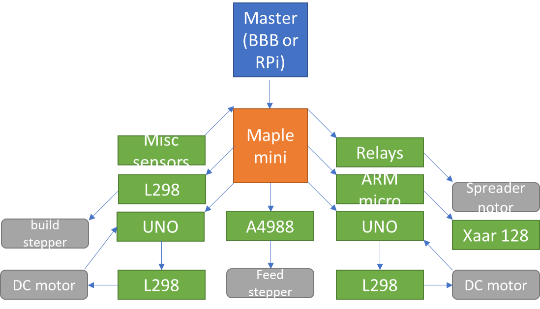
I will be trying to use a :
- ARM microcontroller or ideally FPGA (for now maple mini)
- Beaglebone black or raspberry pi as a "master" for a printer
- 2 steppers (for pistons) and 2 servos (for gantry)
- HP45 printhead controlled by a separate ARM controler
Scheme of a planned system:
![]()
Tomorrow I will be talking a bit on how to make a material. If you have any sort of questions don't hesitate just ask me.
-
Starting point
04/25/2017 at 12:14 • 0 commentsAs of writing this log entry I have already constructed the printer. I will be sharing most of the construction details. I would strongly advise anyone to use their own mind when constructing the printer. The same goes for the software and firmware. All of the parts are designed so they can be made with milling. All of the necesary files will be added later, because i have to redraw them.
Printing bones on a DIY powder bed 3d printer
This project focuses on using building a budget powder bed 3d printer capable of printing bones, and creating the needed ink and powder.