-
Gathering Information
10/02/2014 at 17:17 • 0 commentsThis log will be used to maintain what to look into that would work for different components of the Claw Machine:
WIFI connection:
http://hackaday.com/2014/10/02/gcc-for-the-esp8266-wifi-module/
NRF24L01, RFM12, RFM69
-
PIC Modifications Implemented
09/30/2014 at 02:19 • 0 comments
The following has been implemented:Allowed for communication with Claw machine mode via RS232 using the following menu structure:
prog
Enter into programming mode. Game play will be suspended after push button routine is finished (normal claw machine mode) or the button is released in test mode.
Response: ">"spdx
Change speed of X axis. Can range from 1 - 255.
Response: "ENTER: "
User Response: <enter value from 1-255>
Response: "DONE" value was set
Response: "FAIL" value was discardedspdy
Change speed of Y axis. Can range from 1 - 255.
Response: "ENTER: "
User Response: <enter value from 1-255>
Response: "DONE" value was set
Response: "FAIL" value was discardedspdz
Change speed of Z axis. Can range from 1 - 255.
Response: "ENTER: "
User Response: <enter value from 1-255>
Response: "DONE" value was set
Response: "FAIL" value was discardedtest
Switch claw machine into test mode. In this mode, the push button acts as a "shift" key. Press and holding the button with the following inputs wil respond with the corresponding action:
Forward: Lower Claw
Back: Raise Claw
Left: Open Claw
Right: Close Claw
Response: "DONE" setting was accepted
Response: "FAIL" setting was discardedclaw
Switch claw machine into claw mode. In this mode, the claw machine will play normally.
Response: "DONE" setting was accepted
Response: "FAIL" setting was discardedexit
Exit out of menu and resume play.This menu structure can be seen below:
![]()
The following will need to be implemented yet:
Save settings to EEPROM and pull settings from EEPROM on startup.
Add PWM for Claw closing
Allow serial data from RS232 port to control claw machine in normal operation
Be able to send messages to Matrix display (may not do this one due to computer tieing up port)
Use App to control device (will need to setup the framwork for this)
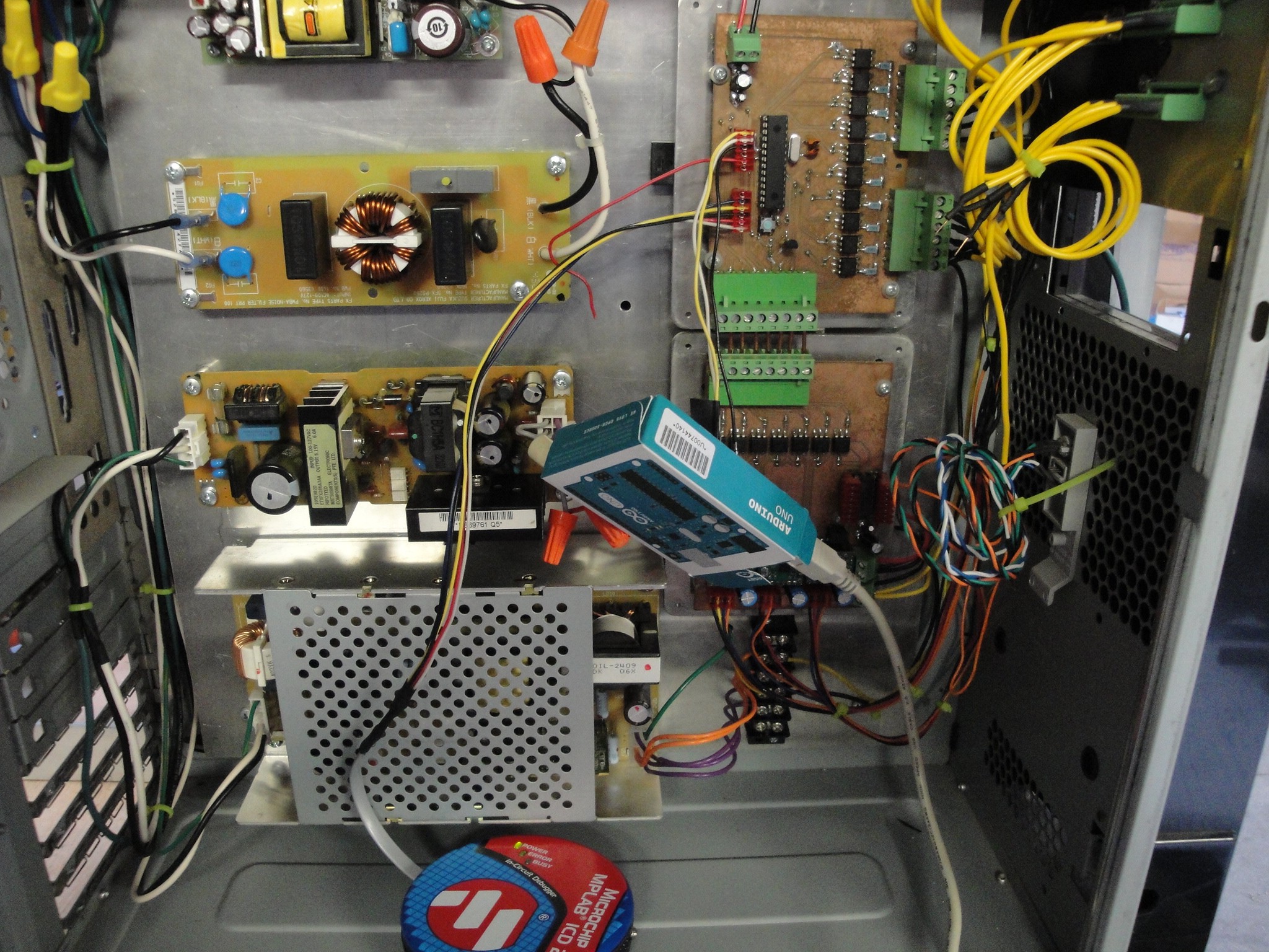
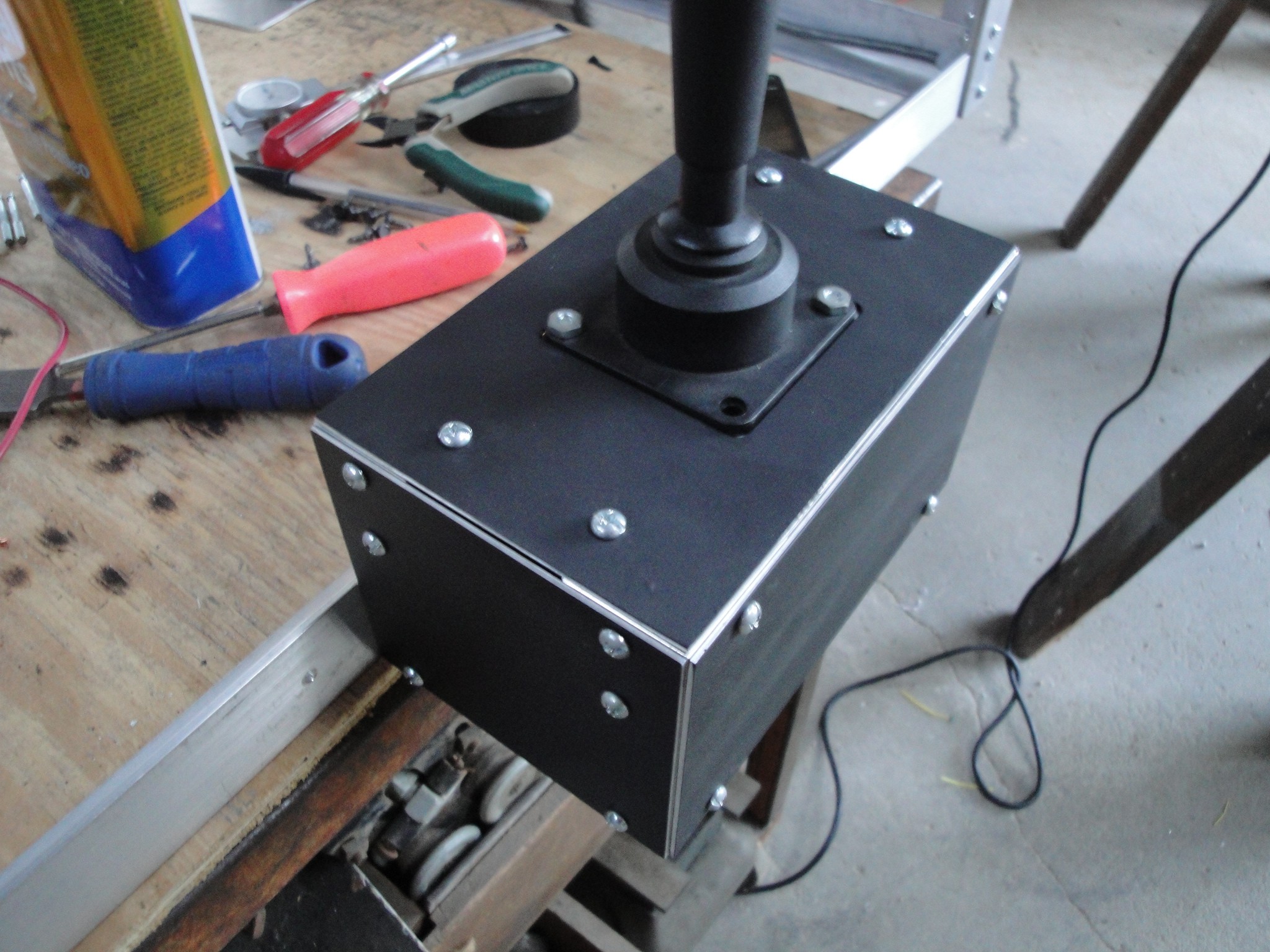
A TTL to RS232 converter has been ordered and not delevered yet. For the time being I used an UNO using the softwareserial function to allow for the UNO to act as the converter. To program the PIC, I am using an older ICD2 and v7.6 MPLABs. Here is a picture inside of the controller box with the attached items:
![]()
-
Program Modifications v1.04
09/18/2014 at 10:57 • 0 commentsTo aide in testing of different setups/toys and claws themselves, the following features would be nice to have in the program:
1. Use pwm to start off closing of claw slowly and go to full current after a predetermined amount of time. (Fade the current in on claw closing.) I did not use the right pin for the claw to allow for the PIC's pwm module. So, the pwm will have to be created in the program. This is not a terribly big deal due to an interrupt timer already in place to keep track of step pulses.
2. Allow for communications with the claw machine. Probably RS232 at this point. Be able to adjust the following via commands:
A. Switch the machine between "test" mode and "claw machine" mode.
I. Test mode - When the red button on the joystick is pushed and held, the forward, back, left, and right motions of the joystick now become raise claw, lower claw, open claw, and close claw, respectively. Otherwise, the joystick will function normally moving the claw in the x and y axis.
II. Claw Machine mode - allow for the machine to be played normally using the settings that have been saved
B. Be able to adjust the time to full claw closing in the pwm section.
C. Adjust the speed of the x, y and z axis step pulses.
D. Adjust the distance the z axis will drop when in claw machine mode.
E. Save settings to EEPROM.
The above is a start of what needs to be done first. Below are some wants for the future:
1. Be able to communicate with the Matrix Display to display different messages.
2. Create hardware to allow for a mobile phone to connect to the machine. Use app to control claw machine and adjust settings.
This is a start to the next revision of the claw machine code. I will work on this as time allows.
-
Omaha Mini Maker Faire
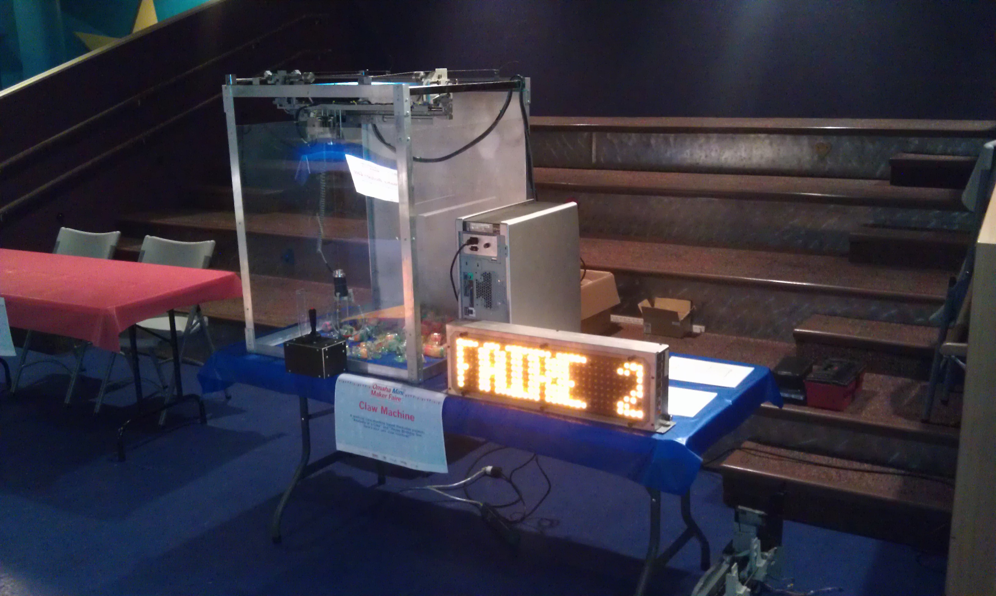
09/15/2014 at 00:07 • 0 commentsHere is claw machine at the booth of the Omaha Mini Maker Faire. It was a good show and there were lots of kids to win the prizes inside. By the end of the day, I only had to pull out a dozen of toys to just give away. Along with the exhaustion of toys, the machine ran without any random glitches. So it appears the time and effort I put into the driver board, control board and layout inside of the control box was worth it. I am pleased with the outcome. . . (plasma table tryouts?)
![]()
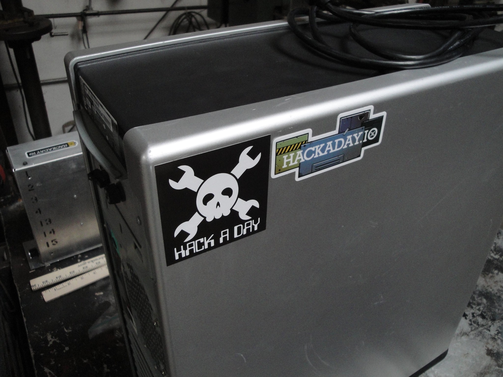
Thanks to Kristina Panos, I got some HackaDay stickers. I was not able to attach them until I got home, but they scored a spot on the side of the control box.
![]()
The only downfall to the faire was not enough time to talk more to the other makers or get their contact information.
-
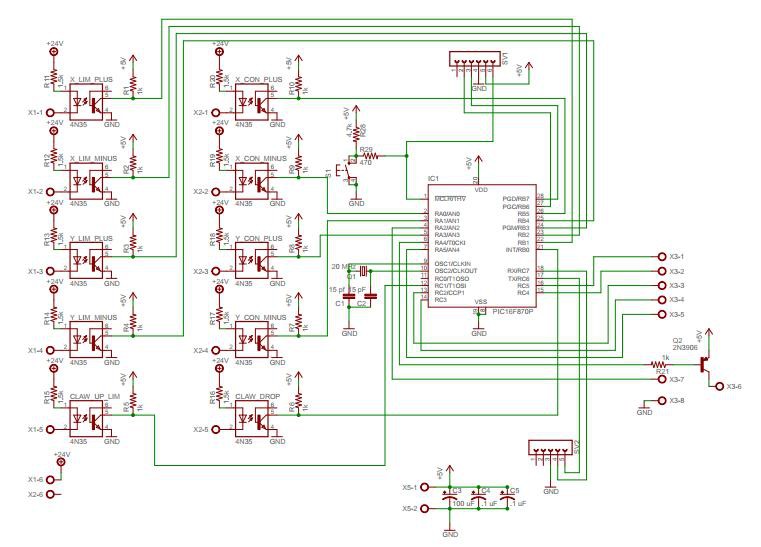
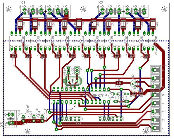
Board Design
09/12/2014 at 02:46 • 0 commentsFinally getting to posting the schematic and the board layouts. Here is the microcontroller board that controls the claw machine (schematic):
![]()
And the finished board layout:
![]()
All the inputs from the outside world (joystick control and limits) pass through optocouplers. The resistors selected was 1.5K to allow for 24V DC to be used. The bottom side of the board under the microcontroller was setup as a ground plane while the top side was setup as 5V control power. These planes were not passed under the input (24V) side of the board. Hopefully to reduce any noise that might appear.
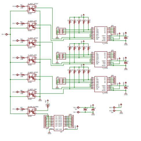
Moving on to the Driver boards, here is the schematic:
![]()
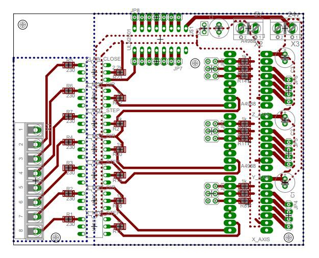
And layout:
![]()
This board was setup to have its inputs also optoisolated. Instead of 24V input voltage, they are setup for 5V input voltage. The reason for isolating the inputs, is so I can use these driver boards in other projects. If I wanted an arduino or parallel port to control them, then I just have to connect up wires and know that they will be isolated. The Drivers themselves require a 5V control and <30V power input. The grounds of these are bonded together and also passed to the bottom side of the board to act as a ground plane. The + supply voltage was then sent to the needed pins without acting as an upper ground plane. Both sides of the optocouplers have isolated planes.
-
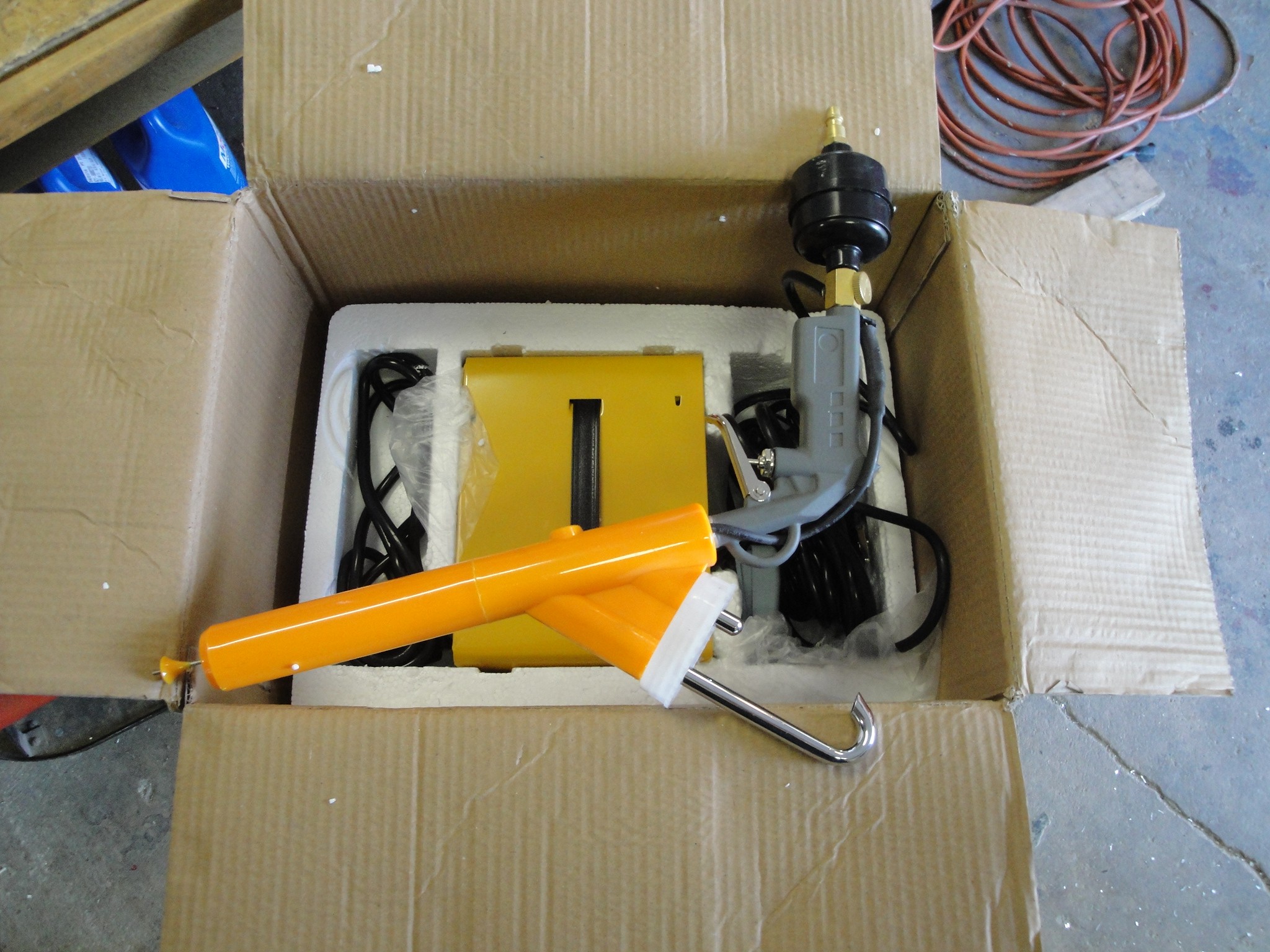
Powder Coating Controller
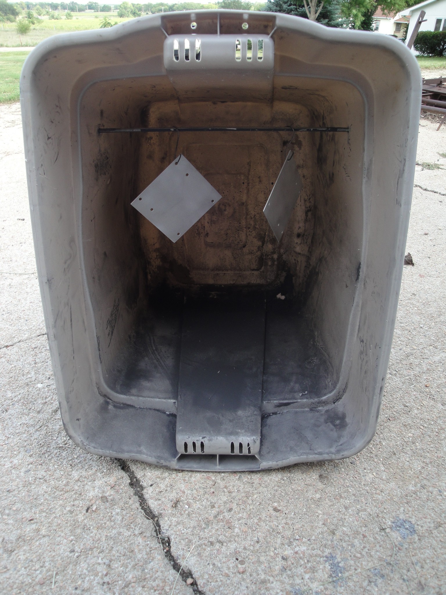
09/02/2014 at 00:38 • 0 commentsIn trying to make the machine more presentable, the joystick cover plates will be powder coated black. The Harbor Freight powder coat gun was used. This was used on the Claw solenoid housing in the past. It came out looking nice, so I figured I would use it for the joystick also. Here is the gun that was used:
![]()
The cheap tote powder coat room:
![]()
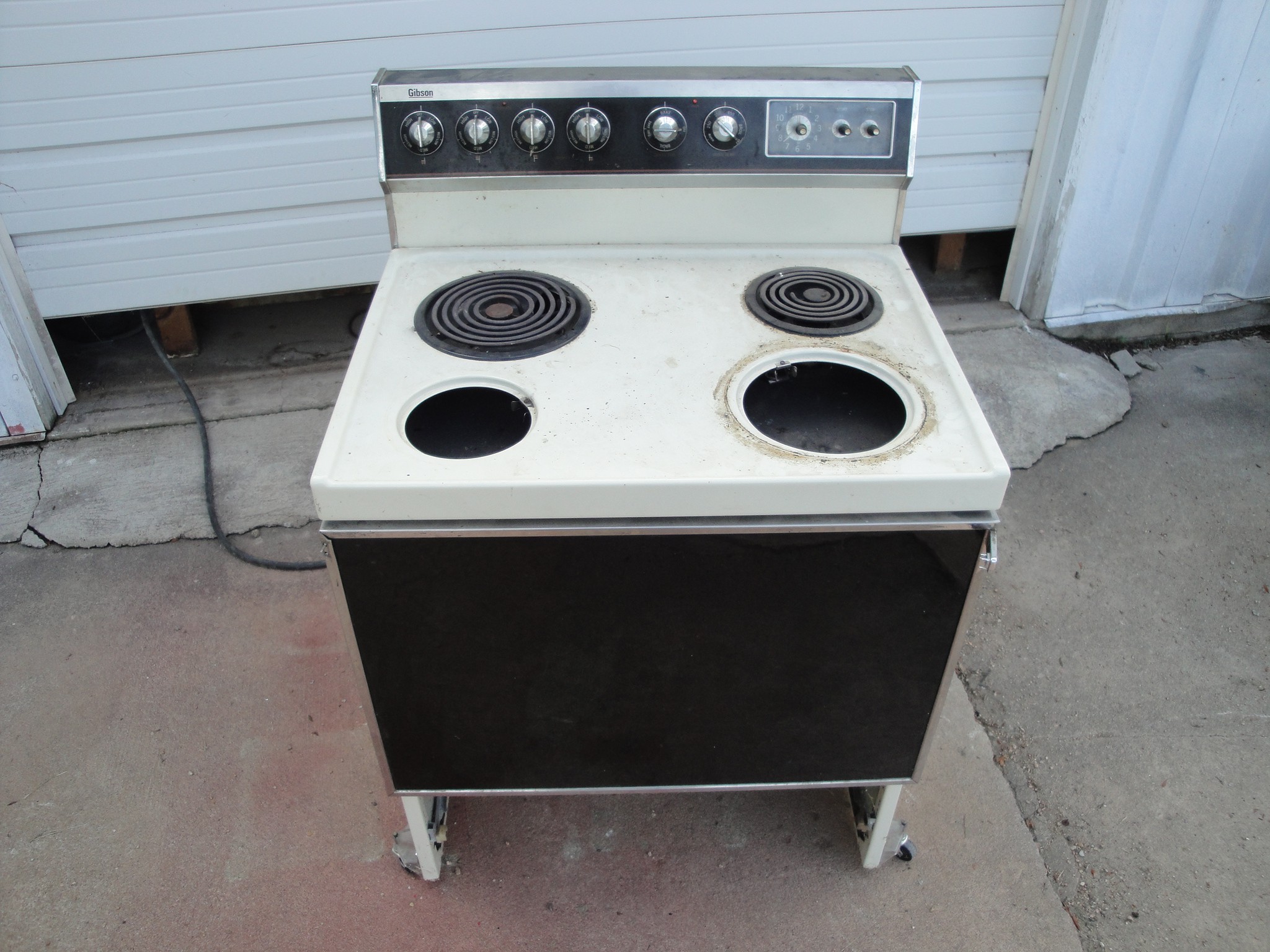
And oven with wheels to moved it around:
![]()
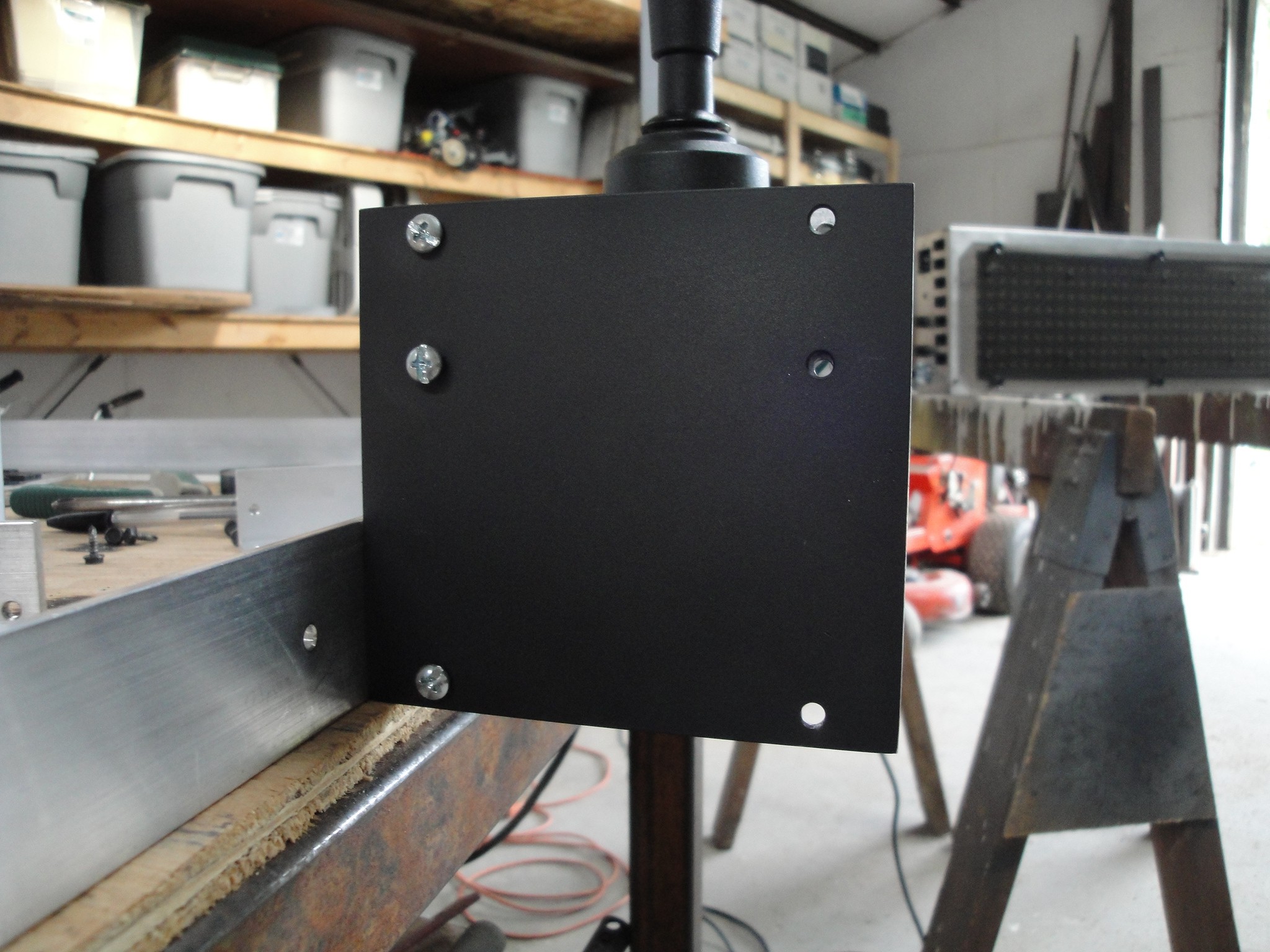
Here is the finished product waiting for other panels to be mounted along side:
![]()
![]()
This is a pretty easy process, but this time I had a problem with clumpy powder coating, not enough coverage giving it a dry look and not completely covering the edges. Here is a breakdown of what I did:
Clumps - Wiped off the part, cleaned the surface again with alcohol and reshot the part with powder. Then placed it in the oven.
Not enough coverage - After seeing the part after it had been in the oven, I reshot some more powder coat on the part after it was cool. After the second round of heat, the part appears to look better. We will see how this affects long term abuse.
Edges not covered - Instead of reshooting the edges, I just took a file to them. This stripped the edges of powder coating and added a detailed sharp edge. Once the other parts are done, it should make the edges stand out and give a good look.
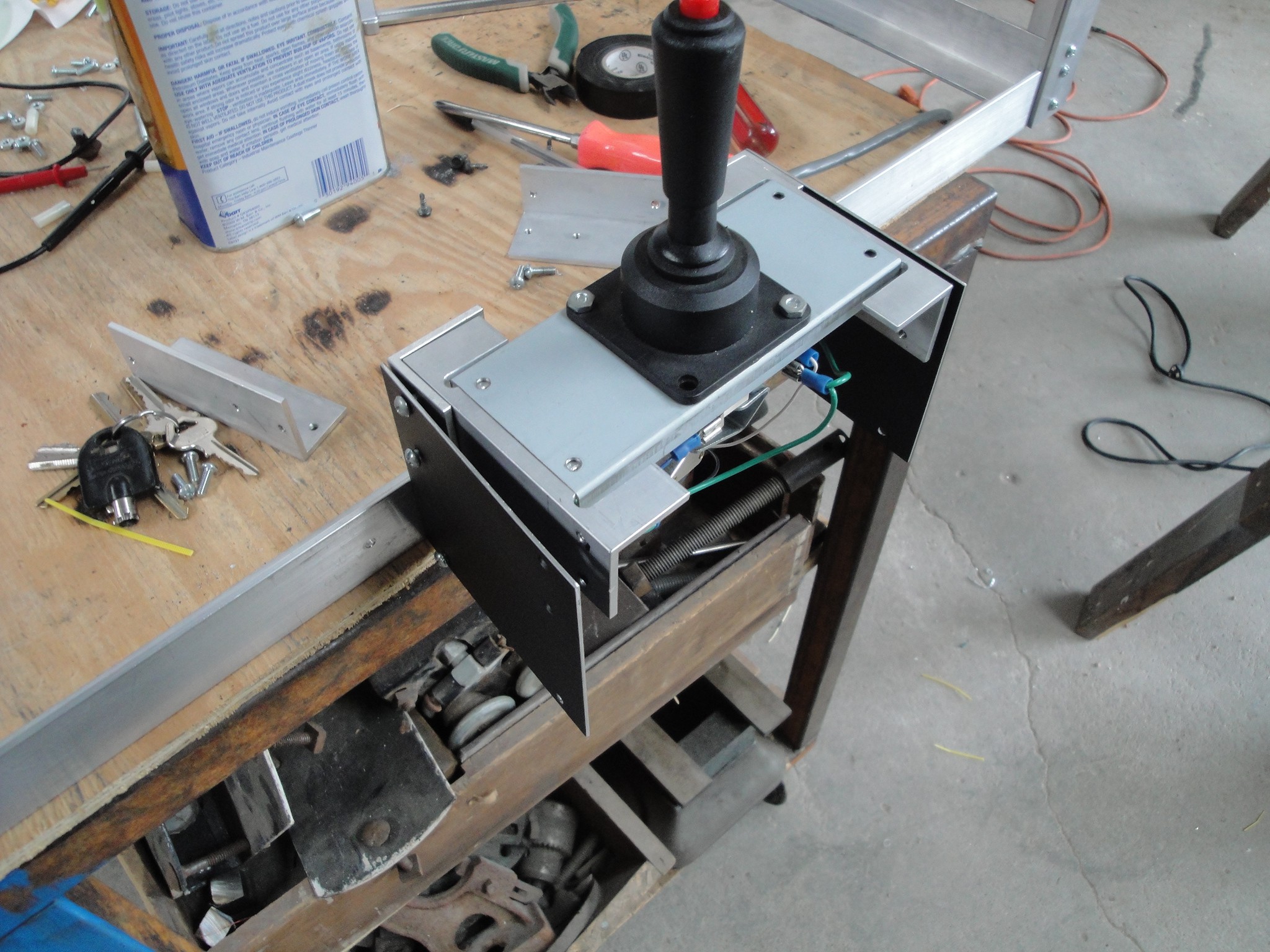
Here is the finished product:
![]()
The top and front larger panels were the ones that were shot twice. The one drawback is it caused the panels to have a rough or dry feeling to them instead of a smooth surface.
All that is left with the claw machine is re installing the plexi glass and cleaning up parts of the machine.
-
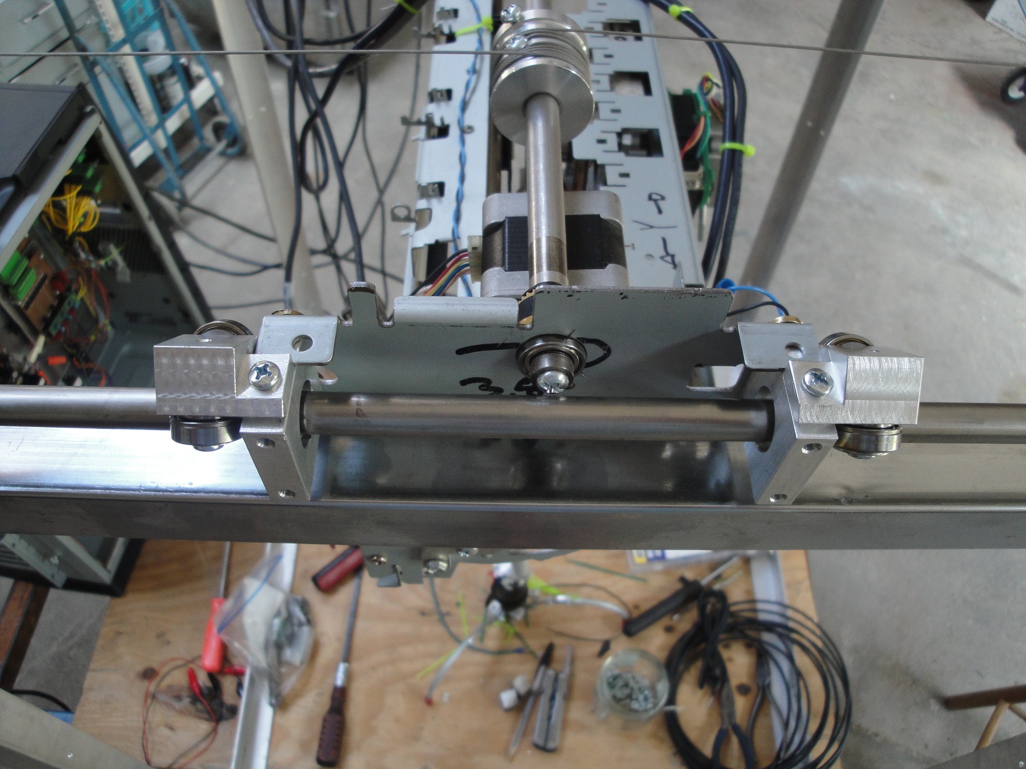
Y Axis Bearing Change
08/30/2014 at 22:45 • 0 commentsUp until now the Y axis has had a plastic bushing that needed constant maintaining by adding grease or increasing the amperage on the stepper drive. They have been removed and now there are ball bearings installed. Here is an overall view of the change:
![]()
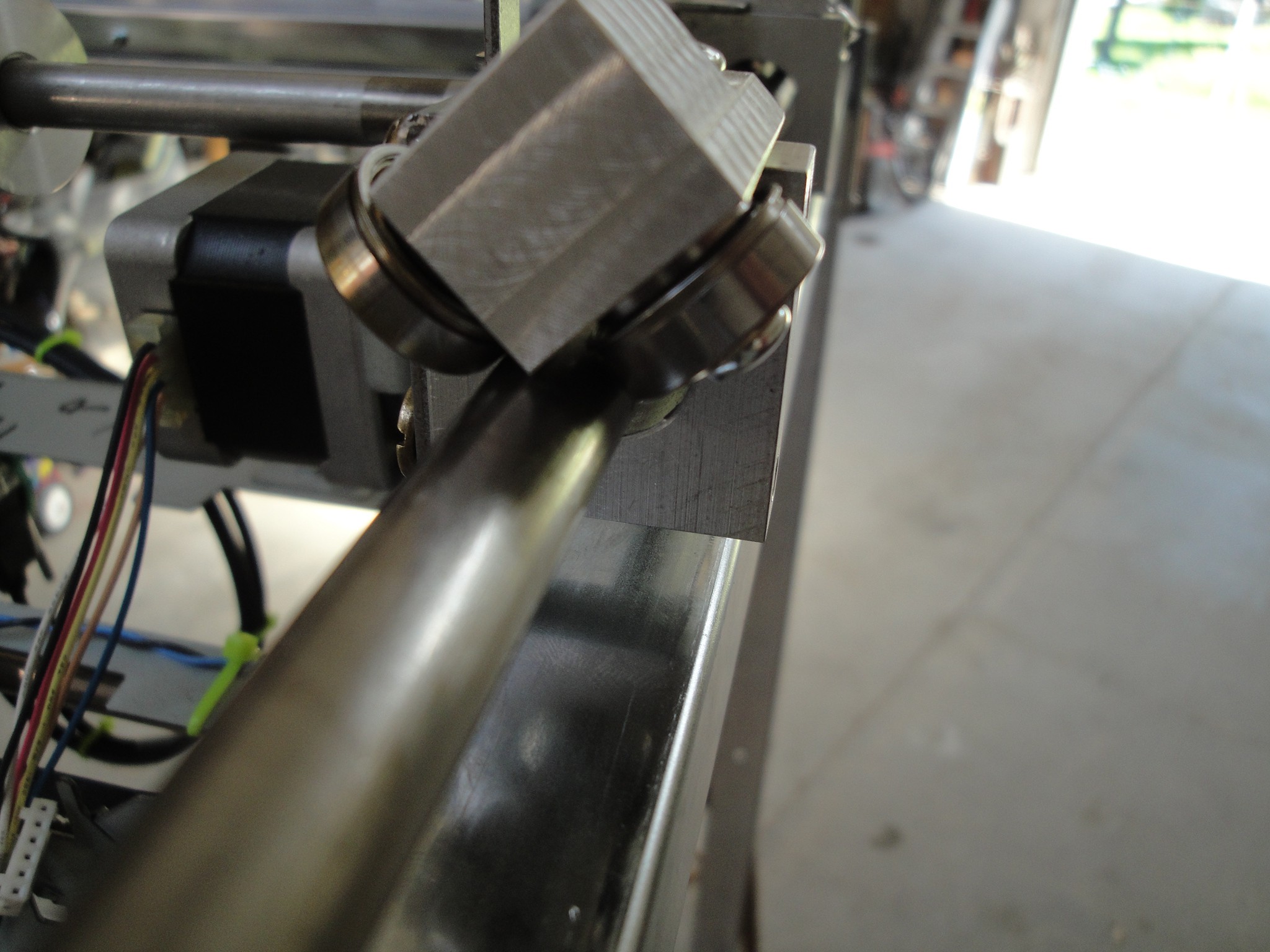
Closeup of the left:
![]()
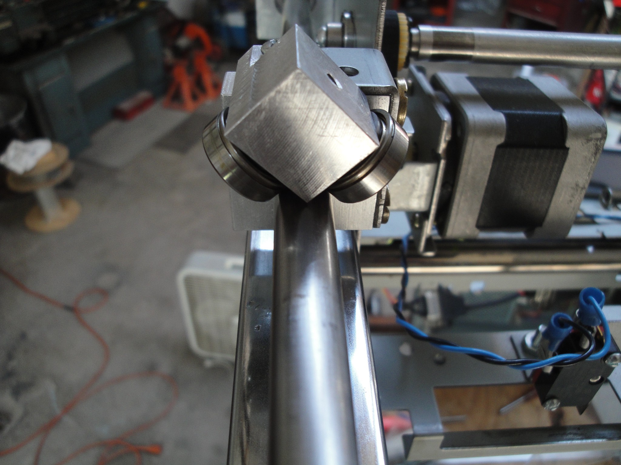
And the Right:
![]()
I opted to not have a bearing on the bottom of the carriage as a little play in the Z axis will not affect the game. To keep the carriage from completely jumping off of the shaft, the bushing blocks with the plastic bushings removed, were left in place.
This update smoothed up the travel and was worth the time to build.
-
Wired Test
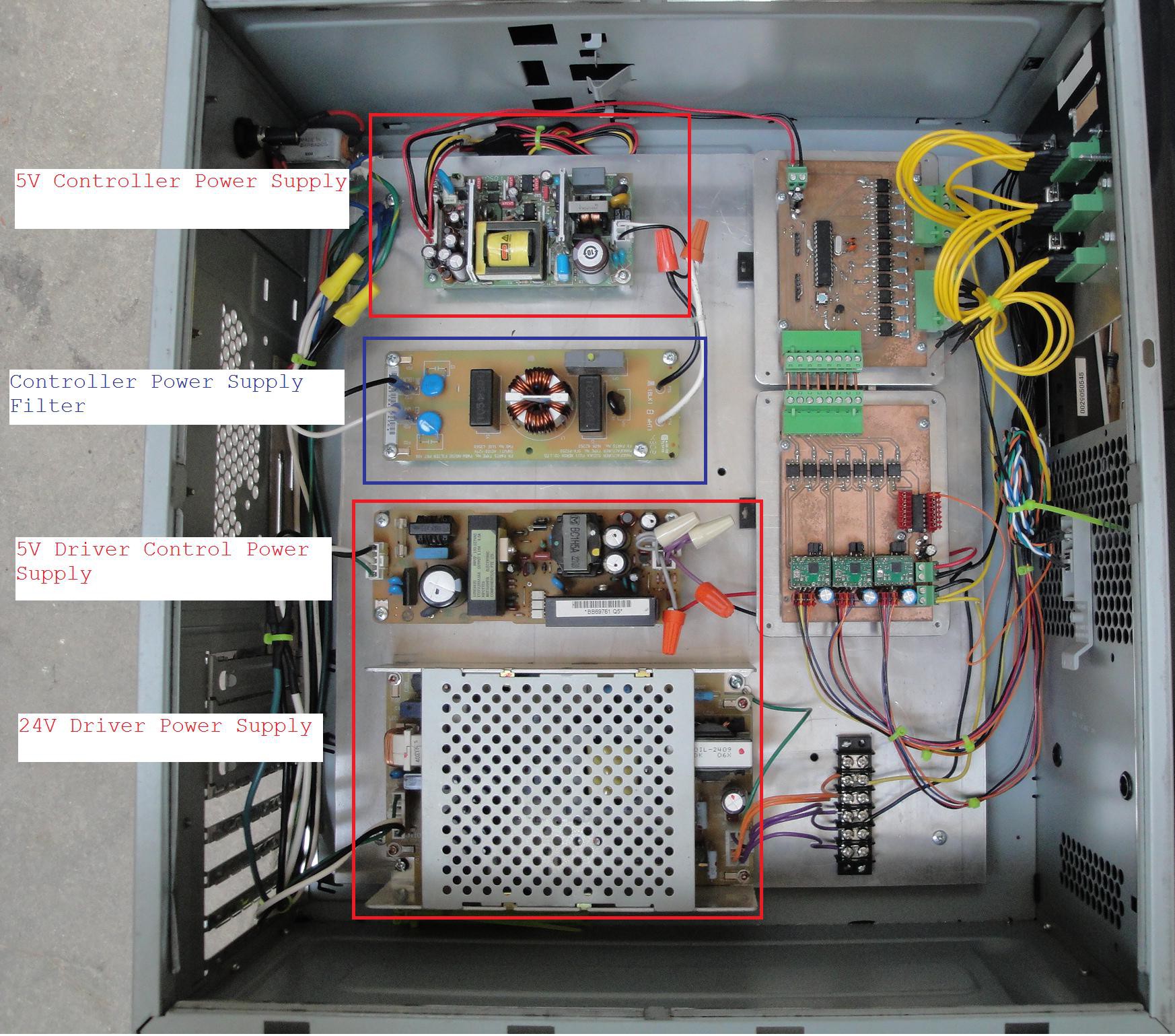
08/25/2014 at 03:03 • 0 commentsNow that the boards were complete, the boards could be wired into the box. The boards were designed to keep the 5V power supply voltages separate between the two boards. This required 2 separate 5V power supplies to feed the control voltages to the controller and driver board.
Below is a picture of the layout. The upper left hand corner board is the controller power supply. This is fed by filtered 120V line voltage.
Bottom left is the 5V and 24V power that is used on the driver board.
![]()
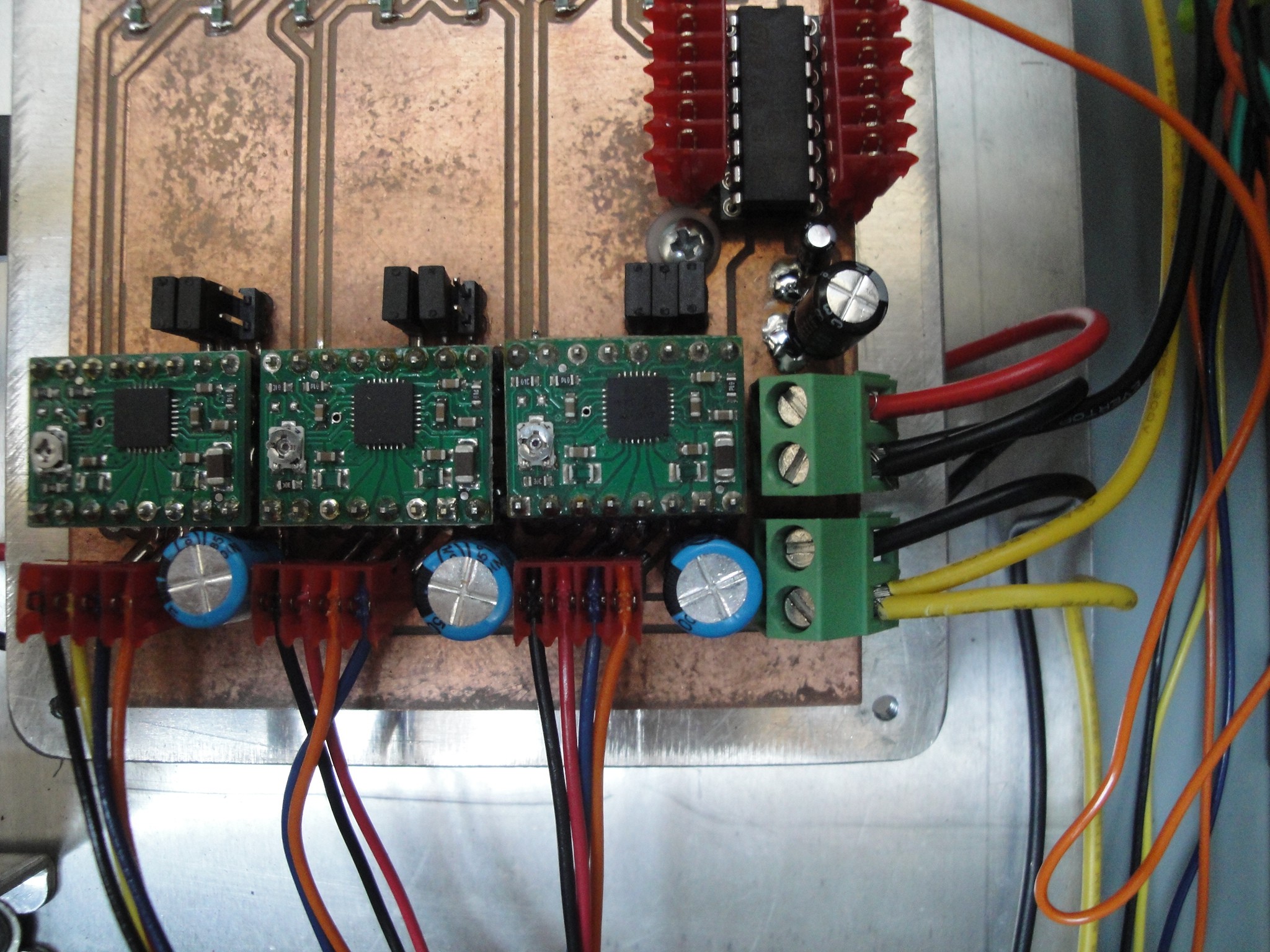
Next up was wiring the limits and joystick for minimal operation. I jumpered the Z positive limit and powered up the box. This led to the first problem. The motors were not powering up. Eventually diagnosing led to the 5V driver board power connector.
The two connectors to the right of the board is the 5V (upper green connector) and 24V (lower green connector) power supply inputs. The 5V supply power pin was not adequately soldered down. This was fixed by a quick solder.
![]()
The motors now powered up, y axis would home, but the x axis would not move. This was due to the program being changed to allow for easier creation of the boards. Once the program on the micro was updated to the correct version, the machine would now home in the x and y axis.
Currently the machine has the claw re installed and operational, the wiring run haphazardly and needing to be fastened, and the joystick not mounted to the machine. As far as I can tell the boards function correctly as all the limits work, the joystick controls the machine in the x and y axis, the claw closes when required and the machine homes correctly.
The next step is to clean up the machine and make it more presentable.
-
PCB's Done . . . but not tested. . .
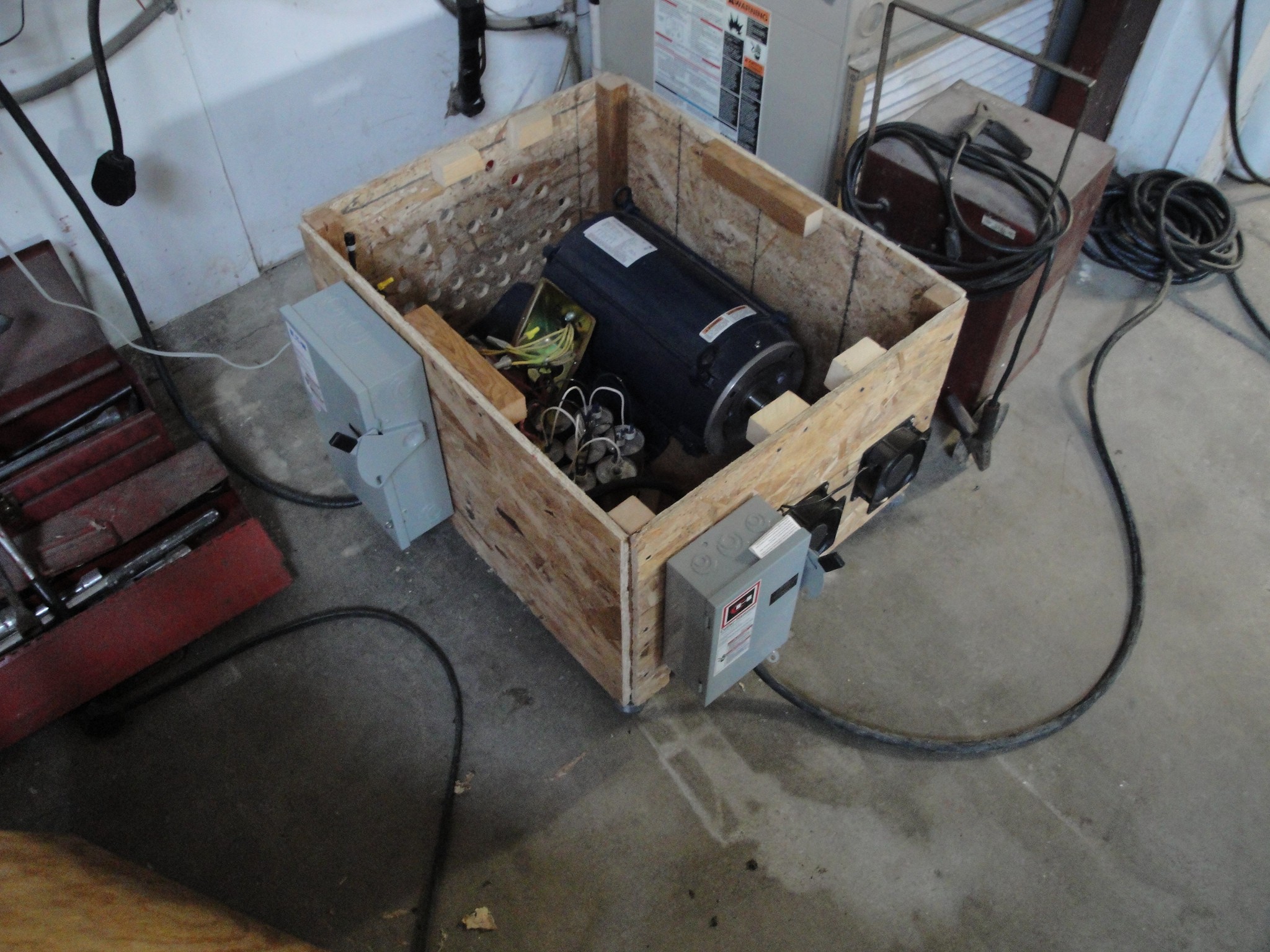
08/16/2014 at 02:26 • 0 commentsThe boards are finally finished. This was a long time coming, but I could machine the pcb's (which I have been wanting to do pcb milling for quite some time, but things did not fall into place until now) the mill have to become operational. The mill is a Chiron FZ08W that needed to have 3 phase hookup. The shop that I use has the 3 phase by the shop but not fed to it. Hopefully this will happen in the future, but for now, my former employer allowed me to borrow his 3 phase motor and some phase converter capacitors. Here is a picture of the box that I roughed in and placed on an old copy machine frame.
![]()
It has a single phase fused 60 Amp disconnect for the main feed in. This goes to the phase starter, capacitor bank and 3 phase 20 HP motor. From there it goes out to a 3 phase 30 amp disconnect that feeds the machine. There are two 120V fans to help with the cooling of the motor. I have plans to move them to be near the side of the motor casing since the cooling is not adequate in the position they are currently.
Once that was up and running, the boards had to be designed. I used the free version of Eagle as that is what I was taught way back when. From there I used the pcb to gcode converter. This is quite handy, but when the CNC has a limited amount of memory storage (not desktop computer, but instead a 21M FANUC controller) then the size becomes an issue. I had not setup the DNC drip feed yet which would allow for line by line feeding, so I ended up breaking up the programs into separate smaller programs.
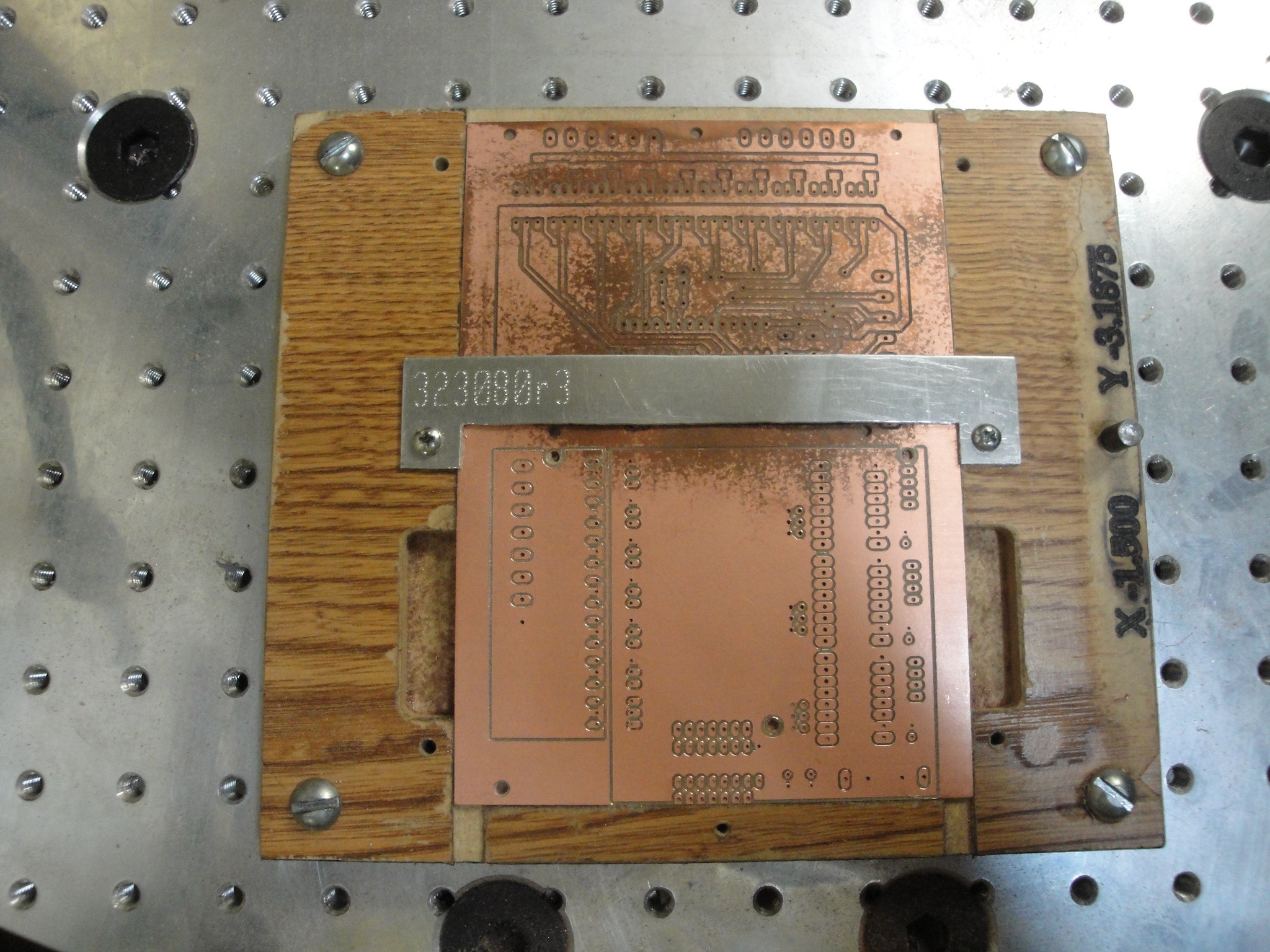
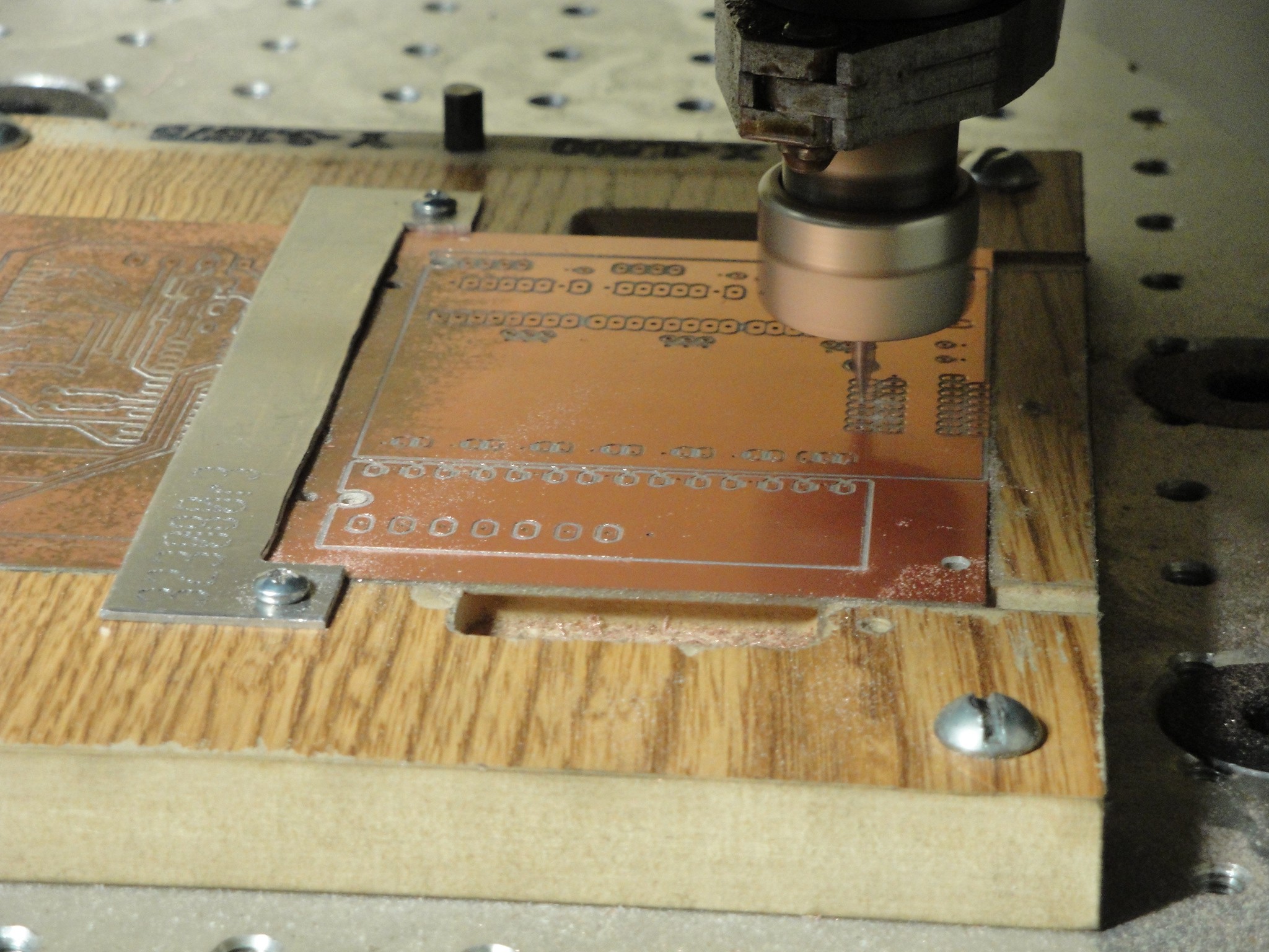
For the fixture, I used just a piece of cheap shelving board. It is quick and easy to machine and it machines without coolant. Here is a picture of a pcb after machining still sitting in the fixture.
![]()
And here is a picture of it being machined:
![]()
Now my machining skills required some dusting off along with learning a new material. The problems I ran into:
1. PCB board not flat within .002". With the pcb mounted to the fixture, it would deflect up to .010". This is not good when trying to make a nice finish. The first cut of the controller board came out poorly. The copper was pushing a pretty heavy burr. This required using a honing stone to get rid of them. To prevent pushing a burr on the next cut, I raised the z offset until it would just cut the copper and not the fiberglass? beneath. Once I finished that program I looked to see if it had cut all the way through across the board. If not, I would lower the z offset by .0015" and rerun the same program. Repeat until the traces were cut out. I found this to work and keep from pushing a burr on warped/deflected boards. Very long and tedious process. If I do this again, I will plan on using a vacuum table or double sided tape.
2. Played with speeds/feeds. I ended up with 9500 RPM and 9-10 ipm. The max spindle speed I have is 10000 but wanted to keep from using the limits. 9-10 ipm was leaving a good finish.
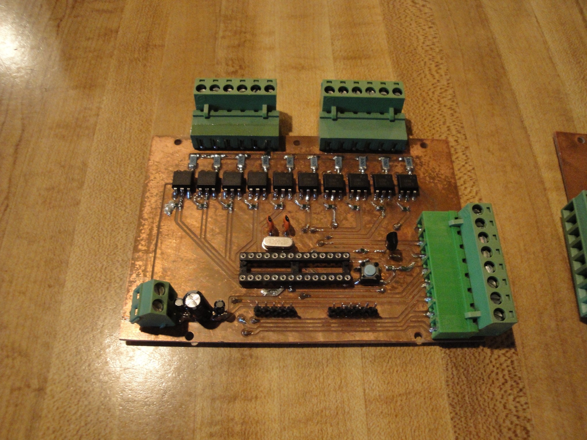
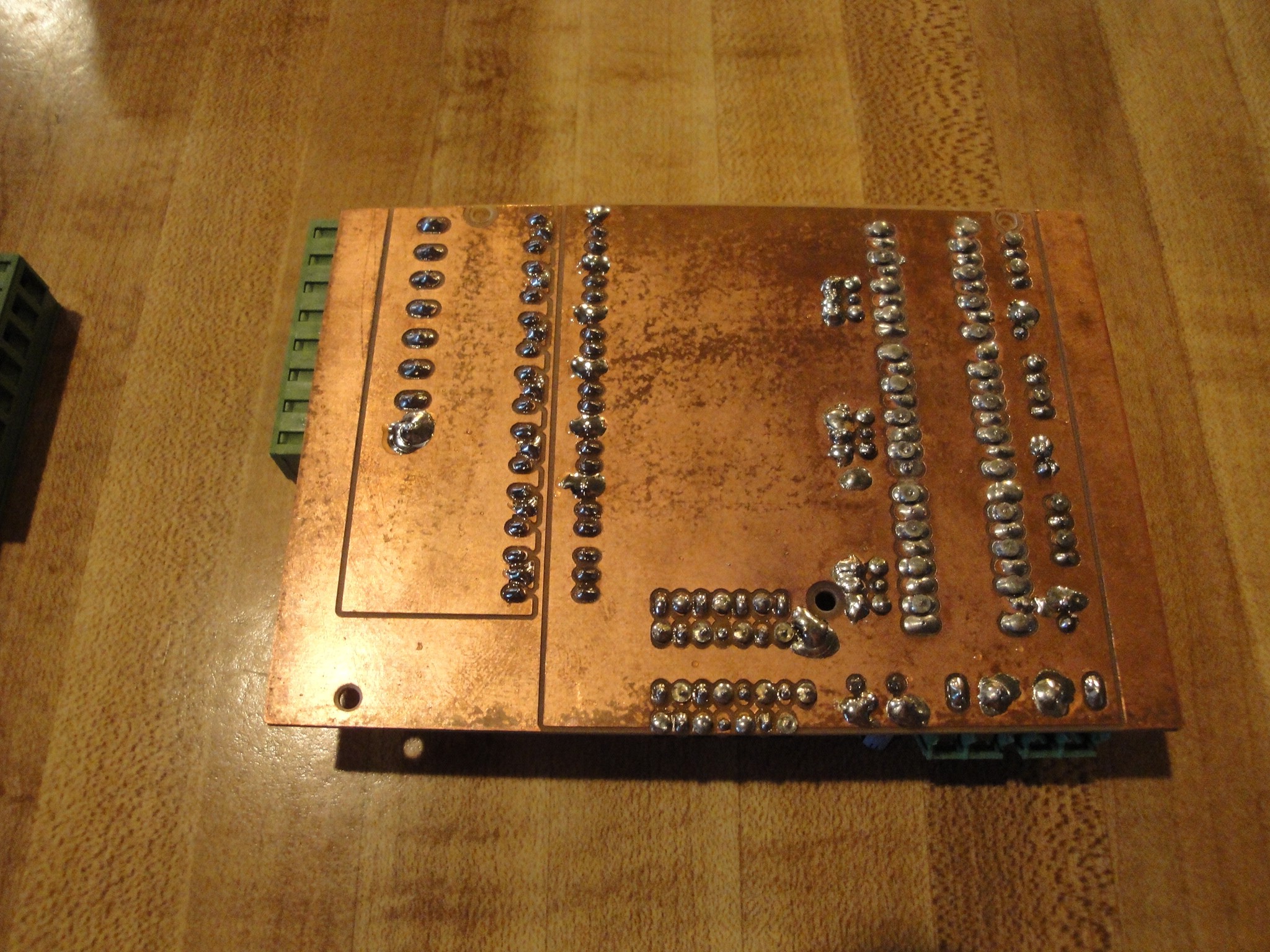
Now that the pcbs were machined, I then populated the boards. Solder jobs do not look the greatest, but continuity has tested ok. Here is the controller:
![]()
![]()
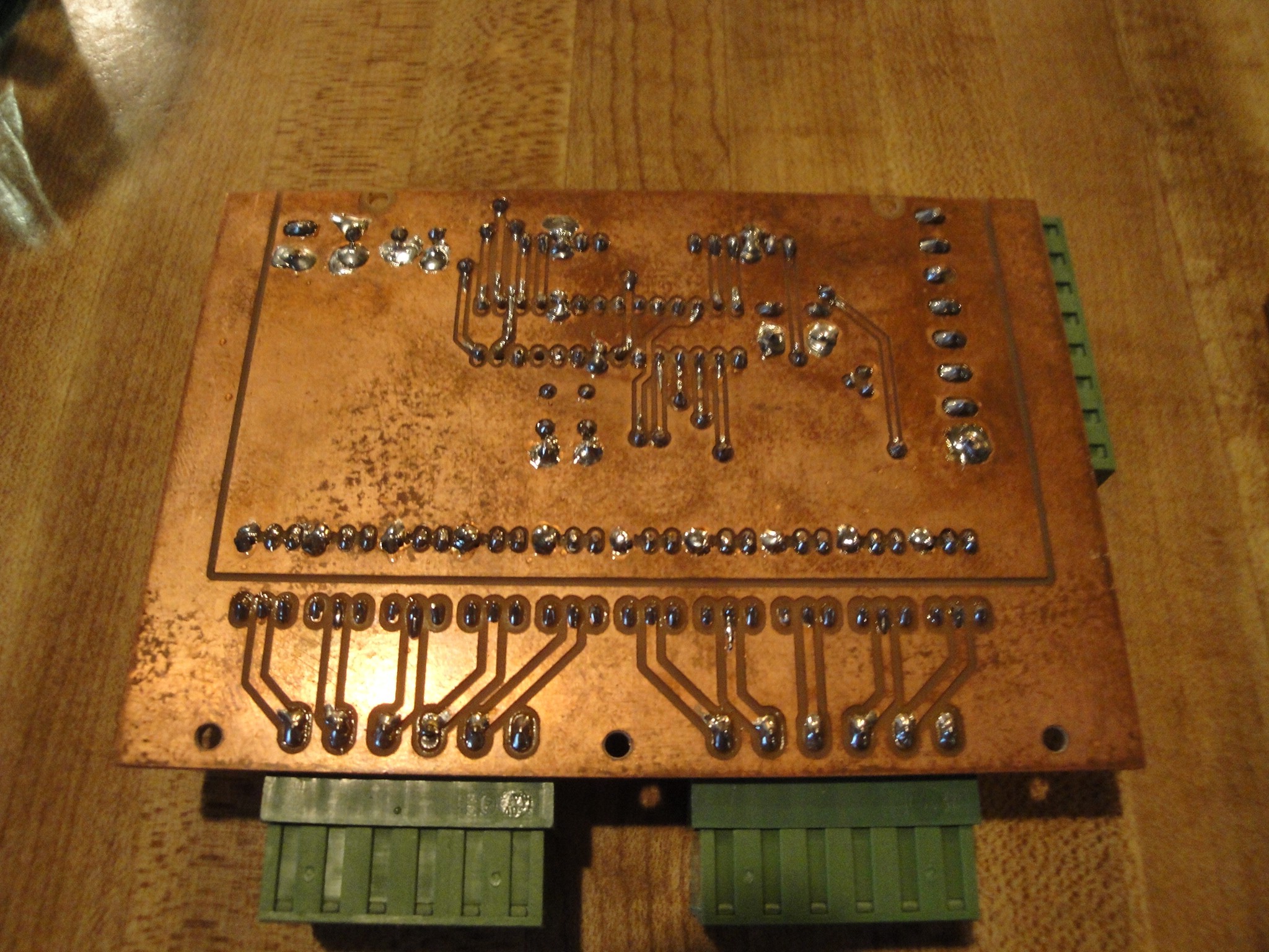
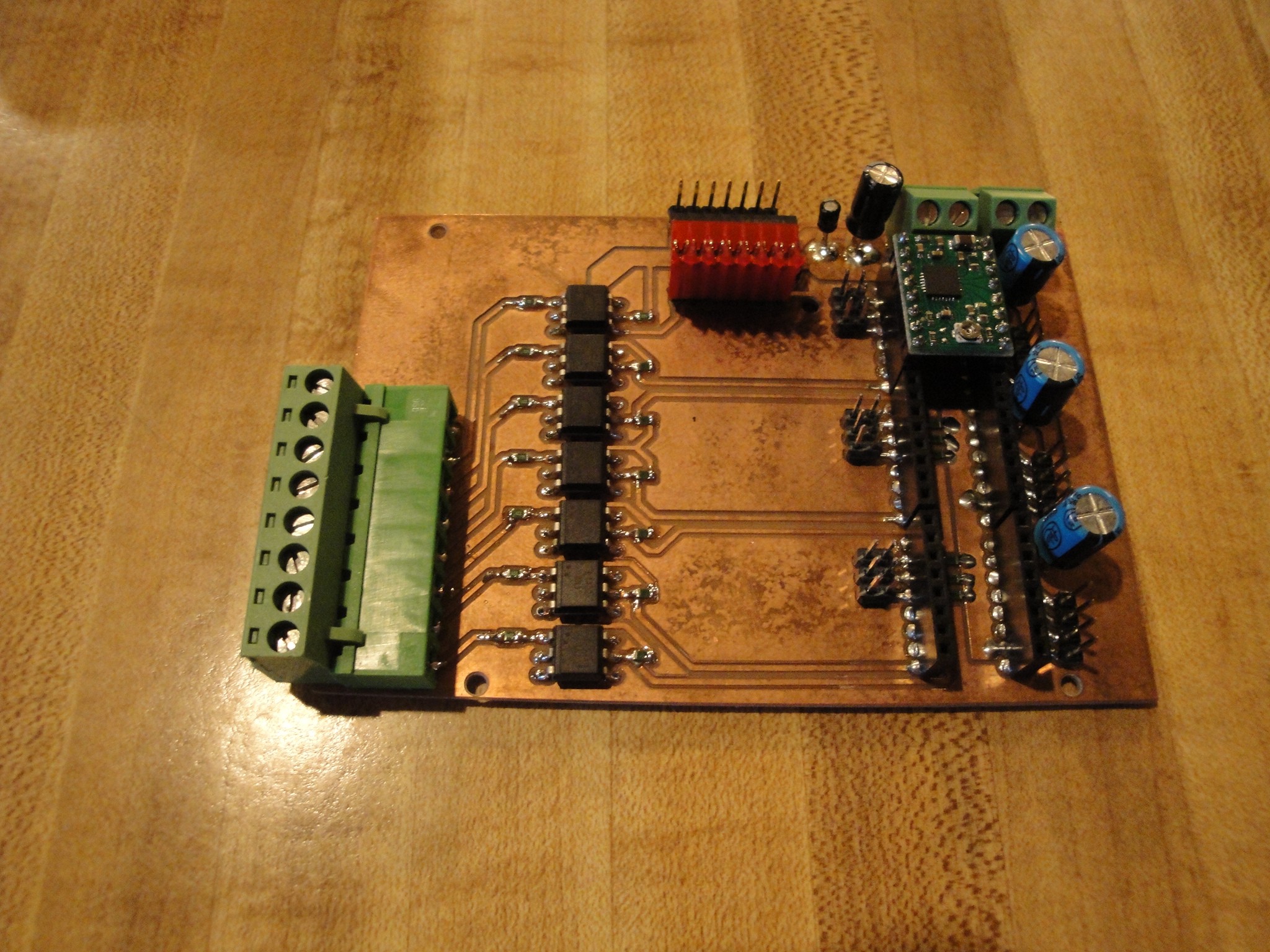
Here is the Driver board:
![]()
![]()
The next step will be to mount the boards inside of the computer case and finish wiring.
-
Noise Immunity
03/16/2014 at 22:37 • 0 commentsNow that there have been a couple events under the belt for this machine: sons birthday party and a carnival, I am looking to make the claw machine more noise immune.
The last event showed a random reset of the machine that would cause it to home out. As if the program was being told to reset or an MCLR pin had been set low. Not sure where else to look, I intend on doing the following:
1. Replace all wires running to limits and joystick with shielded cable wires.
The joystick is no longer screwed to the frame. I can move it freely like a wired remote. It has also been updated to use a shielded cable. I then checked to see if a plasma cutter will cause resets when it first fires an ark. It still did. I then proceeded to remove the z axis (claw height control) and also the limit switch for the z axis. These both were no longer being used as I removed the claw and claw drop motor for testing with a plasma cutter. Once these were removed my reset problem quit when firing the cutter. But if I would touch the plate being cut to the grounded frame (using a groudn lead from my controller box and being grounded via the outlet), then the machine would reset. This lead to looking into grounding practices on CNC plasma cutter machines. It looks like these installs include a grounding rod at the machine and grounding the machine to it. I will attempt this in the near future as there are steel tie downs in the concrete in the shop I am using.
Tried a second night of squashing noise from causing problems. Grounding to the tie downs did not seem to cure any problems. What we did notice was that when the plasma cutter was sitting on a trailer, we could not get rid of the reset issue, even if we kept the ground for the cutter away from the grounded frame. Once we placed the plasma cutter on the ground then it would work fine until I touched the work to the frame.
We also tried to throw the whole controller into a stainless steel refrigerator with all sides grounded. This still did not cure the problem. What did finally cure the problem was when all wiring was pulled from the frame and placed inside of the refrigerator. When I would connect the limits back up then the problem would reappear. If I would unhook the limits and hook the motors up, the problem will still exist. The motor frames are grounded to the frame but the cable shielding is not grounded to the frame, only at the controller. There is about 4 inches of unshielded cable right near the motors. There is also about 12 inches of unshielded cables running to the limits. The limits are also NO. This might be changed to NC to hopefully get rid of some of the noise.
2. Make a PCB for the PIC or ditch and convert to an UNO I purchased a little while ago.
The board has been designed. I am planning on milling out the pcb with a CNC mill that was purchased. This is a slow process as it is 3 phase and as time allows I have been getting a phase converter up and running that is contained. Also had to build some fixturing to raise the bed up to allow for direct bolting fixture plates. The board uses opto isolators to isolate the outside switches from the controller.
3. Find complete metal enclosure and place electronics inside.
Will still maintain the computer box as that is what I have for now.
4. Look into noise immunity between the A4988 and the controller. Look into RepRap boards to see how those are designed.
The new board designs will utilize opto isolation between them. Will also use two different 5V power sources.
5. Look into more filtering on the 110V side.
Found a filter from a copy machine and plan on installing this also.
This is as far as I can see into mitigating this problem as I do not have much experience with this. We will see where this leads. . .