-
Motor Purchased and Mount Underway
07/17/2017 at 15:43 • 2 commentsSo I pulled the trigger and purchased a brushless motor with an ESC. This one to be specific. This one "should" be able to spin at 30k with a 2S LiPo under the weight of the rotors.
So now I'm designing and printing the mounts and stands for the compressor and motor so I can run it safely.
As always, I'll try and keep y'all updated as I go along.
-
Constructed
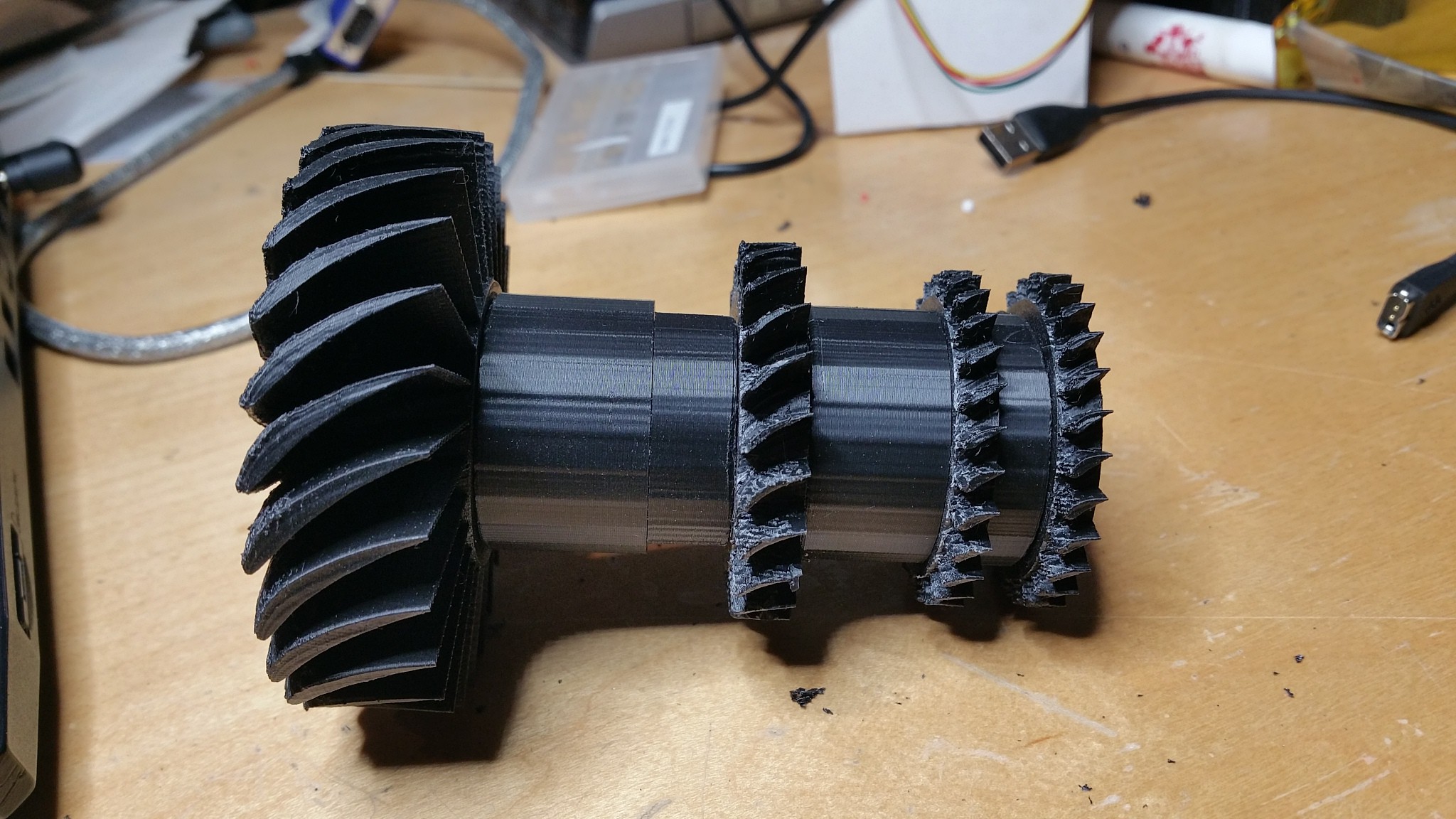
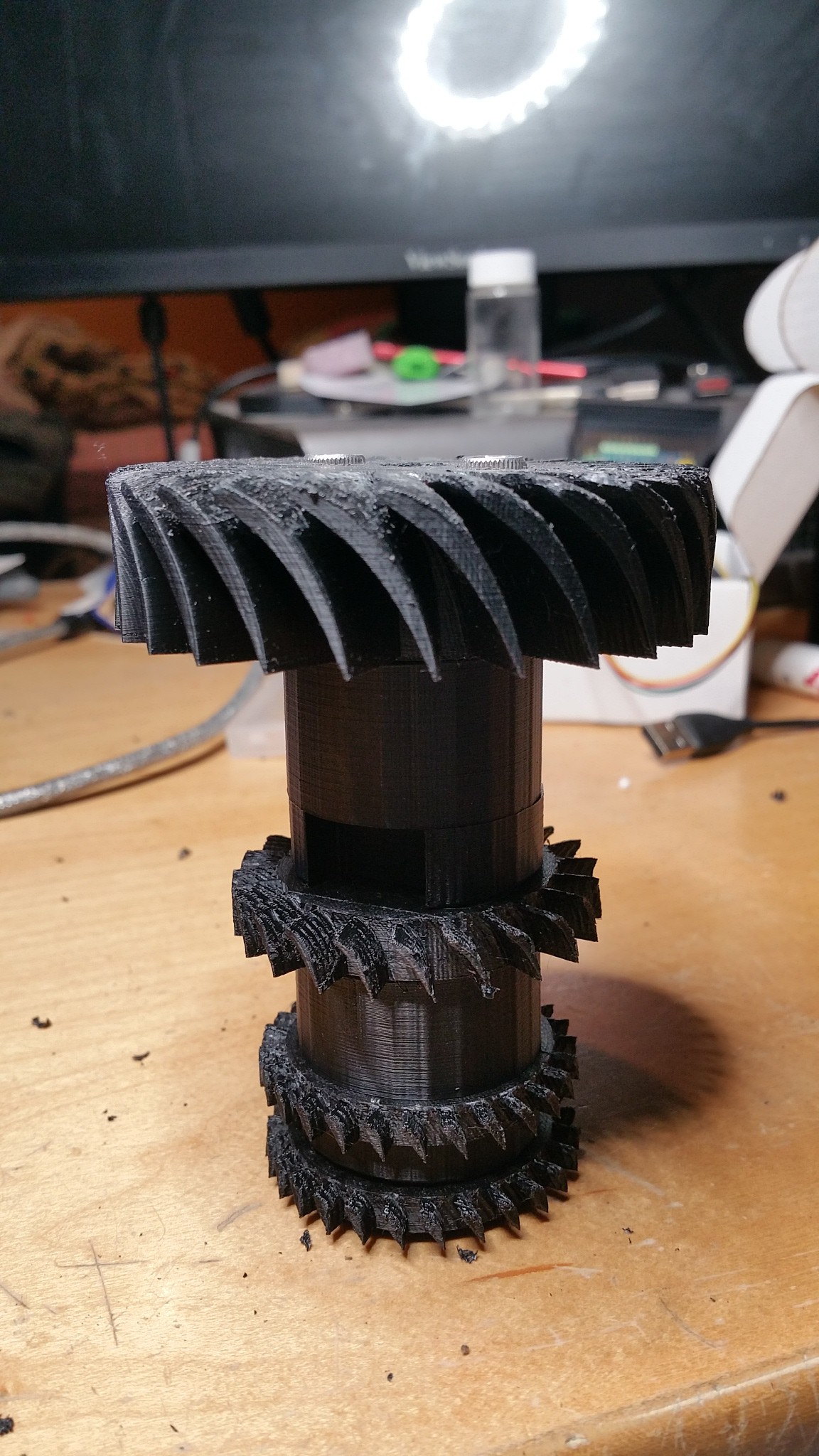
07/04/2017 at 01:07 • 0 commentsAfter a grueling couple of months and low tolerances, the prototype is finally constructed...and to my surprise everything fits perfectly, odd.
I can't really give many angles of the prototype because of how it's assembled, it took almost an hour to get it right, so I've only attached the profile picture of it. To put the size into perspective, it's about the size of a tallboy. For those non-Americans that's a 22 Oz of beer...preferably Bud.
![]()
My main concern was the possibility of my printer printing the bearing housings off center, but everything seems to be aligned, at least well enough for now.
The next thing is to buy the brushless motor and controller to power this. I'm looking at a 4100 kV motor, but if anyone has any recommendations hit me up - my expertise is not electronics.
Happy 4th.
-
New STL and Book
06/21/2017 at 22:49 • 0 commentsI've updated the .stl files with the latest version. This is the version that is being constructed. It is also the one that pictured above.
I've also been asked how someone could learn to make something like this, or just learn about turbomachinery in general. This link, is a link to the textbook that was basically my bible. With this and all of the freely available sources on the inter-webs, anyone could learn this.
Cheers!
-
TOTAL Overhaul (hopefully the last)
06/12/2017 at 16:39 • 0 commentsNow I said in the description that I was hoping that this final iteration would be the last, and I'm still considering that hope achievable even though I did a total overhaul...I'll explain.
So I was finalizing the design of the engine when I realized how impossible it would be to fabricate the clamshell-stator assembly. The whole point of this project was to be able to 3D print it and then cast it in aluminium; this way anyone can have the ability to do this. With the previous case design, that was nearly impossible.
So introducing the last 2 weeks of my life...
I didn't do any new calculations, the engine should still operate the same except now it will be able to be produced instead of being a rendering. This is also why I'm not considering this Mark 7, it's the same engine except with a different (and better) face.
I rebuilt the case to have a rail-ish system, where the stators would slide into the designated spots and then be bolted down using M3 screws. The rotor assembly wasn't touched in this rework so those still operate the same. I then added the long overdue cowling and outlet nozzle. These also were built this rail/bolt system because all of the stress will be on these two pieces because they also house the bearings.
If I'm not explaining this well enough I've got pictures.
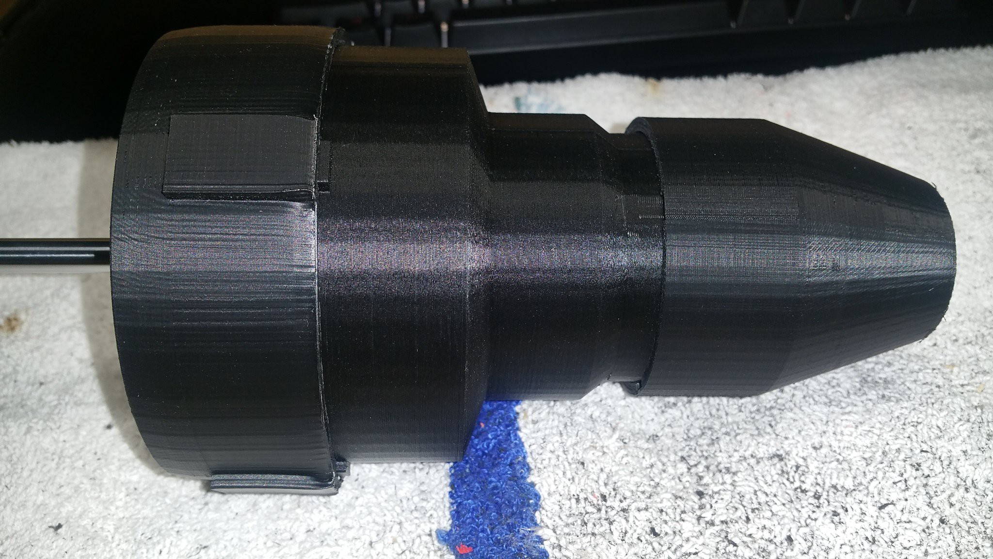
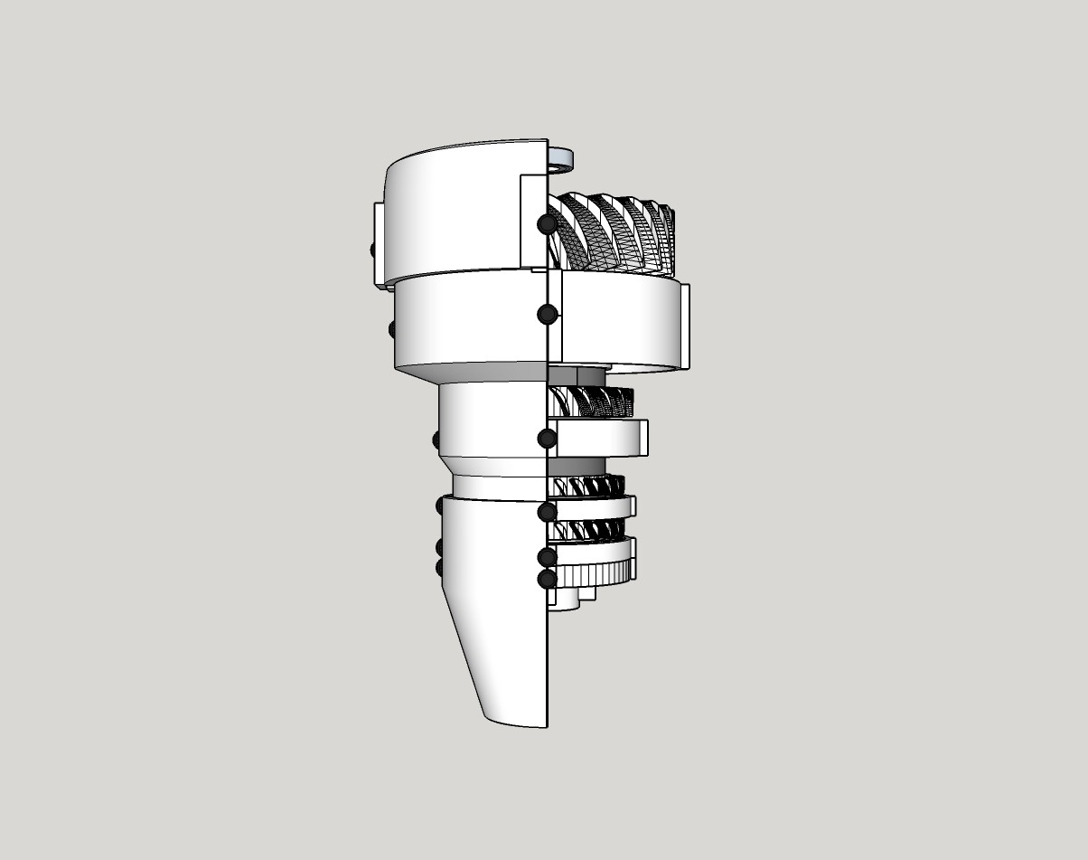
![]()
Fully assembled (minus the axle) new compressor design. Notice the exit cone vs outlet diameter, these also had to be painstakingly calculated
![]()
Side View
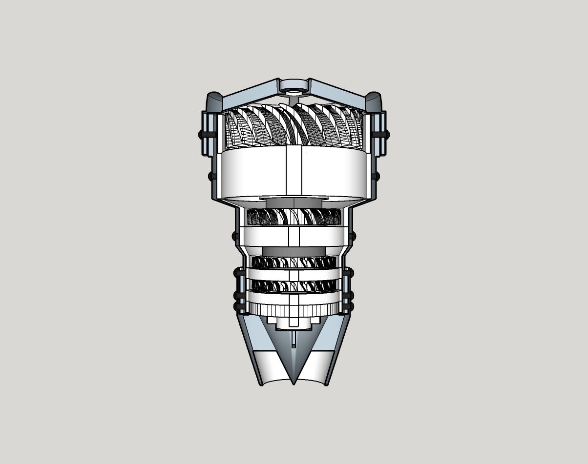
![]()
Front View
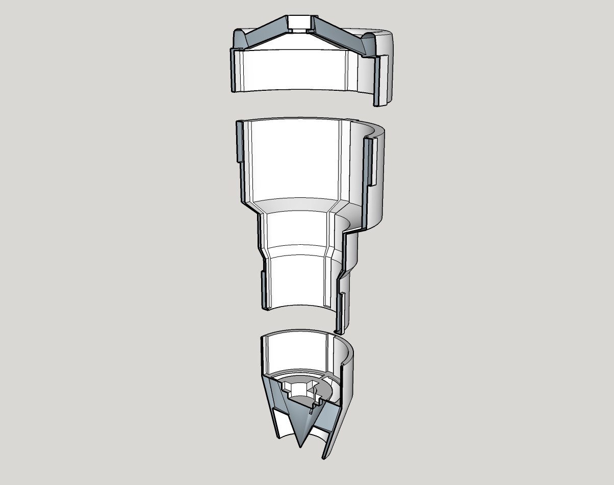
![]()
Just the case
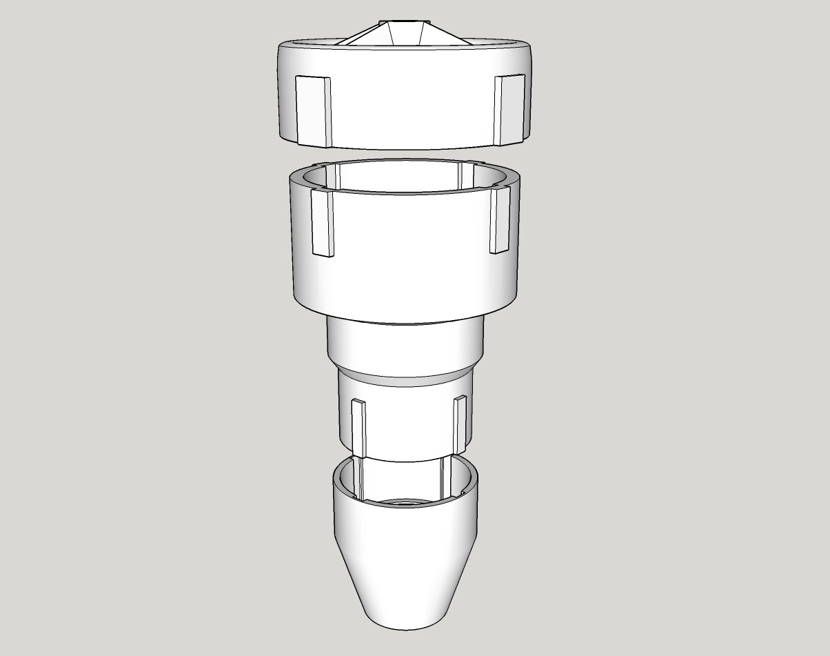
![]()
Full Case
In addition to all that, I've finished printing everything and I've commissioned the main-middle part of the case to be 3D printed (I don't want to babysit a 40hr print). That should come in within the next few days so within the next couple weeks I should have a physical prototype.
I'm submitting this to the Wings, Wheels, and Walkers HAD Prize so wish me luck. I'll keep you all updated with more as it comes!
-
Outlet Guide Vane Finalized
05/28/2017 at 21:58 • 0 commentsSo I gutted my program and was able to retro-fit it to create an outlet guide vane. I then incorporated it into the clam-shell case which I won't attach a picture of because it doesn't change the aesthetics very much.
As stated before the outlet guide vane is designed to de-swirl the air that is exiting from the final stator. By taking out the swirl from the air a smoother combustion can rake place inside the combustion chamber (which doesn't apply here), and by smoothing out the air, more thrut is produced.
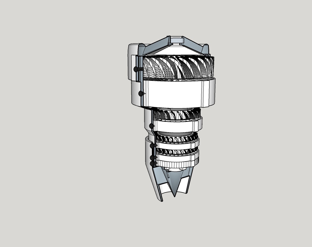
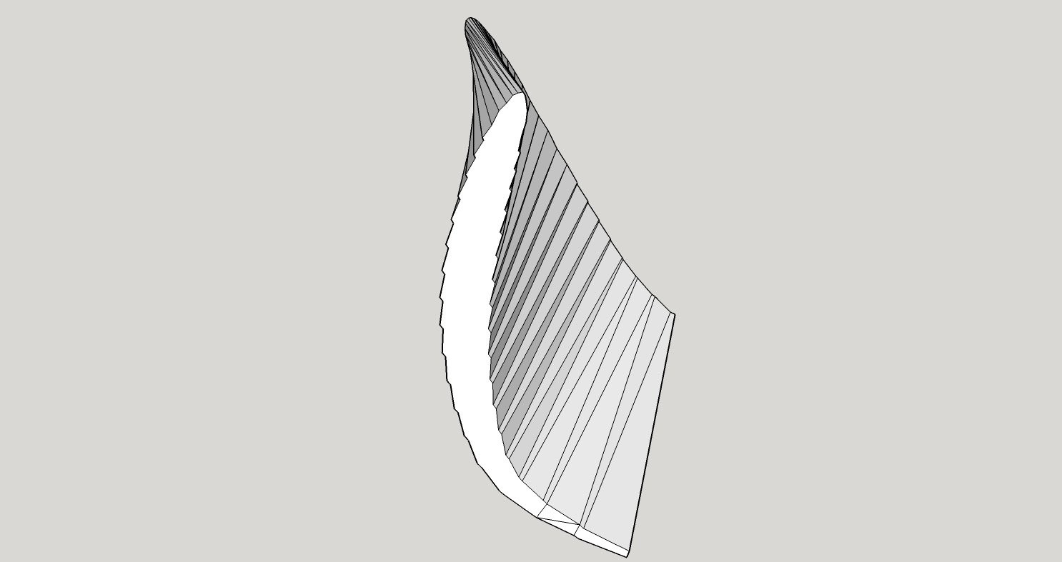
Here is a render of the blade shape. Notice the incidence angle compared to the outlet angle.
![]() Don't mind jagged edges, that's just an artifact of the render, they're smoothed out in the vane.
Don't mind jagged edges, that's just an artifact of the render, they're smoothed out in the vane.And here is the finalized outlet vane that was incorporated into the clam-shell case.
![]()
I will update the STL files to include the changes.
-
Outlet Guide Vane Rough Calculations
05/22/2017 at 14:01 • 0 comments- Alright so I finished doing some calculations on the outlet guide vane parameters. As mentioned earlier, this final vane is designed to "de-swirl" the airflow of the air that's exiting the final stator. The whole purpose of the guide vane is to allow for maximum combustion of the fuel when it enters the combustion chamber, however since I'm not building one of those that doesn't apply. But, it has been shown that having a a straight flow of air increases the thrust produced, hence why jet engines have an outlet guide vane after the last row of turbines.
Anyways, here are my caluclations:
- Number of blades: 17
- ___Blade Angles___
- Inlet: 22.194
- Outlet: -45.249
- Incidence: -5.011
- Deviation: 45.249
- Camber: 67.4443
- Stagger: -16.538
In addition to those angles, like stated before, I also plan on doing a deviated blade, one that has a different angle of attack at around 1/3 of the length. This angle will be around 45 degrees.
So because of all these weird angles - if you can imagine a stage with an inlet angle of 22 and out of -45, I have to re-write my blade construction program. Also note, because this isn't considered a "working stage" it doesn't have the three stage variables:
I'll update this once I've re-written the program and have a 3D model to show you all.
Until next time.
-
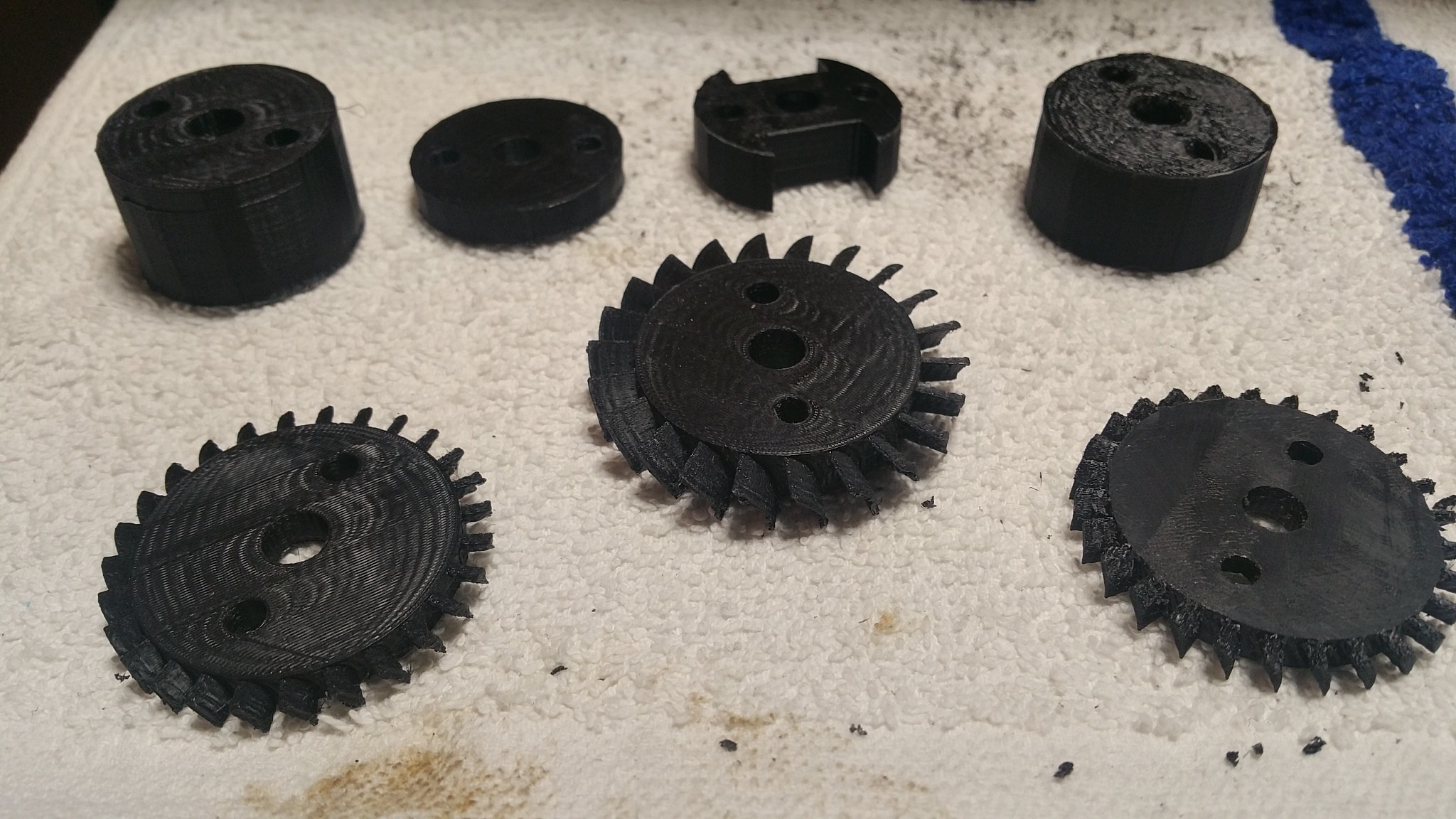
Rotors Complete
05/21/2017 at 22:43 • 0 commentsI apologize for the long overdue update. It's been a rather obnoxious couple of weeks. I've been attempting to re-print the rotor section and got through most of the pieces, then when printing the first (and largest) rotor, my printer broke. So after fixing it, I just finished printing, and assembling the rotor section.
![]()
![]()
To my surprise, I designed this very well and everything fit together. So these picture of it the separators and rotors screwed together.
What I need to do now is give them an acetone vapor path, smooth out those rough edges.
Whats next is to get my CNC up and running. This is just one of those Chinese desktop CNCs, real cheap and easy to use. I'll be using the CNC to build the ball-bearing housings out of aluminum.
![]()
I can't 3D print this for a number of reasons:
- The bearings generate a considerable amount of friction heat
- The oil used to lubricate the bearing might not mesh well with plastic
- The alignment and the major stress of the compressor on placed upon the bearing housings, so having them 3D printed won't give as accurate of a shape as milling them.
I'm also going to commision the compressor casing to be printed so I'll be looking into hubs on 3DHubs.com
To be continued
-
Fixed Rotor Assembly
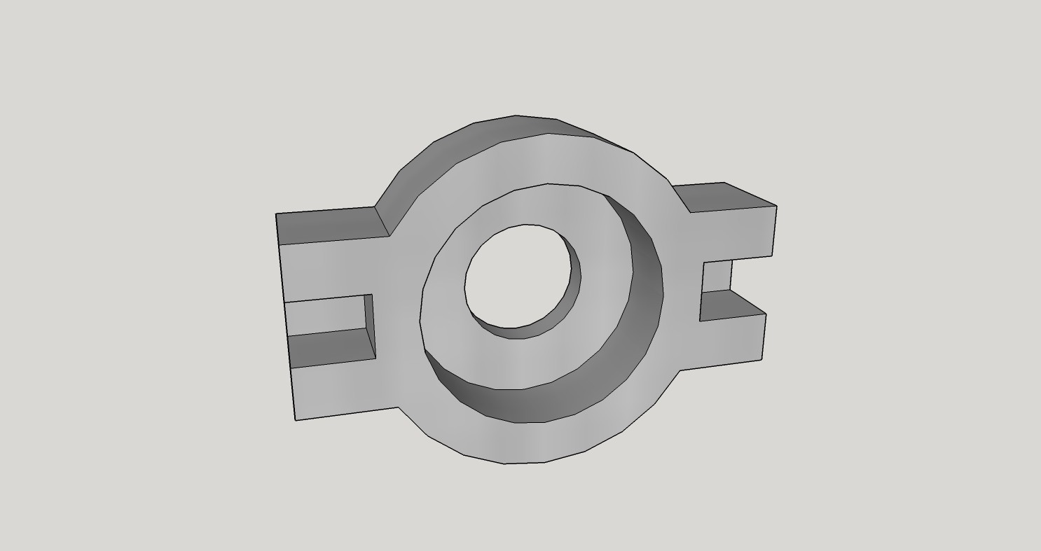
05/05/2017 at 03:07 • 0 commentsI was at work today doing really nothing and it hit me, the rotors couldn't be supported solely on tension and the two screws - they'd eventually become misaligned. So what I did tonight was, essentially, make them Lego-blockey. They're all slotted to fit into each other, this way the stress from the rotation is dispersed to all dynamic piece. So I guess I'll need to reprint all these again....
I've attached a graphic of what I'm talking about.
Lemme know if ya'll have any questions, I'm still trying to update the techniques used as I go along.
![]()
-
Outlet Guide Vane and CompPy Screenshots
05/01/2017 at 22:36 • 0 commentsI'm trying to play catch-up with what I've got and what I've documented, all why juggling work.
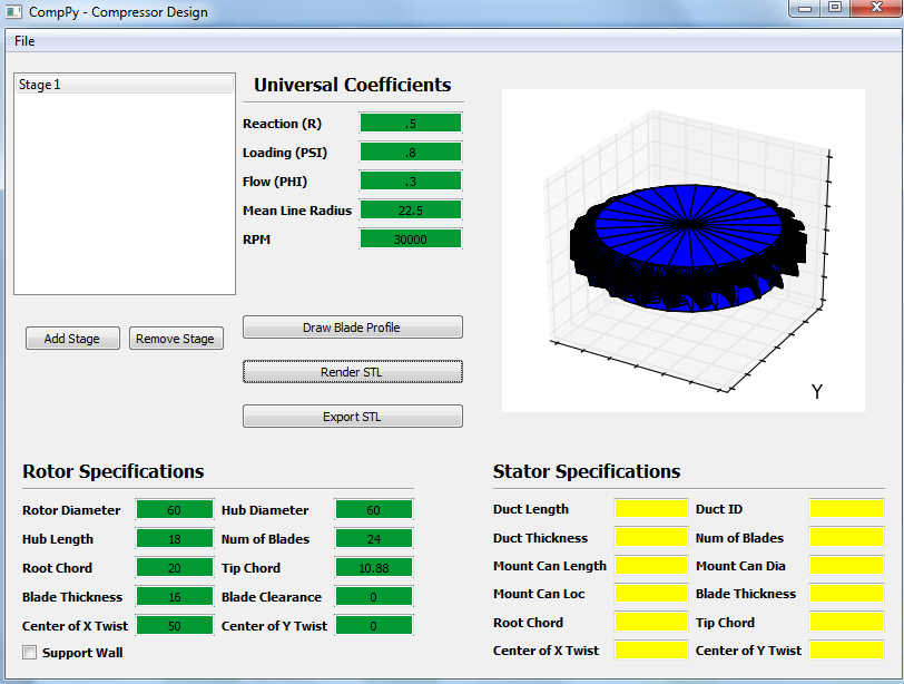
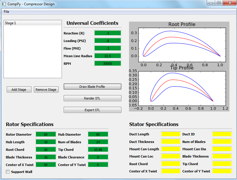
Anyways, I decided to attach some screenshots of my program CompPy. This is what I used to build my rotors and stators.
- The first picture is a final render of a rotor. This can be exported and finalized in an external CAD program.
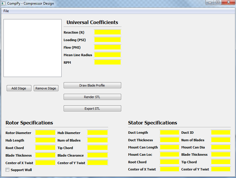
- The second picture is the blank program you see when you first initialize it
- And the third picture is the NACA blade profile for the object you're building
I'm still working on making it an executable so people without Python can run it.
![]()
![]()
![]()
The next thing I'm working on is a design for an outlet guide vane. When the air is exiting the final stage it has a swirl which is created from the final stator. If a combustion chamber was installed the most efficient burn would occur if the air was relatively straight, to achieve this an outlet guide vane is installed.
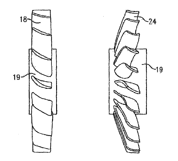
I calculated that I'll need an outlet guide vane that has 17 blades. But instead of just a regular blade, there is another and better option. In 2012 a patent was filled, (Patent Number: 8,333,592 B2 for those interested) that showed that having an outlet guide vane with a blade that had a different angle of attack about 30% the length.
I'm probably not explaining this correctly so attached is a picture. The left diagram is a regular outlet vane and the right one is with the increased swept.
![]() So this weekend I'll work on a model and try and print it.
So this weekend I'll work on a model and try and print it. -
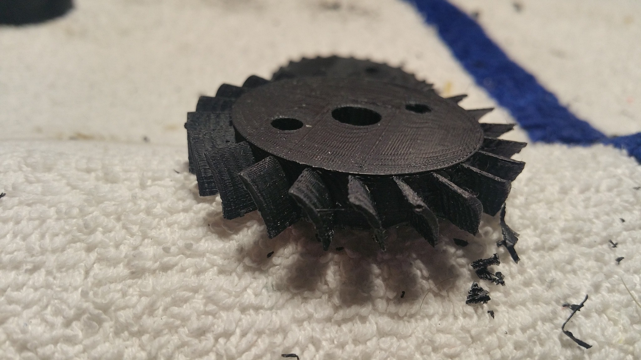
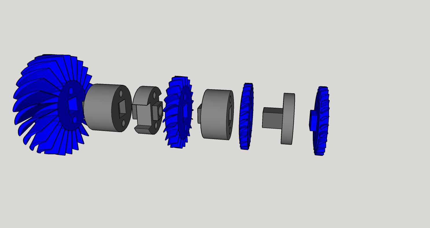
Stages 2,3,4
05/01/2017 at 00:10 • 0 commentsPrinted the rotors for Stages 2, 3, 4 and the spacers and the coupler models, these still need to be finished and cleaned.
I haven't printed Stage 1 rotor because it's going to be an 18hr print, so I need to devote a weekend to that.
To give some sizes:
Stage 2 is 27.8 mm in diameter and 10 mm long.
Stages 3 and 4 are very similar, both being 24.5 mm in diameter and 6 mm long.
![]()
![]()
3D Printed Axial Compressor
An axial compressor that is designed to be produced inexpensively by the daily hobbyist
 Don't mind jagged edges, that's just an artifact of the render, they're smoothed out in the vane.
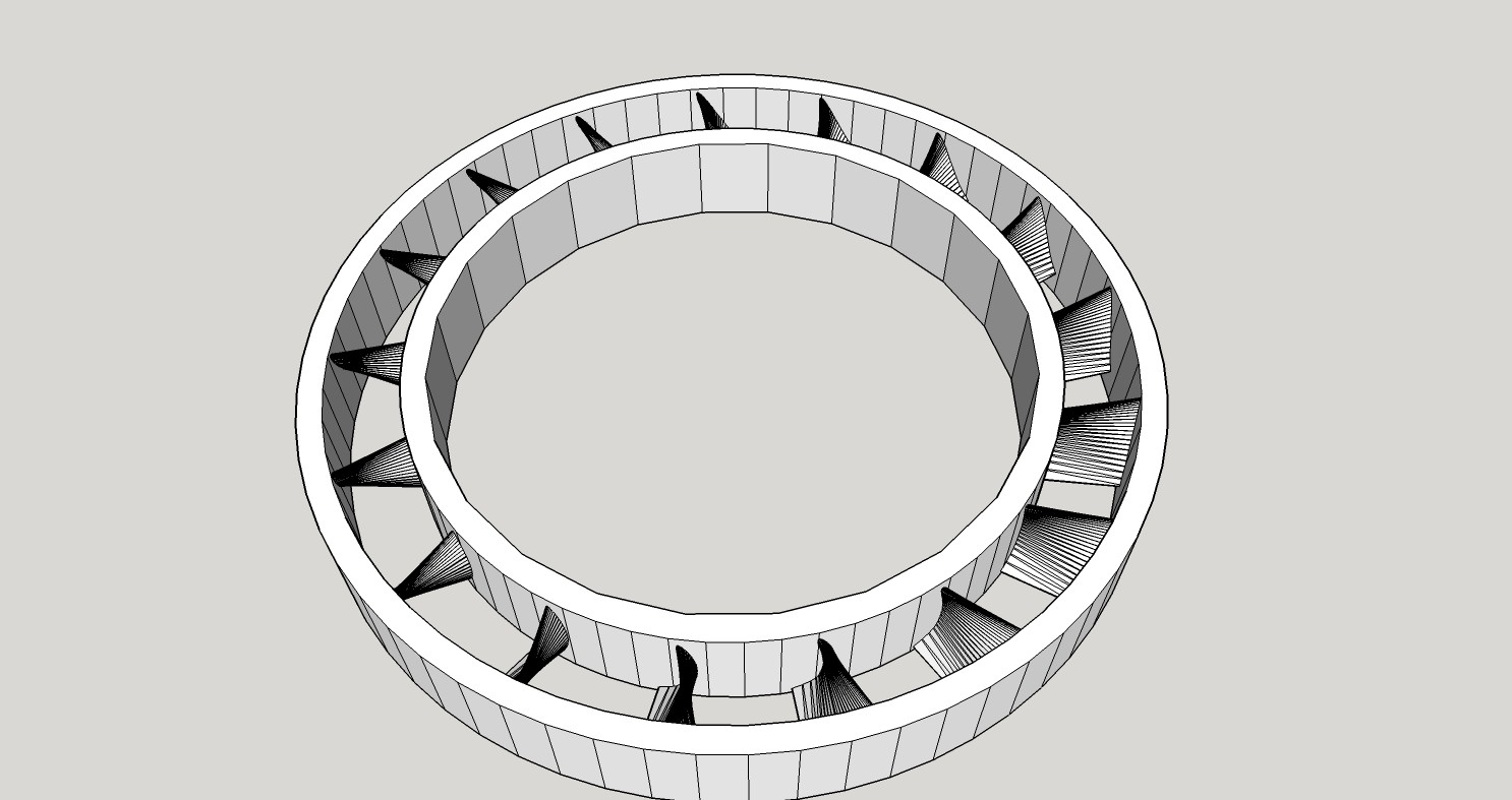
 So this weekend I'll work on a model and try and print it.