timonsku
-
Still alive.. new prototype!
01/03/2016 at 19:21 • 0 comments"I will definitely finish this over the next months" heh.. no.. I lied.
But I got back to it and completely revamped the hardware and just finished a new prototype.
The results I get with this new prototype are a LOT more promosing than what I got so far.
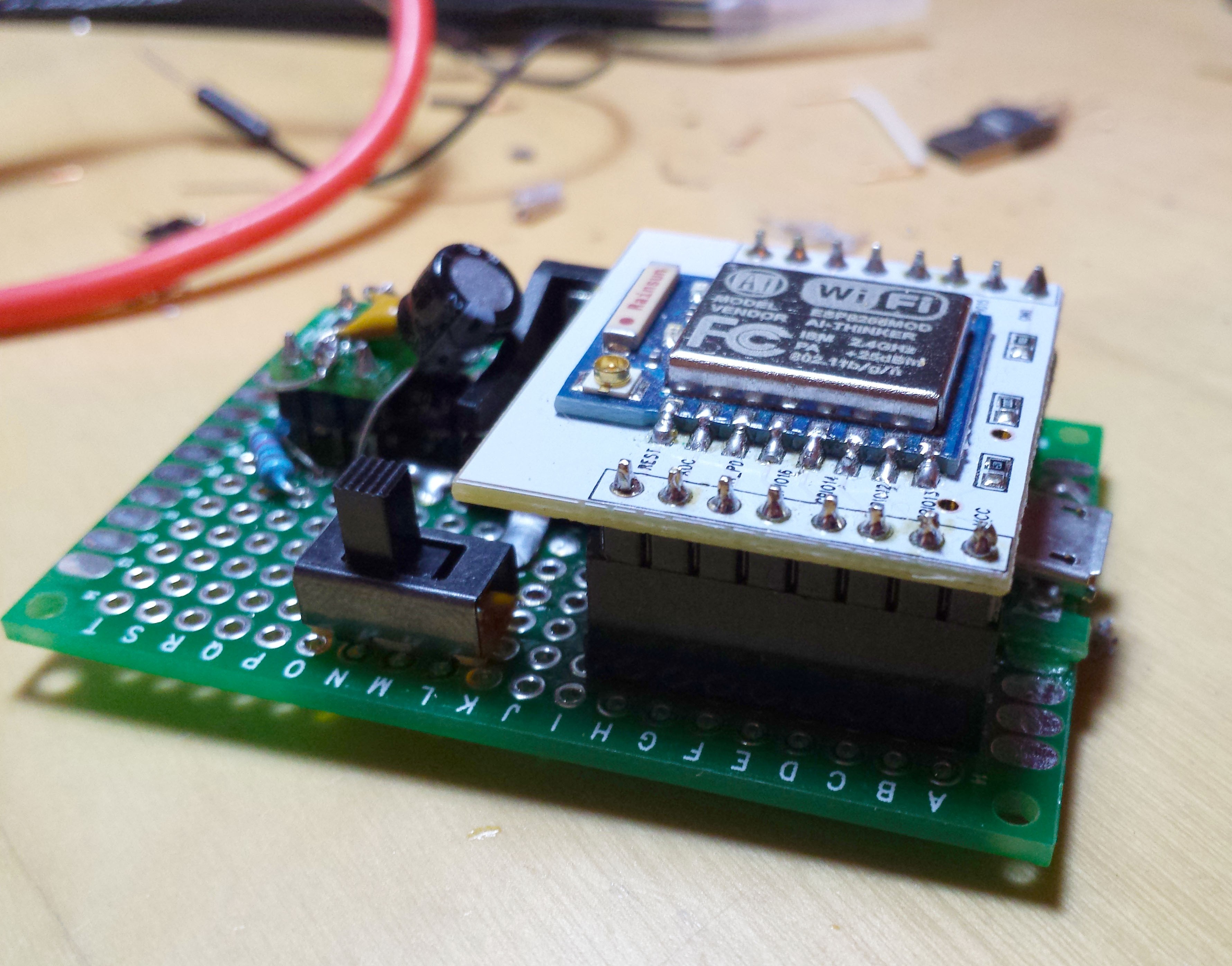
Instead of the old ATtiny setup I used just an ESP8266 and a MCP8421 18bit ADC. I found that I don't need the 18bits but given that the ADC is fairly accurate I can get a pretty clean reading at 12 bit and 8x amplification (using the built-in amplification).
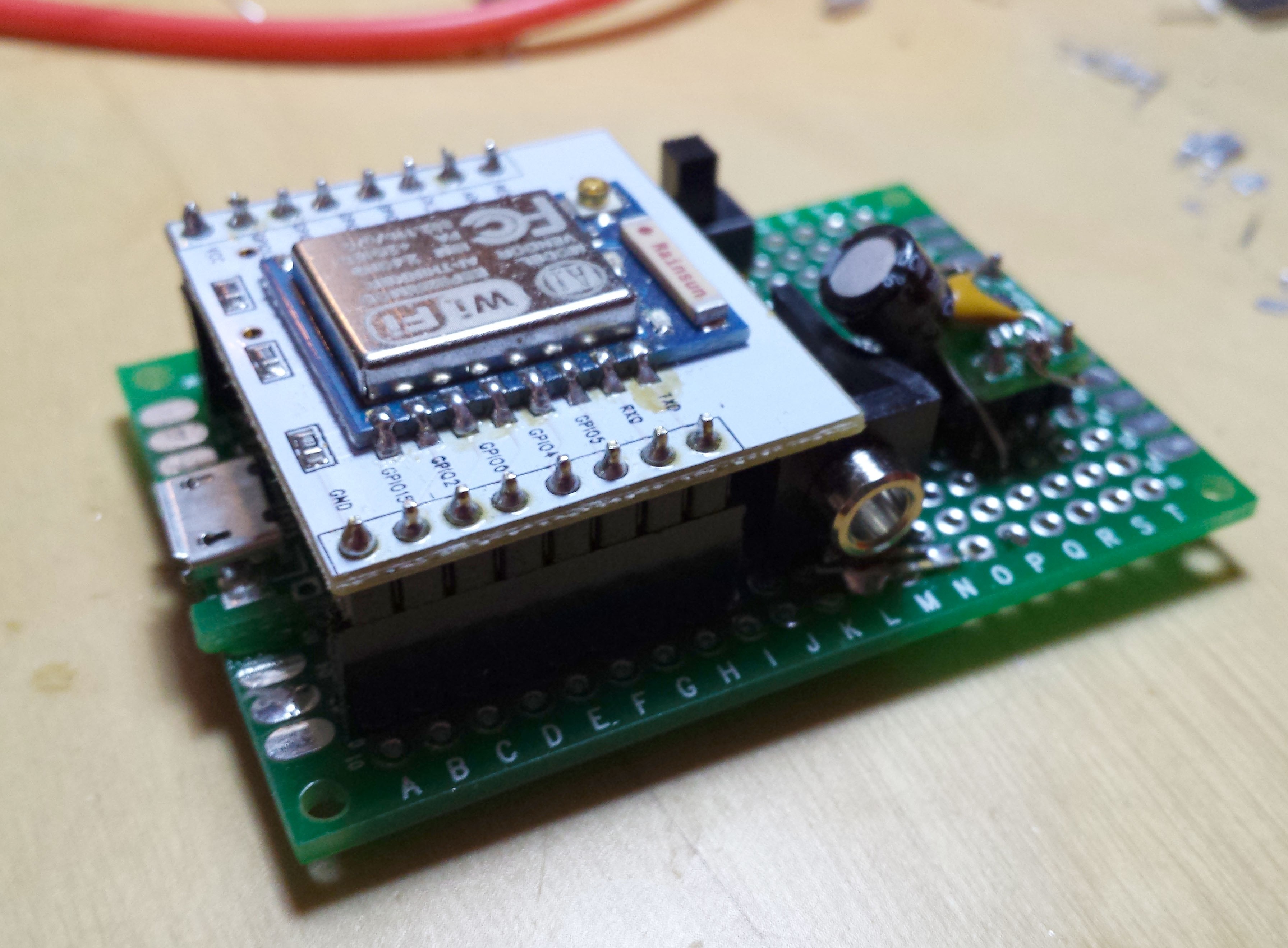
This is how the new prototype looks like:![]()
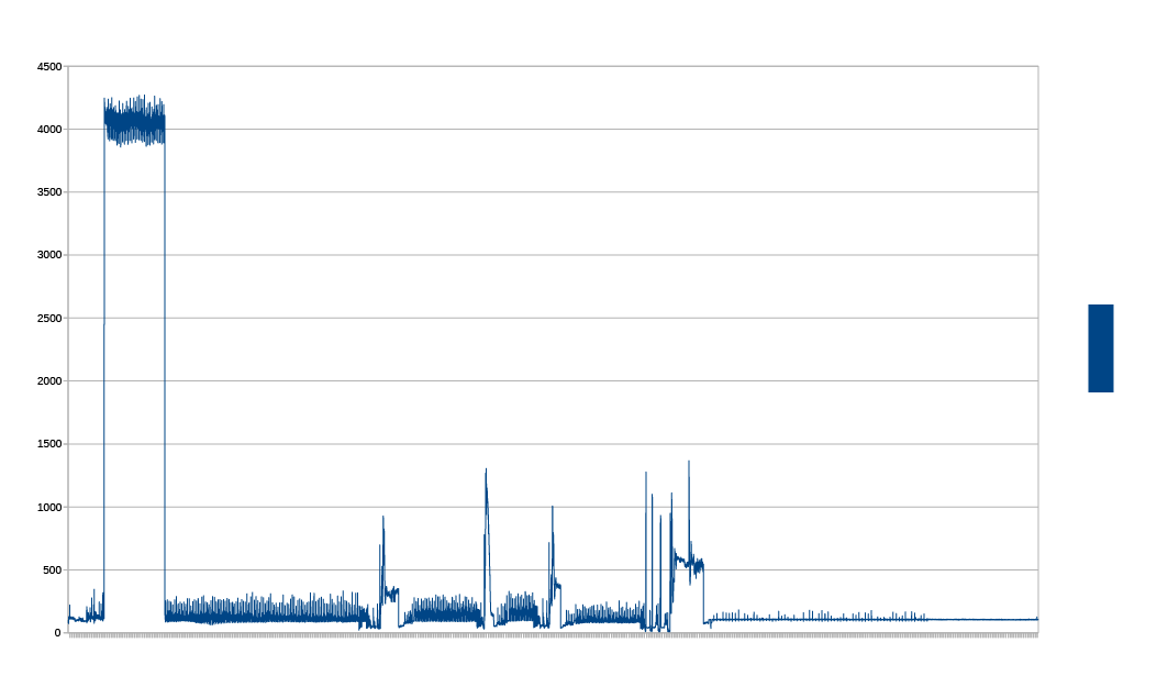
![]()
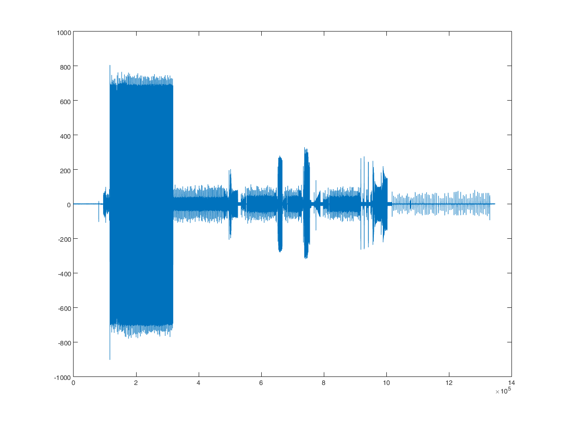
And this is a sample reading. Having a differential reading makes a huge difference. I didn't think about it before but with AC current it doesn't really makes sense to do anything but a differential reading because otherwise you get nothing at all half of the time.
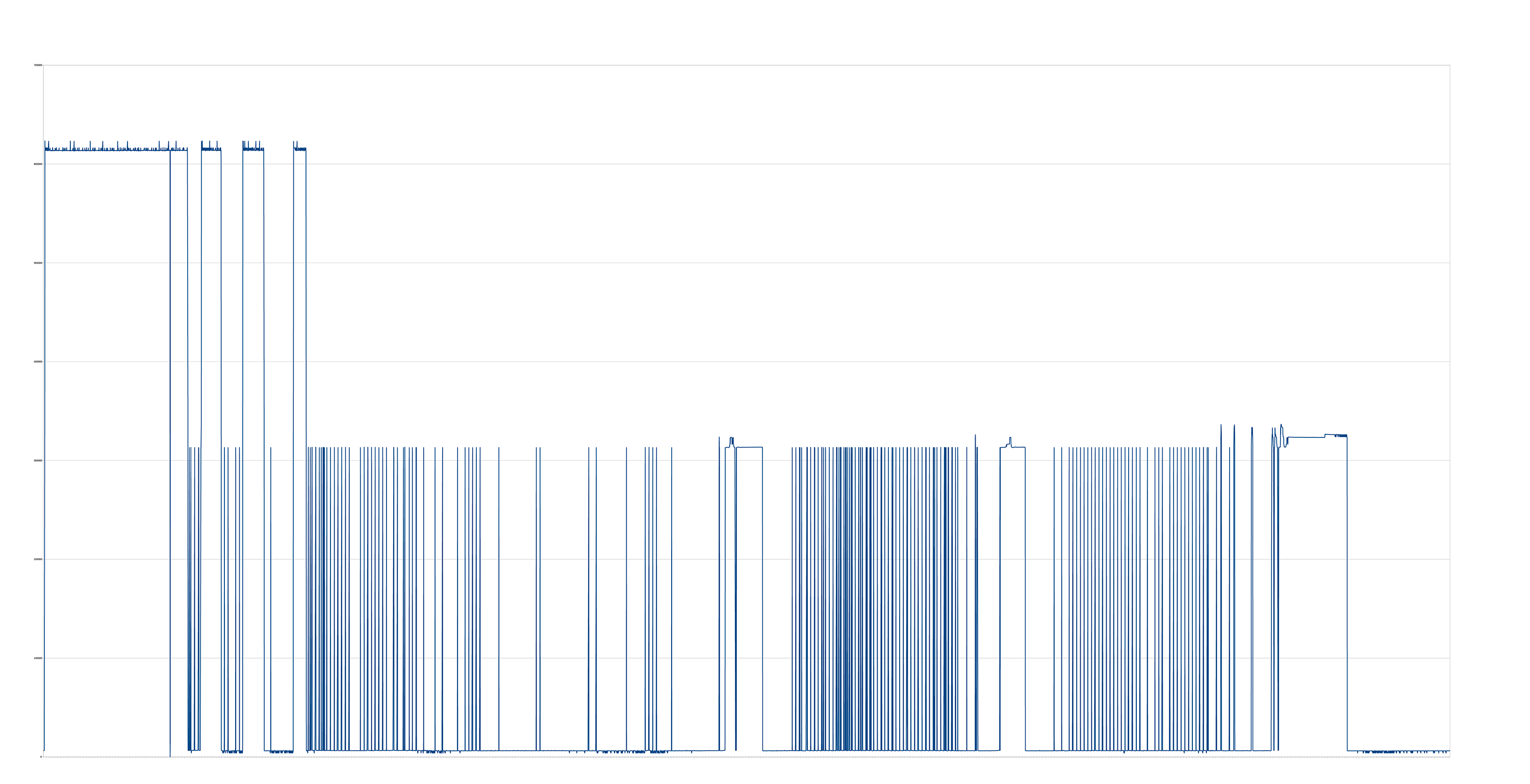
What I also changed was the resistor in the CT clamp. By standard the 30A version I got has a ~38 Ohm shunt resistor. The smaller the resistor the higher the resolution per mA but what I really needed was to scale up what I get so I soldered a 50k Ohm resistor in there and got a much better respond to smaller currents as the voltage drop increases. Should be noted that I still have a somewhat half knowledge in this area but the result was what I wanted.![]()
Now I will run some extended tests and if all goes well I will incorporate the new sensor board into my old software and write an algorithm for my machine. With the values I get this should be fairly easy. I found that every washing machine behaves completely different so you will always have to write a new algorithm for a new machine or implement some sort of end-user assisted machine learning algorithm.
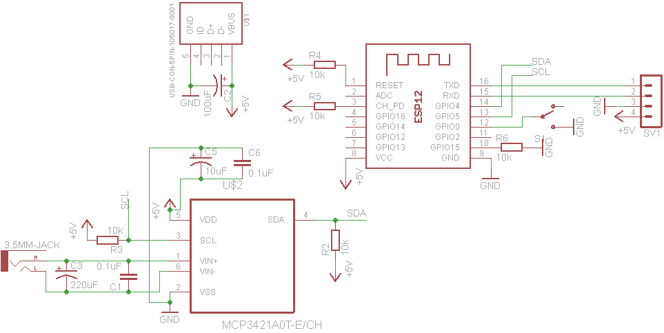
I also made a schematic of the new board if anyone is interested. Maybe I make a PCB later on when I finished testing.![]()
-
It's not dead
10/17/2014 at 23:35 • 0 commentsI haven't posted any updates in a while and I haven't done anything in a while but I will definitely finish this over the next months, my hands are currently full with lots of new "life stuff". As soon as that has smoothed out a bit I'll try to find someone who can give me some input on improving the sensitivity of my energy monitor, as I started studying electrical engineering a few weeks ago I hope one of my professors might be able to give me a little support.
The reading sensitivity is really the only part that keeps from continuing, so if someone can help with some practical advice or some example schematics for an op amp circuit in this use case would be really helpful. -
Failing with Op-Amps
09/08/2014 at 20:08 • 1 commentSo I did get a few Op-Amps but absolutely failing at getting the circuit to works, I just don't get any amplification.
I'm currently trying to use this (seemingly common) circuit:http://hyperphysics.phy-astr.gsu.edu/hbase/electronic/opampvar2.html#c2
Maybe I need actually negative voltage on V- and not ground?
Though I did get a few better results by using a 1k resistor instead of a 33ohm one. 33ohm assumes 100A which is just bullshit in this application, I dont want to measure a whole house hold just one appliance which can't draw more than 16A. Considering the washing machine I test with is also far from using 16A I opted for around 3A. Though the result is still not satisfying, beginning and end of a run is still not spiky enough to have an easy to write code to detect it. The noisy part at the front and end is how the current usage looks like towards the end but the noise also appears sometimes when idle.![]()
-
Improving the sensor readings part 2
08/22/2014 at 21:44 • 0 commentsSo I read a bit into current to voltage circuits and seems the resistor only approach is pretty bad. Using an op-amp as a virtual ground seems to produce quite a lot better results, those guys are super cheap so that doesn't add much/anything at all to the bom.
I will pick one up tomorrow and see how that goes. -
Improving the sensor readings
08/20/2014 at 22:47 • 0 commentsWhile I'm waiting for my VoCore to really advance with the project, I'm thinking about ways to improve the accuracy of my sensor readings. I actually get enough information to determine if a machine is running and can somewhat tell in what state it is in but I'm depending one some very specific spikes that happen at the beginning and end of every run.
Right now the EmonLib is giving me basically three different current states with a bit of noise in each state.
Here a data plot of a complete run (right click->view to see it in full size).![]()
The flat thing at the end is how its supposed to look when it idles but you guessed it, it doesn't always look like that. I get a spike to the mid level from time to time which really messes with how I want to write the software. I'm not able write complicated algorithms that can handle this random spiking.
If thats even possible, as a single spike sometimes means the start of a run and then minutes of just nothing until the machine goes into overdrive. So I will have get rid of this spiky noise that occurs in my circuit. I somewhat suspect that the RF transmitterthat is pretty close to everything else might play a role in that.
I will try and see if the RPi directly connected to the sensor board has similar issues or if gets better. I might also try to shield the board somehow, the surrounding machines might emit quite a lot off electro-magnetic noise. Unfortunately thats a topic I'm not really familiar with yet so I have to read into quite a lot of stuff to understand and fix this issue.
I will also look into dedicated energy monitor boards and see what they did.
Regarding scematics, so far I don't have any. The circuit is pretty simple and I just did it on the go. The CT sensor circuit is just a copy of this circuit here:http://openenergymonitor.org/emon/buildingblocks/how-to-build-an-arduino-energy-monitor-measuring-current-only
And yes I could also just use the full board from this (really great) project but thats just too much for this purpose, current is absolutely enough and I want to keep costs and complexity as low as possible. -
TFT backlights make for a cheap Softbox
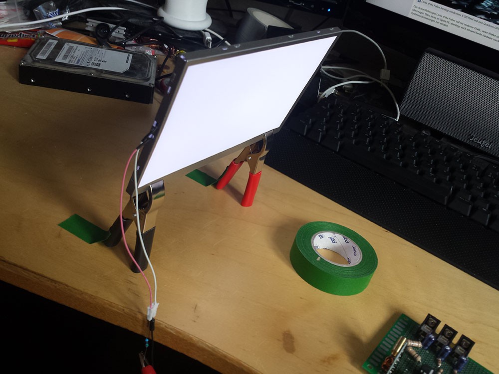
08/20/2014 at 13:55 • 0 commentsNot really related to the project but I recently dissembled a few broken TFTs and found that their backlights can be pretty bright if you remove the panel. In the case for my project video I used the LED backlight of an old digital photo frame. Its not super bright but is useful if you want a nice soft light on your object to let the glossy parts really shine.
Here is a photo of it:![]()
I also dissembled a huge 30" TFT which has an LCD backlight which is FAR brighter and is really useful as bright softbox for larger objects.
-
Project Video
08/18/2014 at 21:42 • 0 commentsI nearly forgot about my project video so I here it is. I mostly used the text out of my description, so if you werent lazy and read the text you already know everything from the video.
For those who prefer to listen instead of reading, watch the video:
-
System Design
08/17/2014 at 18:44 • 0 commentsOne of the requirements for the HaD Prize entry is a system design document, so here it is. Basically tldr of what I wrote in my detail description.
You have small and cheap sensor board that connects to your machines via CT sensors and the current values from these sensors are turned into a voltage signal that an MCU (ATtiny) picks up and sends it wireless to the server.
I put the RPi in dotted lines as I may replace it later on with an small MIPS board with Wifi and Ethernet built-in that sits on the sensor Board and receives sensor data over serial/i2C/SPI. That would make the whole thing most cost effective and smaller and everything is one neat package.
![]()
-
Code
08/17/2014 at 15:16 • 0 commentsI've uploaded all my code to GitHub now under the GPLv2 license. All libraries used in my project are under the MIT license.
It's not exactly well written I dont have too many years of coding experience but I tried my best to make it not confusing but readable. After all the code is pretty slim so there is not thousands of lines of code to understand here.
The most work in terms of lines went into the client so far.
The code is not fully functional right now, the part to parse the sensor data and set the machine states accordingly is still missing. More on that in another log. Other than that you can run the server on your local machine and try out the user interface in action. BE AWARE that the user interface is currently 100% smartphone optimized, while you can use it on a dektop it will look like shit.https://github.com/PTS93/Laundrify/
-
What I did so far and plan to do next
07/27/2014 at 16:13 • 0 commentsMy initial plan was to use a Raspberry Pi to connect the sensor board wirelessly to the internet. The Pi currently has a 433 reciever to get the sensor values from the ATTiny and is connected via LAN to the internet.
This has several issues. A) the Pi is rather expensive and overpowered to just connect something to the internet and host a simple web server. B) Cheap 433Mhz transmitter/reciever suck donkey balls regarding range, especially indoors.
I really didn't want to spent much money on the project when I started out so I opted for the cheapest solutions possible. I changed my mind a bit as the project was interesting to do for me so far (I'm still a huge noob with electronics) and I want to make a better hardware but with a low price still in mind.
So my plan now is to atleast ditch the 433Mhz transmitter and opt for LAN or a NRF24l01+ 2.4GHz transmitter, which have a better range when properly configured.
My preferred solution would be to also ditch the Pi and go for a "VoCore" which I recently saw on Hackaday. It's a 20$ Wifi enabled MIPS board that can run OpenWRT. The plan would be to directly put this cute little guy on the board and connect it to the ATTiny via serial/spi/i2c.
I have already written a huge part of the server in Node.js aswell as the client front end. The client communication and user management is already done, what is still missing is the sensor value analyzing to determine if a machine is running. Which is more difficult than expected as the sensor board is not exactly accurate.I will probably have to redo some stuff in order to get a more accurate reading. It's absolutely possible to tell that a machine is running but with a delay of ~15-20 minutes which is not acceptable. It also has possible "false alarms", sometimes the ADC reading spikes without anything happening or sometimes it misses an important spike when starting a machine which leads to the said delay.
I pretty much copied the CT sensor part from the great Open Energy Monitor project (http://openenergymonitor.org) and didn't entirely understood their circuit to convert the amps from the ct sensor into a voltage. Now that I have a better understanding I hope I can improve the accuracy of the readings.
Laundrify
A system to monitor shared washing machines in a house(hold) that notifies you when your machine is finished or one becomes available.