Szabolcs Lőrincz
-
Laying the tracks
07/25/2015 at 13:52 • 0 commentsAfter a successful test run, it was time to take my build to the next level. Instead of using copper wire and soldering, I came up with a much better solution: tape the track surfaces with conductive foil. After a short searching, I found this on ebay. It works perfectly, low resistance, easy to work with, solderable. Also, the tracks look somewhat better now.
![]()
I also modified the models a bit. I added pantographs on the bottom of the train, and recycled the old one as a cargo wagon. They don't need any source of electricity built in anymore, as the power comes from the rails.
![]() Furthermore, I put a very simple and primitive remote control for it. The train is powered by 2pcs of AA cells wired in series, thus providing around 3 volts. The train is controlled by two SPDT buttons, for both directions. They are making a full H-bridge, basically. Finally, I made a switch, which is indeed important if you want more trains. It is operated by two solenoids which I printed myself, and coiled with a drill. I designed a driver circuit for it which also drives the LEDs showing the position of the switch. The driver circuit limits the on-time of the solenoid to about 1-2 secs, so that they consume less power and don't overheat. This will also make the programming easier, as you only need to set a pin high to switch without having to add any delay or something. But for now, it is also controlled manually by an SPDT switch.
Furthermore, I put a very simple and primitive remote control for it. The train is powered by 2pcs of AA cells wired in series, thus providing around 3 volts. The train is controlled by two SPDT buttons, for both directions. They are making a full H-bridge, basically. Finally, I made a switch, which is indeed important if you want more trains. It is operated by two solenoids which I printed myself, and coiled with a drill. I designed a driver circuit for it which also drives the LEDs showing the position of the switch. The driver circuit limits the on-time of the solenoid to about 1-2 secs, so that they consume less power and don't overheat. This will also make the programming easier, as you only need to set a pin high to switch without having to add any delay or something. But for now, it is also controlled manually by an SPDT switch.![]()
![]()
So far so good. Furtanately, everything is working out well. The next big step will be to make the prototypes into PCBs, and finally put the two big parts together, and integrate the electronics into the hardware. If you want to see it in action, watch this video:
-
First steps, test run
07/21/2015 at 19:43 • 0 commentsIt is finally time to assemble the whole creation. The parts are printed, so let's put them together! For now, I didn't use the electronics stuff, I just simply wired an AA cell to the motor to keep things easy.
![]()
The whole engine is switched by a jumper. The axises of the train are made out of welding rods. The drivetrain consists of a really small 3D printed gear and a basic chipboard screw. The screw is secured to the motor shaft by shrink tubes, which were also used as tires on the driven wheels for better grip. I also added a lage nut in the back of the train for more weight. The gear is so small that I needed a 0.2mm extruder nozzle to print, but it was totally worth it (especially because it only cost 2$ off ebay). I will post some instructions when I build the next loco. Here's how the drive looks like:
![]()
![]()
For the first test run, I assembled a simple loop, and let my train run in circles again and again. It was so awesome! Look at it yourself:
-
Newly soldered electronics
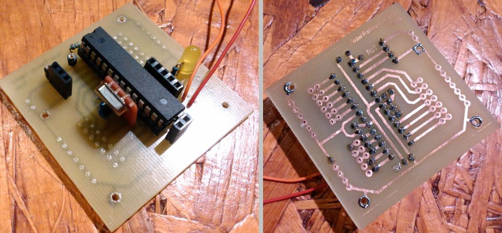
05/26/2015 at 19:35 • 1 commentI recently built the (hopefully) final master station and train h-bridge pcbs. Here are they, just out of the acid, freshly drilled:
![]()
The master station is basically just a breakout board for the ATmega328P. I made a separate crystall oscillator on a small piece of protoboard. I could've went with a ceramic resonator, but I didn't have any at hand, and the crystal is more accurate anyway.
![]()
![]()
Here is the full master board with the mcu, the oscillator, connectors for the serial, power and ISP, and a LED on the usual PORTB 5. All other pins are accessible and there is also space for a pull-down resistor if needed. I've only connected the TWPC cables yet.
![]()
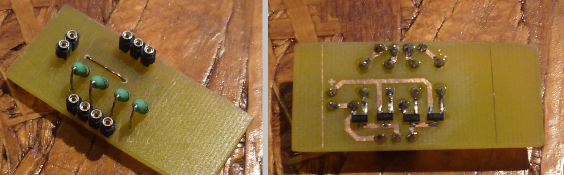
Here is the picture of the H-bridge with the four SMD mosfets. It works great, not like the last one. No shortage, no overheating, drives the motor perfectly.
![]()
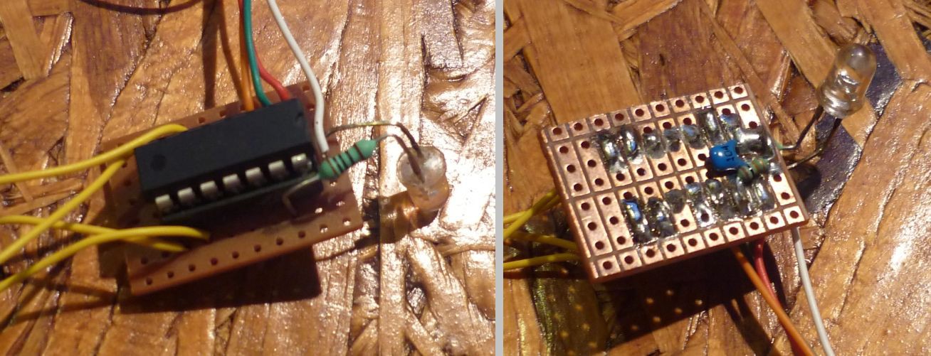
The brain of the train engines is just the MCU itself, it didn't even deserve an own board, a protoboard was just enough. It will be standing in the front of the loco. Behind this will be the h-bridge connected to the yellow wires. The led will be the headlight of the train.
![]()
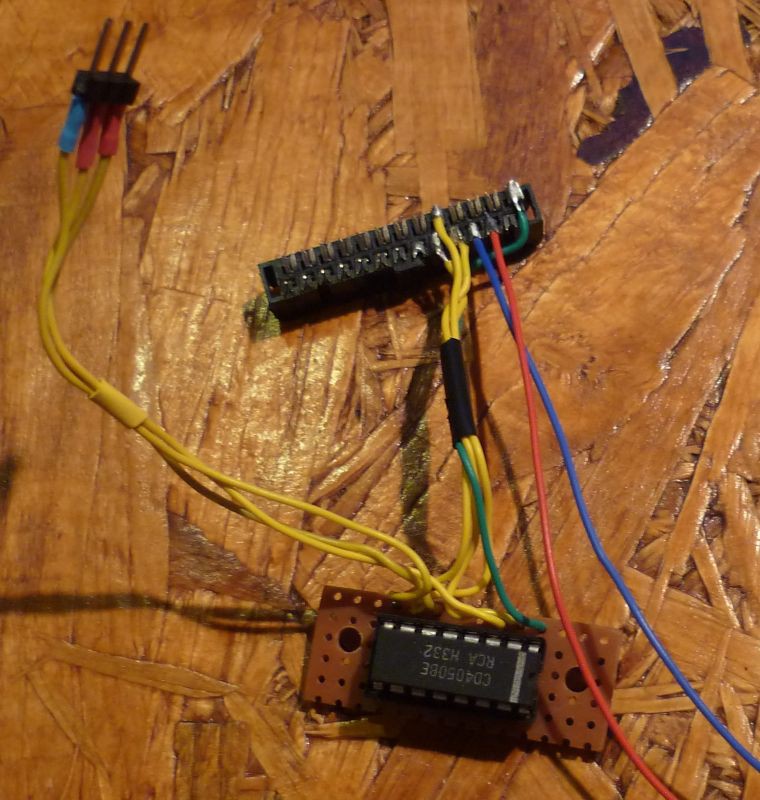
The last piece of the puzzle (for now) is this adapter I made for the raspberry. There is a 4050 ic converting the avr's 5V signal to 3V3, ensuring safe uart connection between the master staion and the pi.
-
First test print at last
05/14/2015 at 10:43 • 0 commentsSo finally I printed the first rails. I came out just fine. The bottom rail is a very early prototype with embedded copper wire for as conductive stuff, it'll be better when the whole thing will be together.
![]()
-
Rebooting
05/13/2015 at 16:00 • 0 commentsGiven up on waiting for Makibox, and ordered another printer from eBay, a Sintron Prusa i3 (take that, Jon Buford). It arrived, and I managed to make it work! So I started working on this project again, brand new code is available on GitHub for the new communication protocol. ( I'm using timer interrupt instead of _delay_ms this time, it's much better). Anyway, first images of test prints coming soon!
-
Motor control FTW
11/02/2014 at 17:01 • 0 commentsAfter a short break, I finally have some update. First, the motor. It works! The H-bridge is perfect, and runs only from the USB power it gets from the MEGA. Also, I get rid of the voltage-divider resistors and get a proper CD4050 for the Raspberry-MEGA UART connection.
I also figured that connecting every device again and again one by one at every power-up can become really annoying. Who wants to do that? Not me, obvoiusly. So I came up with the idea of static IDs. Devices with static ID have to be connected to TWPC line when the master is offline. Then, when it starts, they'll be connected automatically. Connecting devices with auto-assigned ID is still possible though.
Here is the new breadboard setup with the H-bridge:
![]()
That's for the electronics, but that's not all I got. I designed brand new rails with holes and stuff to be modular. I also designed switches (only the static part yet) and assembled a whole train station. Go to my GitHub to see the STL files along with the codes and schematics.
Still no news from the 3D printer...
-
Motor control
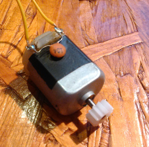
09/07/2014 at 12:48 • 0 commentsI started developing the motor control part. The motor will be driven by a MOSFET H-brigde with PWM. Here's the motor of the train:
![]()
As you can see, It's a basic, common DC motor, nothing fancy.
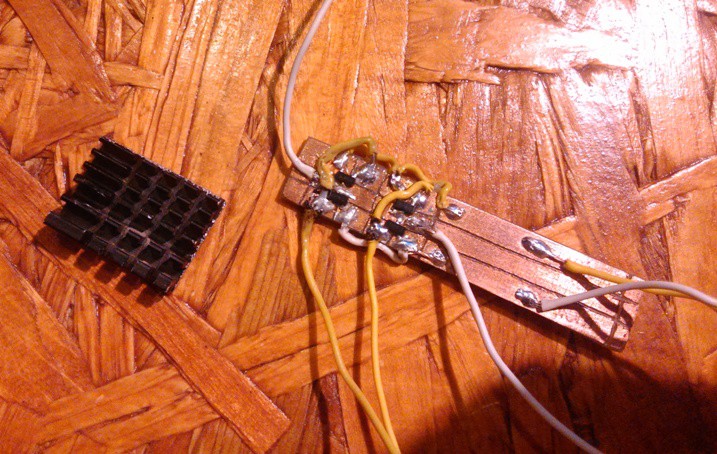
The prototype of the H-bridge wasn't too perfect. It didn't use resistors at all, and I connected the gates together. Needless to say, I burned all 4 mosfets. What a shame. Here is the prototype, may it rest in peace:
![]()
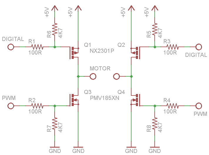
The new design is somewhat better, using current-limiting and pull-up/down resistors. The P-channel mosfets will be used digitall, while the N-channel mosfets will take care of the PWM control. Here's the schem:
![]()
I look forward to se how that'll work.
School started recently (yay :/ ) so I have less time to development. I hope I can try this out next weekend though.
-
Power on hands
08/20/2014 at 19:38 • 0 commentsFinally managed to power the AVRs through the TWPC bus. It won't drive a motor yet, but it's enough for the MCU and some LEDs.
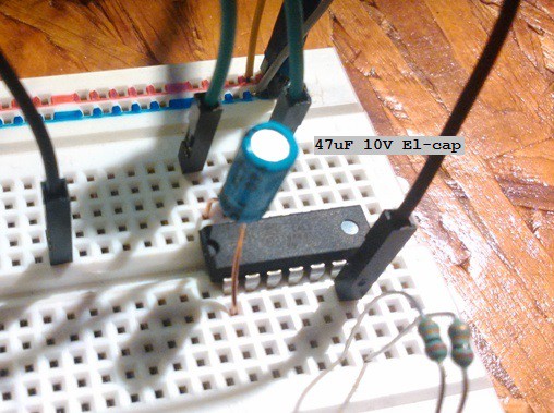
I added a 47uF capacitor to the AVR's Vcc and GND legs. The energy comes from the data pin through an internal diode and stores in the cap for stable and continous power.
![]()
-
Model Railway control over the interwebz
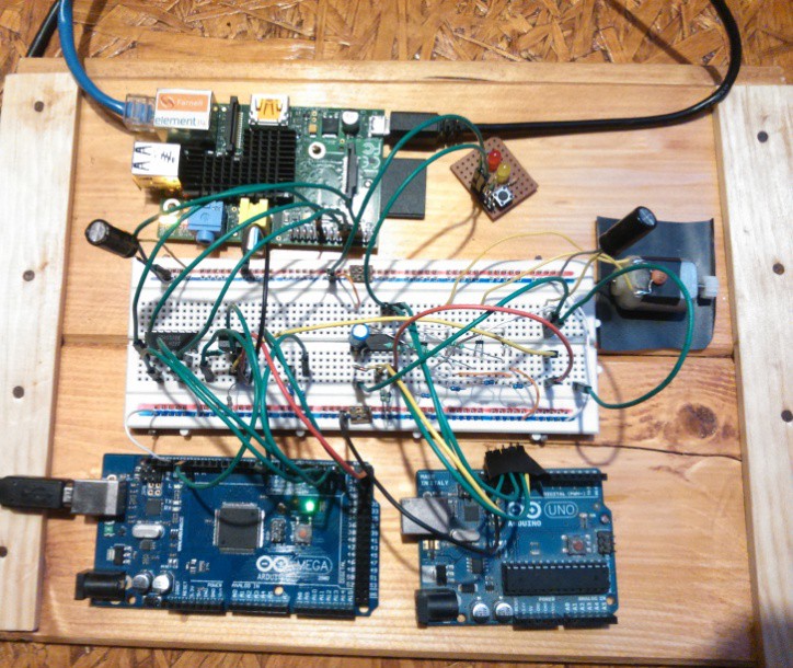
08/20/2014 at 15:35 • 0 commentsNow that the circuit is complete, let's see the controls. The model railway is connected, meaning you can control it from anywhere from any device with a browser. All you need is a RaspberryPi and internet access. The Raspberry runs Apache2 with the control panel, and it communicates with the master station through UART. Then the masters sends out the commands for the slave devices through TWPC. You can control every device with one click.Looks like the electronics is almost done, here are some picures of the results so far:
![]()
![]()
-
One-wire communication protocol
08/05/2014 at 17:48 • 0 commentsThe next step is the communication. Not the main protocol, that will come later. This is for determining position. There will be metal plates between the rails and a contact on the bottom of the engines. When these touch, the engine's AVR will sense the pulse and send back its ID. That's all. For now, I prototyped this with an Arduino UNO and MEGA.
![]()
The communication flow through the yellow wire. There are 10K pull-down resistors to prevent catching noise in contactless state. I even draw a schematic.
![]()
That's all for now. More details and source code on my website and on GitHub.
Broke Hackers' Model Railway
Cheap, fully automated model train system with 99.9999% 3D printed parts.