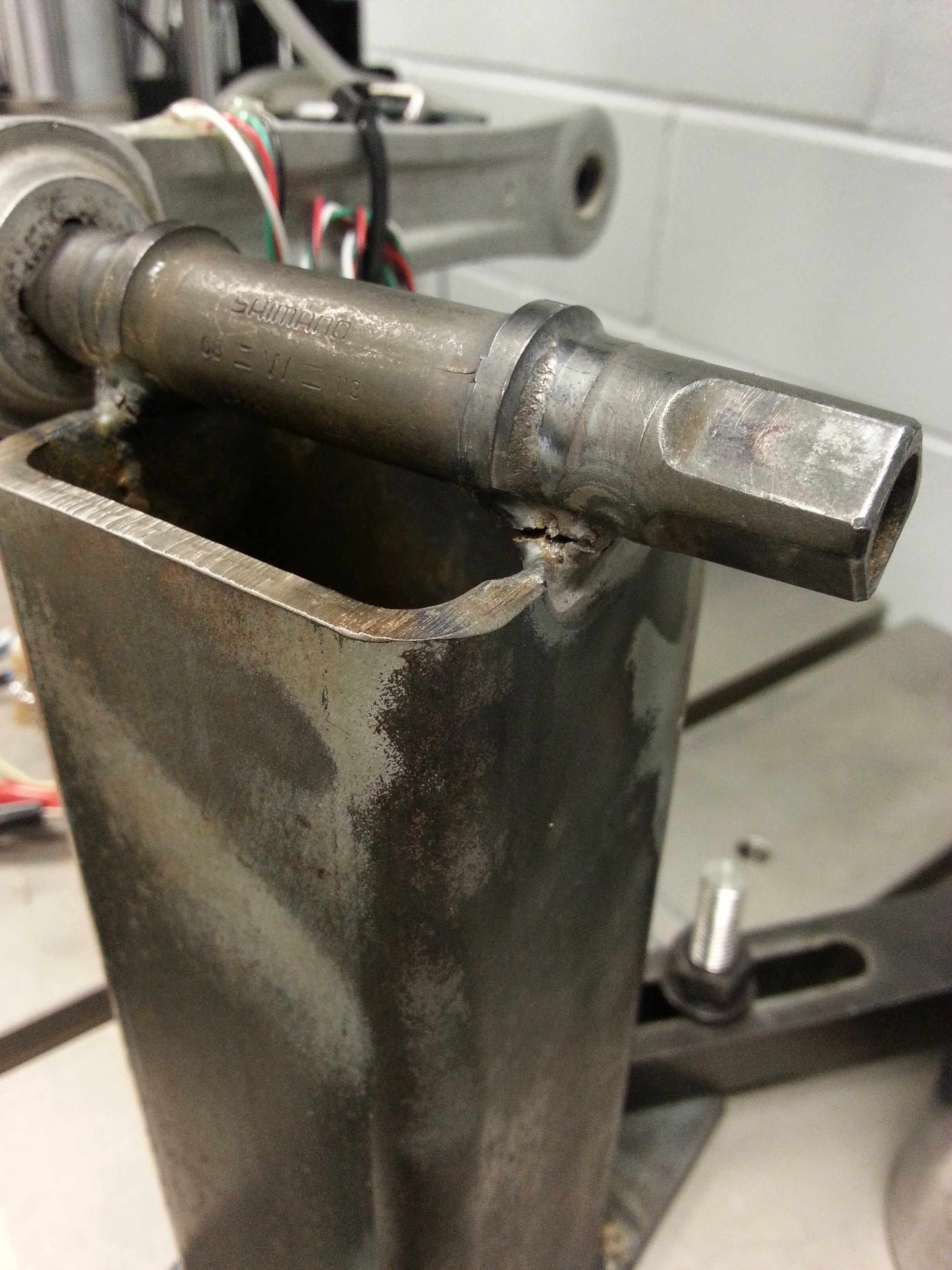
Project will be broken into phases. At the end of which there will be a working prototype that may be further refined for aesthetic reasons (i.e. smaller):
Phase I: Instrumenting a Crank Arm
Goals:
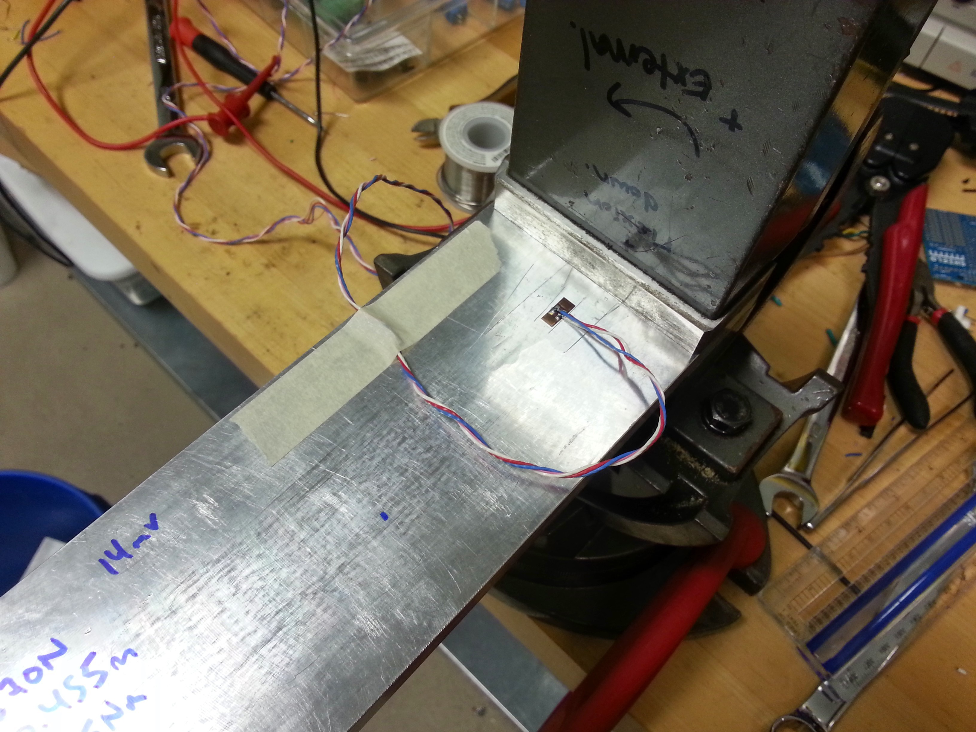
- DONE Source strain gauges
- DONE Optimize installation of strain gauges onto aluminum crank arm
- DONE Source instrumentation amplifier (SOIC package, single supply) and auxiliary components
- DONE Construct prototype instrumentation amplifier (IN-Amp)
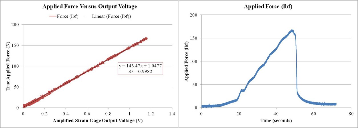
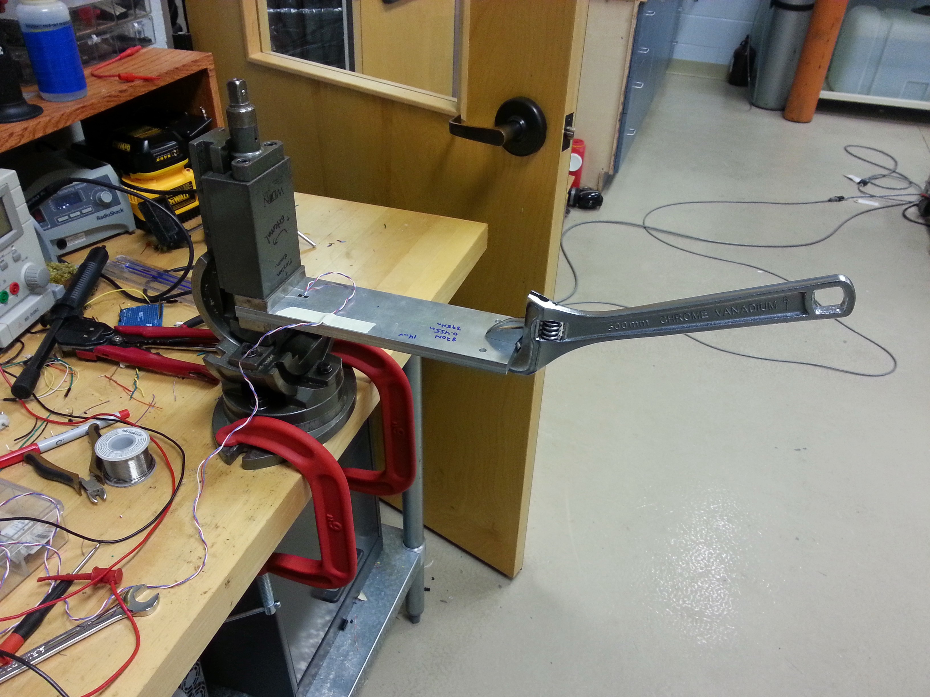
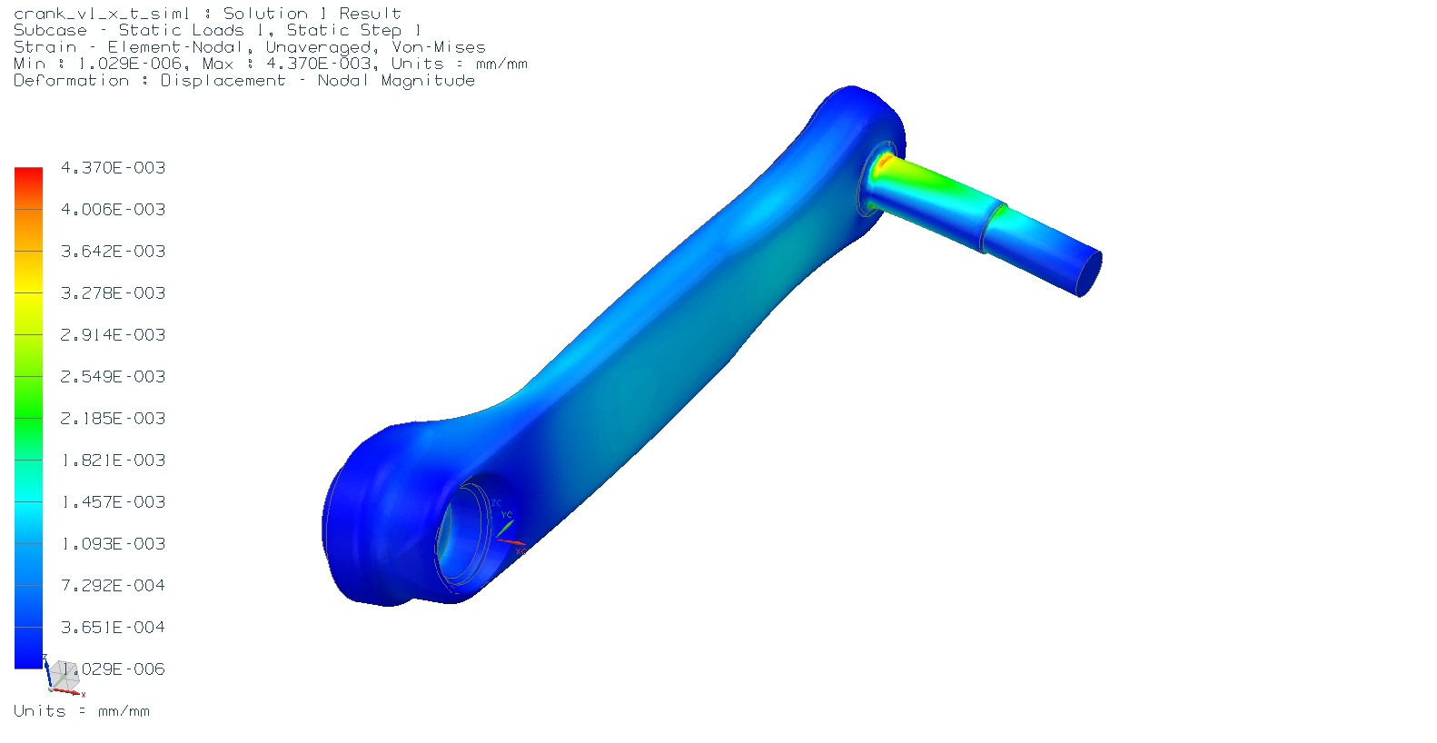
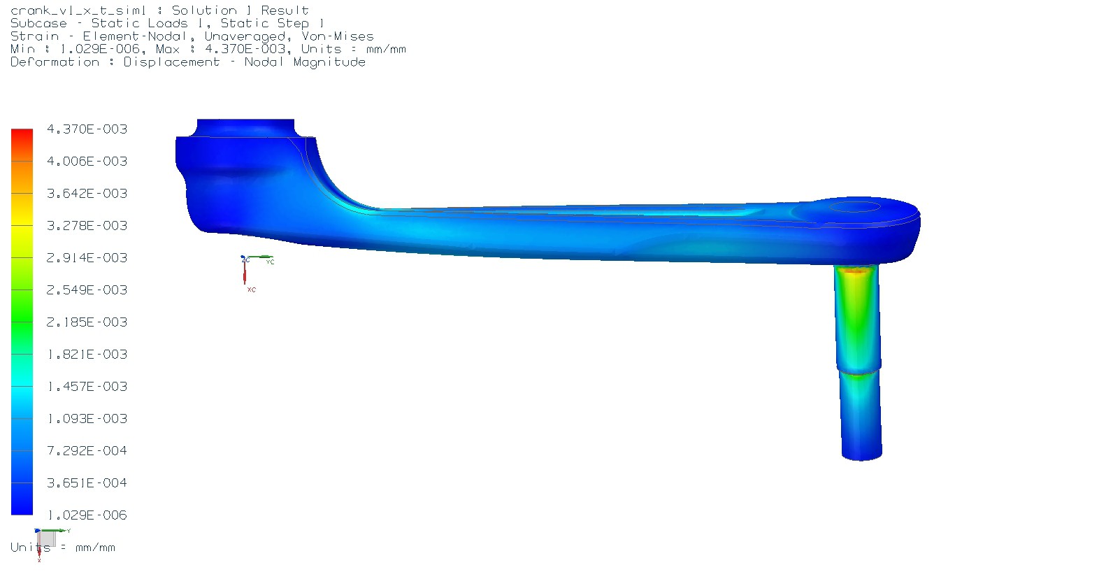
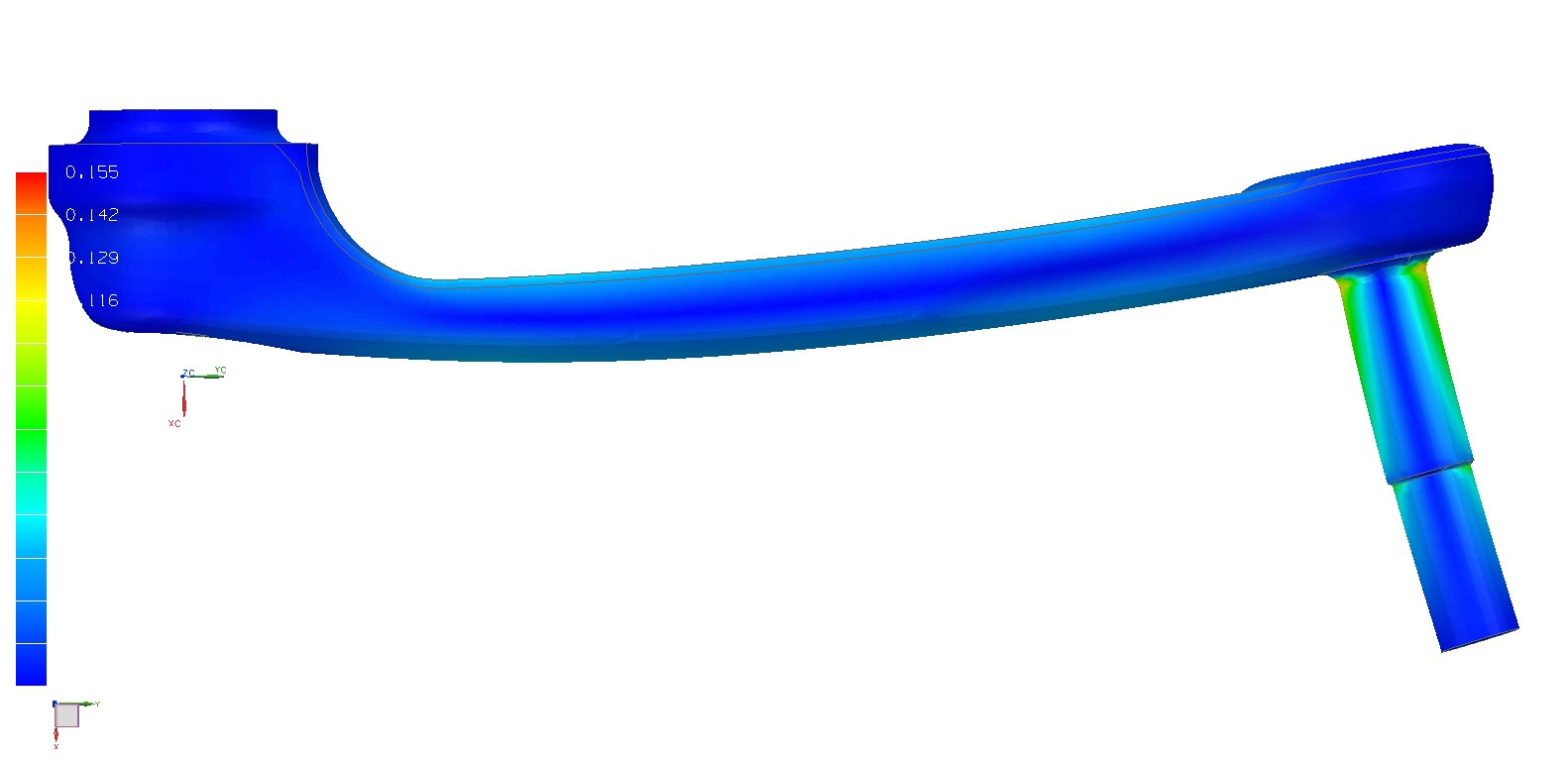
- DONE Perform validation of instrumented crank arm with custom instrumentation using NIST traceable reference (Instron 8872)
- DONE Determine linearity, hysteresis, fatigue life, and sensor crosstalk
- DONE Analysis of the signal will indicate need for filtering (likely need a passive or active LP filter)
Deliverables:
- DONE Strain gauge placement that permits linear (or low hysteresis) over desired measurement range
- SEE PHASE II Battery powered instrumentation amplifier that outputs a 0-5 (or 0-3.3)VDC signal
- DONE 10pt calibration is within specification
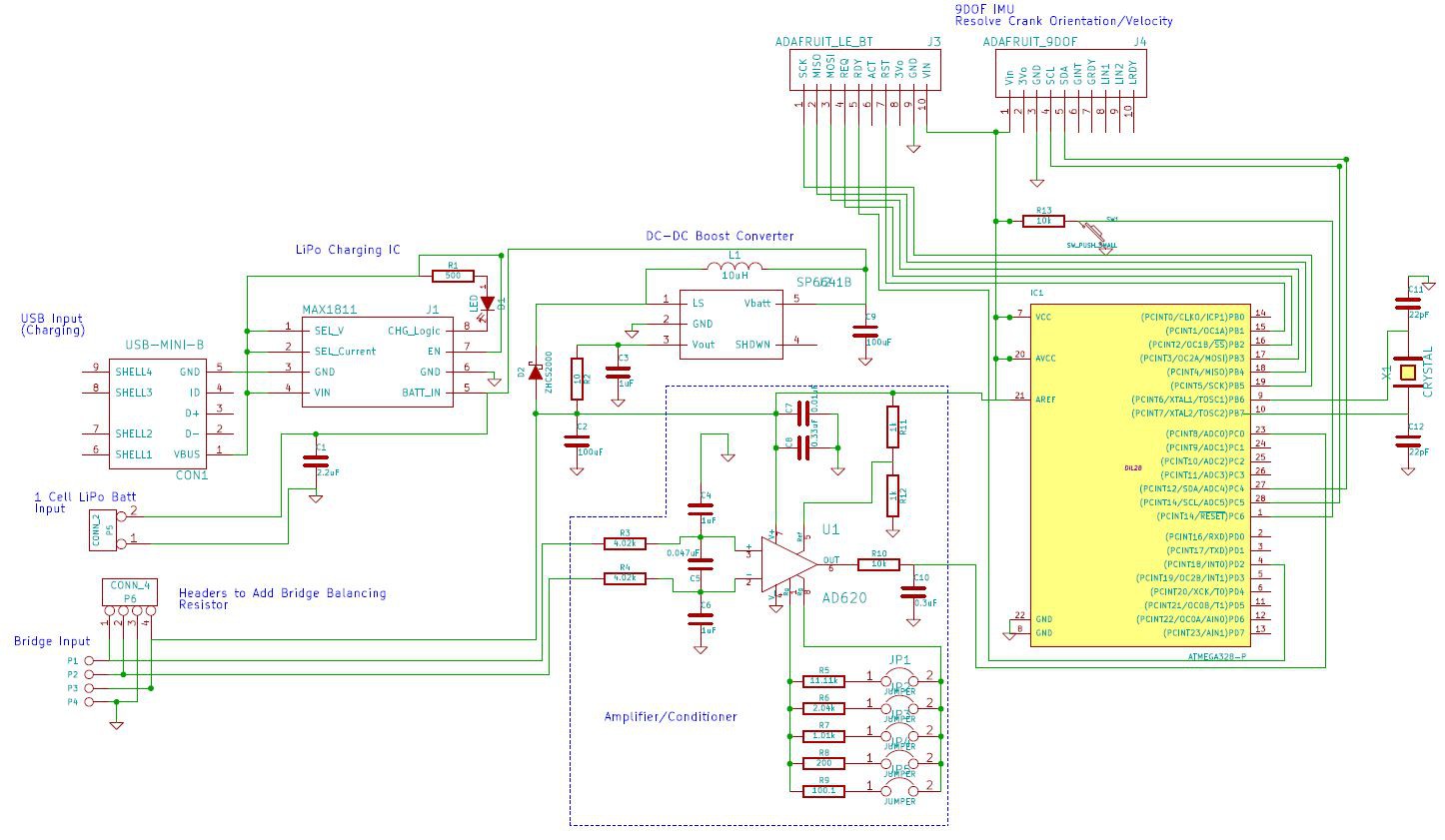
Phase II: Analog Voltage to LE Bluetooth
- DONE Source and microcontroller with ADC and LE bluetooth module that will allow a minimum sampling frequency of 100Hz (in the Android app).
- DONE Source gyro that will be used to determine rotational velocity of crank arm.
- DONE Determine power requirements of circuit so that an appropriate capacity LiPo battery may be chosen
Phase III: Form and Function
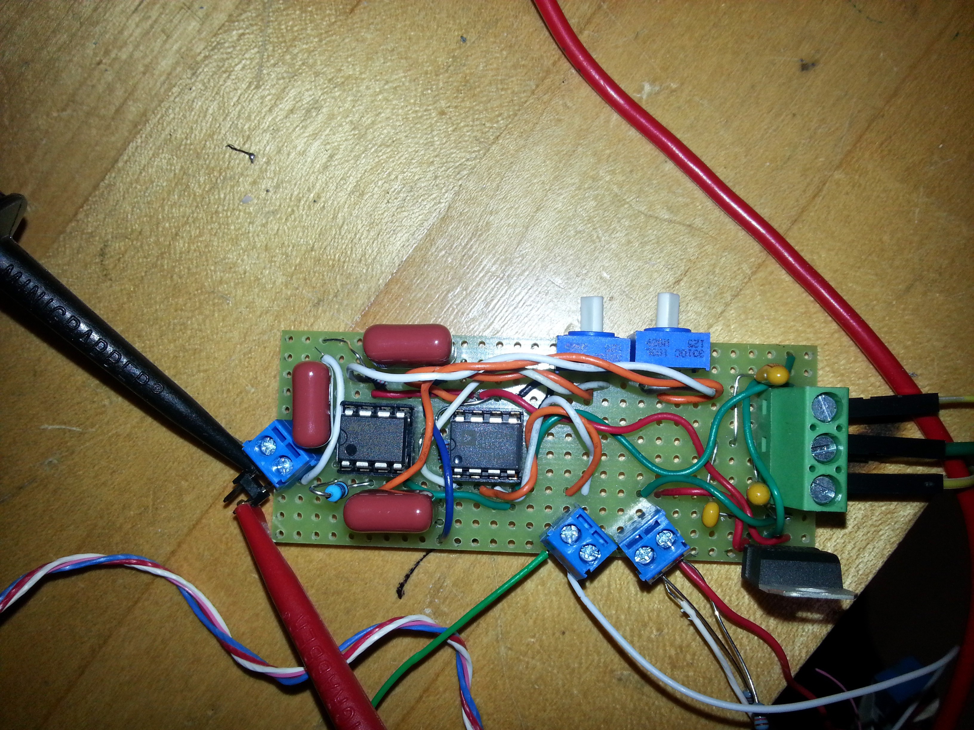
- IN PROGRESS Design custom PCB to integrate all components. No breakout boards (FAILED)...
- NOT STARTED Design custom weather-proof housing
- IN PROGRESS Begin Android application development.
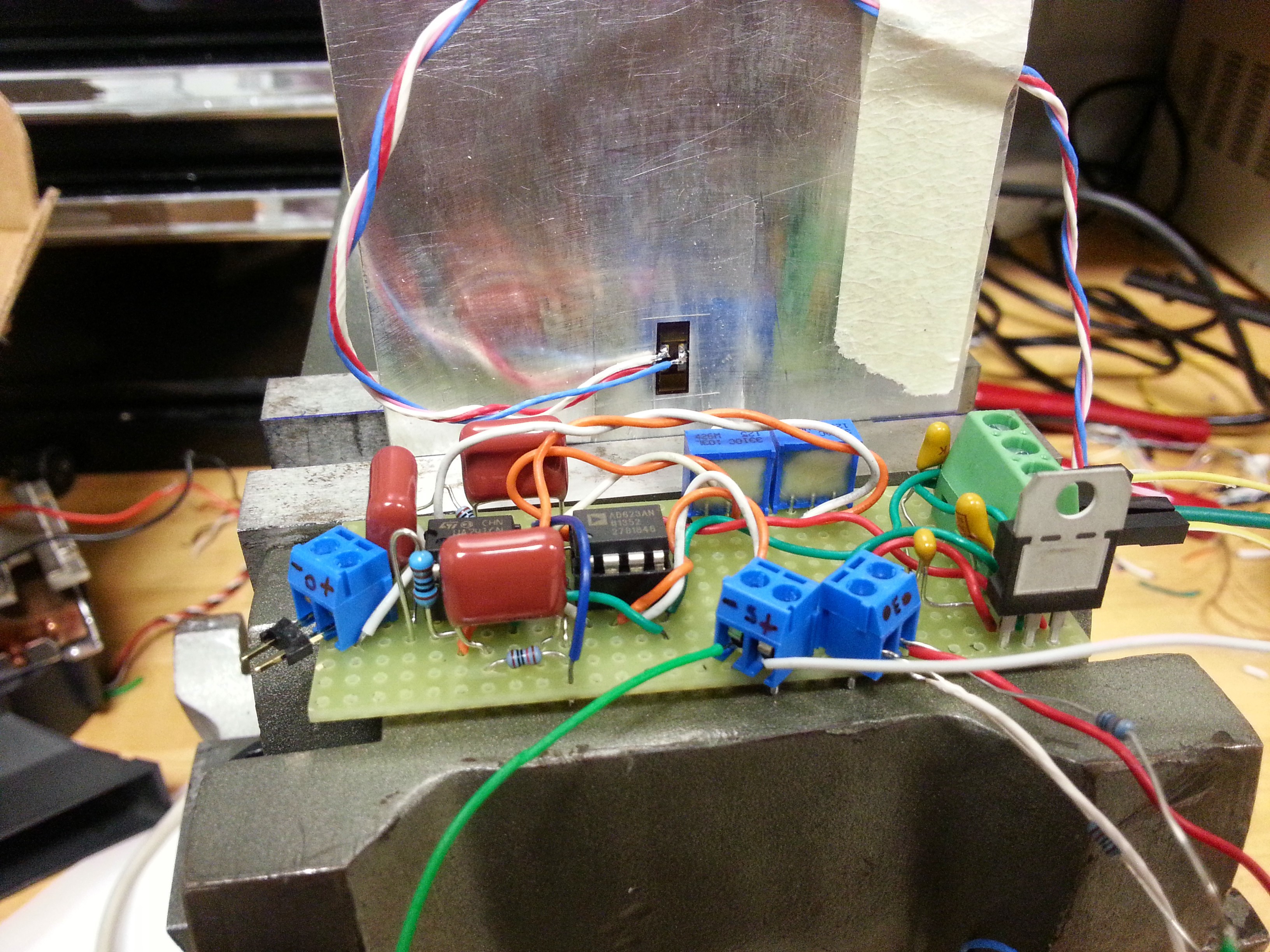
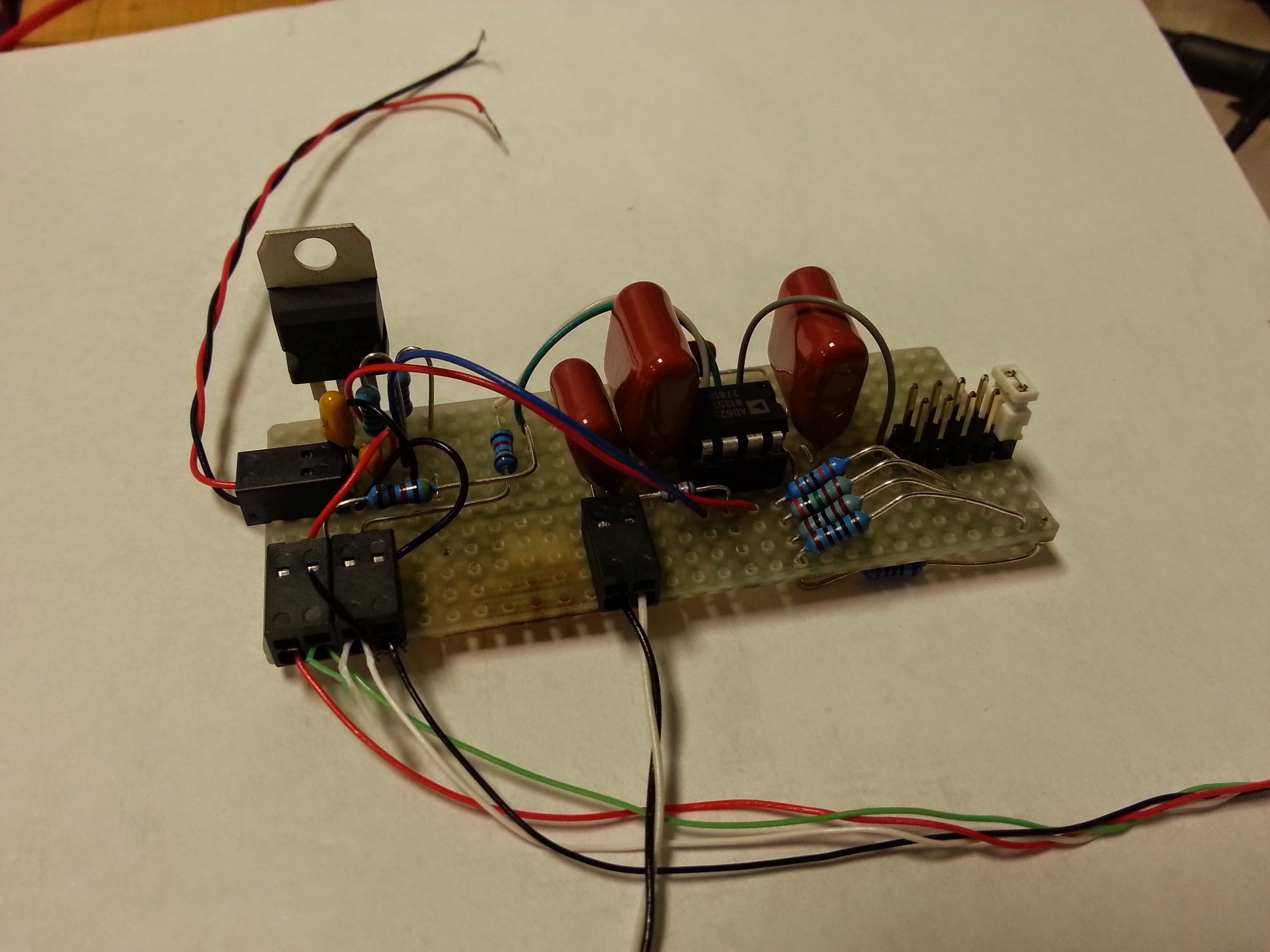 In the photo above, you can see the LM7805 5VDC voltage regulator. In the next prototype, a batter charging circuit, boost converter (to get 5VDC from 3.7VDC LiPo battery), ATmega328, LE bluetooth module, and gyro will be added. The boost converter will replace the inefficient voltage regulator in circuit Rev2, but was suitable for early prototyping and sensor validation. The Analog Device's instrumentation amplifier is top middle, surrounded by polypropylene filtering capacitors. And finally, five 0.1%, 50PPM metal film resistors (one on bottom of board) provide the 5 different gain options depending on the position of the white jumper. This turned out to be a fortuitous design addition, whereby I can easily increase the gain to ridiculous levels to facilitate balancing the bridge, and then quickly change to a lower gain for measurement use. Noise levels were similar to the Rev1 design, approximately 10mV Pk-Pk. As previous results have shown, this is suitable for my purposes, and combined with simple digital filterring techniques, measurement uncertainty is approximately 1-2lbf at 340lbf.
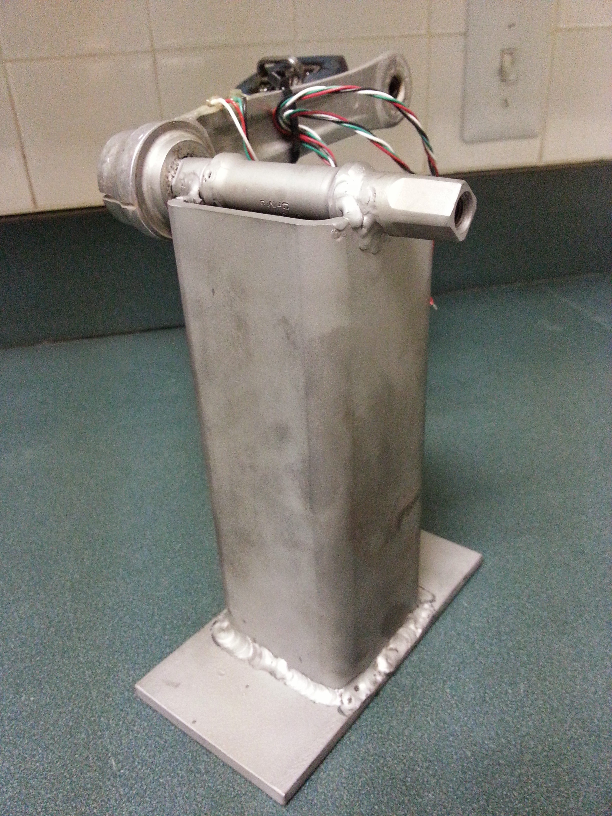

Additionally, grip width is different between snatch and clean so you'd have to re-adjust the gauge (I assume).
There are some training system out there which focus on maximum force/power production, so that'd be a plus. In the snatch, maximum power is typically achieved at less than your max.
Regarding left/right side imbalance: that's typically measured with a force plate under each foot, but measuring at the barbell might just work.
I am wondering if two accelerometers glued to the barbell would just work as well.