-
Circuit; Rev3. Bringing it Together
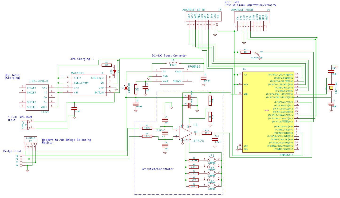
11/02/2014 at 21:51 • 0 commentsAs software development is slow going, I thought I'd spend some time completing the hardware component of the project to improve morale. The plan is to make the circuit (below) as small as possible, 3D print a case, and have a working prototype that I can pass around to collaborators to wrap up the software element. I have located components with SMD footprints for the charging, DC-DC boost, and instrumentation amplifier,
![]()
and plan on getting boards made soon through OSHpark. Incorporating the bluetooth and 9DOF IMU elements are out of my comfort zone, so I'll rely on the Adafruit breakout boards. This is not ideal, but I'm confident that the final device size will be acceptable.
My biggest assumption moving forward is that the 9DOF IMU will provide orientation/rotational velocity feedback accurate enough to meet my requirements. I had planned on using a reed switch on the crank arm to serve as a fiducial for correcting orientation. I will rely on testing to determine if additional input is necessary, or if the 9DOF IMU will be sufficient.
-
Rev2 Circuit Complete
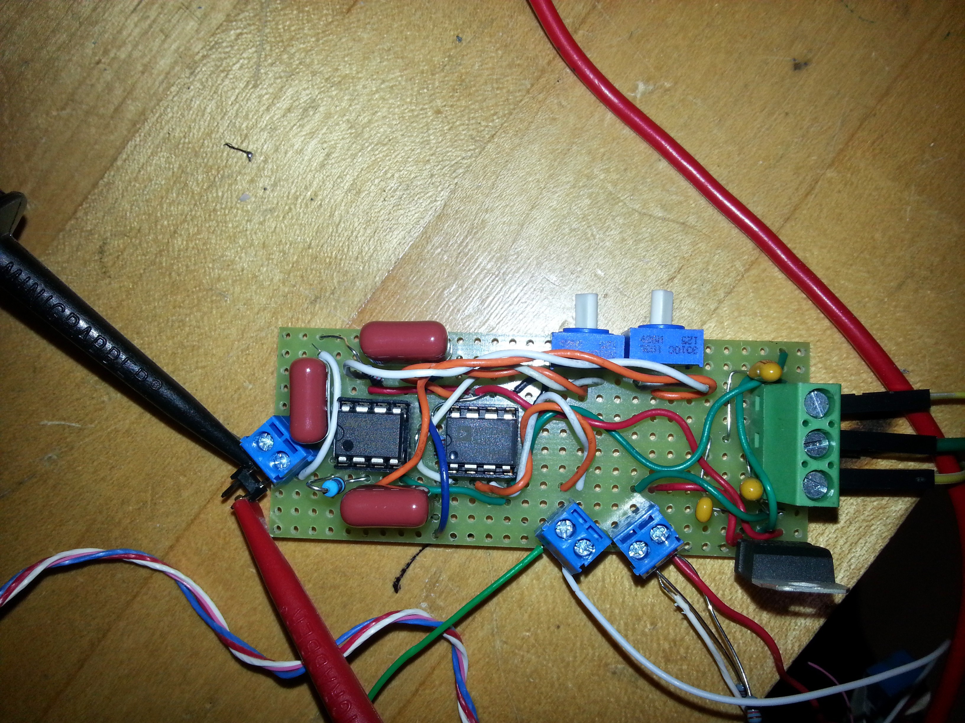
10/18/2014 at 22:07 • 0 commentsThe Rev2 circuit was built and tested [awhile ago]. The design intent was to create a signal conditioner and amplifier for a full wheatstone bridge, single-rail supply (6-18VDC), and jumper settable gain options of 10, 50, 100, 500, and 1000. By design, the output range is 0-5VDC, centered at 2.5VDC. However a potentiometer could easily replace the voltage divider that provides the 2.5VDC reference voltage for the instrumentation amplifier if a different reference is desired.
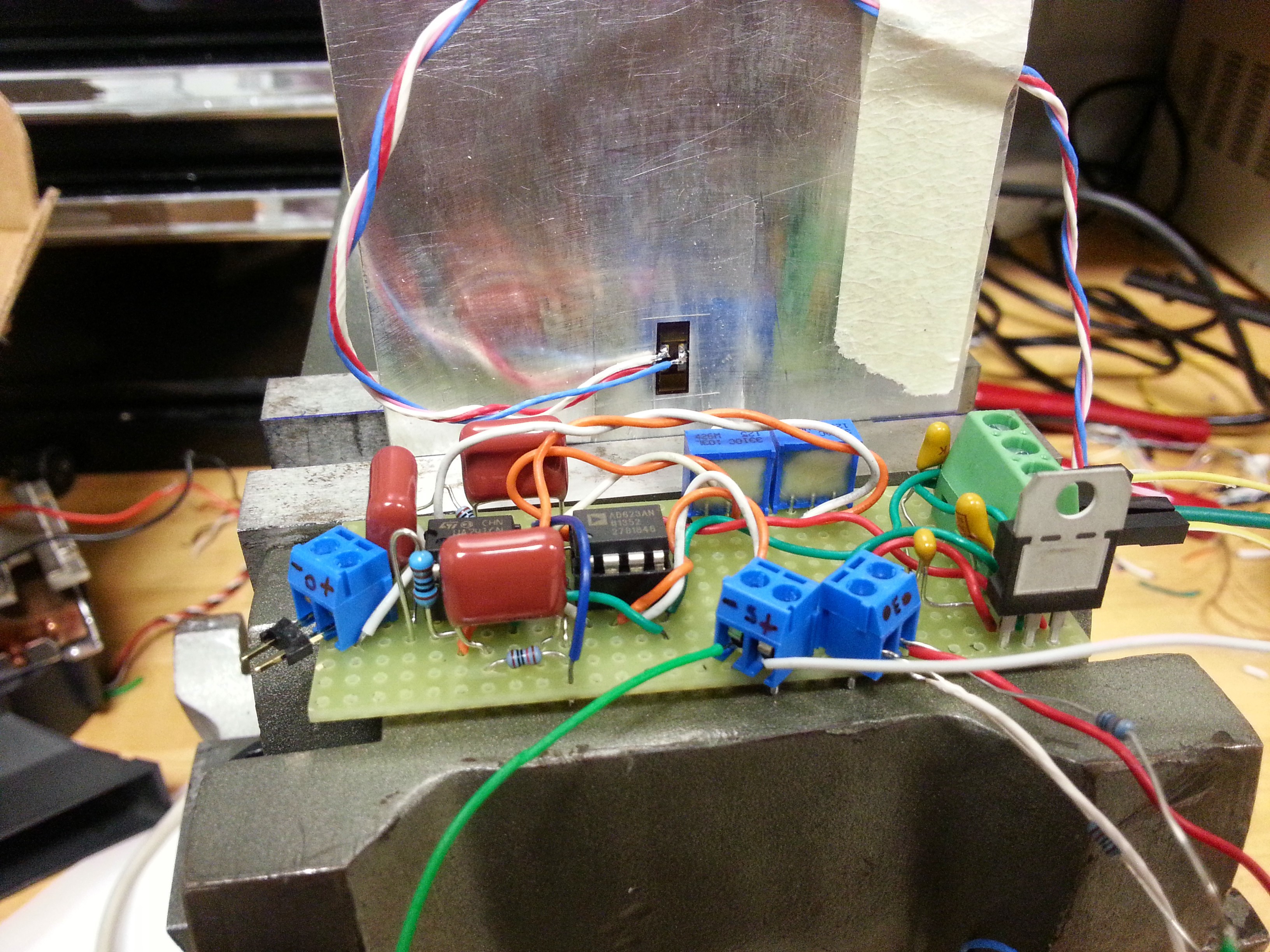
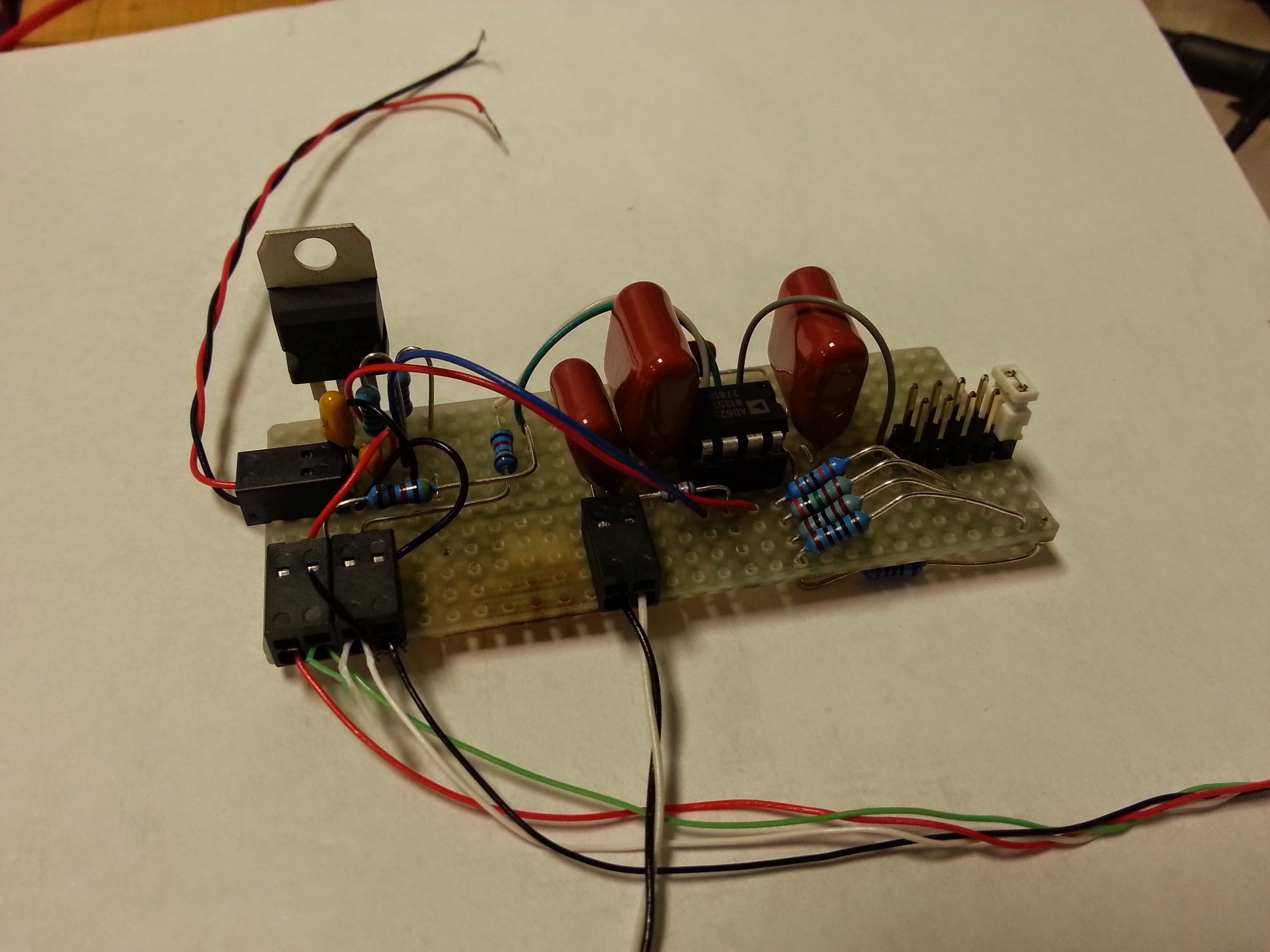
![]() In the photo above, you can see the LM7805 5VDC voltage regulator. In the next prototype, a batter charging circuit, boost converter (to get 5VDC from 3.7VDC LiPo battery), ATmega328, LE bluetooth module, and gyro will be added. The boost converter will replace the inefficient voltage regulator in circuit Rev2, but was suitable for early prototyping and sensor validation. The Analog Device's instrumentation amplifier is top middle, surrounded by polypropylene filtering capacitors. And finally, five 0.1%, 50PPM metal film resistors (one on bottom of board) provide the 5 different gain options depending on the position of the white jumper. This turned out to be a fortuitous design addition, whereby I can easily increase the gain to ridiculous levels to facilitate balancing the bridge, and then quickly change to a lower gain for measurement use. Noise levels were similar to the Rev1 design, approximately 10mV Pk-Pk. As previous results have shown, this is suitable for my purposes, and combined with simple digital filterring techniques, measurement uncertainty is approximately 1-2lbf at 340lbf.
In the photo above, you can see the LM7805 5VDC voltage regulator. In the next prototype, a batter charging circuit, boost converter (to get 5VDC from 3.7VDC LiPo battery), ATmega328, LE bluetooth module, and gyro will be added. The boost converter will replace the inefficient voltage regulator in circuit Rev2, but was suitable for early prototyping and sensor validation. The Analog Device's instrumentation amplifier is top middle, surrounded by polypropylene filtering capacitors. And finally, five 0.1%, 50PPM metal film resistors (one on bottom of board) provide the 5 different gain options depending on the position of the white jumper. This turned out to be a fortuitous design addition, whereby I can easily increase the gain to ridiculous levels to facilitate balancing the bridge, and then quickly change to a lower gain for measurement use. Noise levels were similar to the Rev1 design, approximately 10mV Pk-Pk. As previous results have shown, this is suitable for my purposes, and combined with simple digital filterring techniques, measurement uncertainty is approximately 1-2lbf at 340lbf. Right now the largest hurdle moving forward is developing an Android application that will read the sensor data, and display it in a meaningful way. For prototyping, I purchased a LE bluetooth module (Bluefruit LE - nRF8001 Breakout - v1.0) and will continue working towards this end. If anyone is interested in helping/collaborating, please contact me.
-
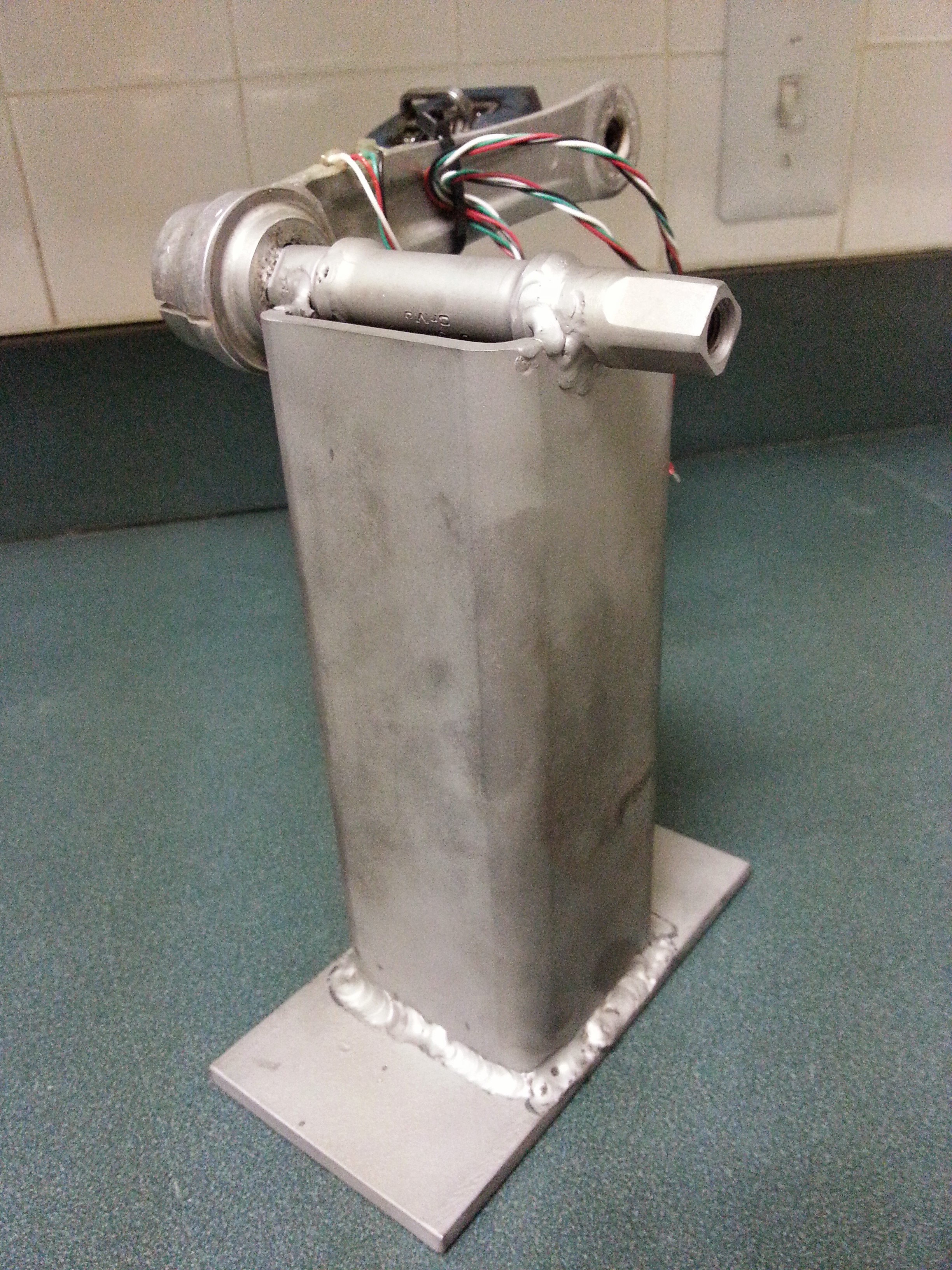
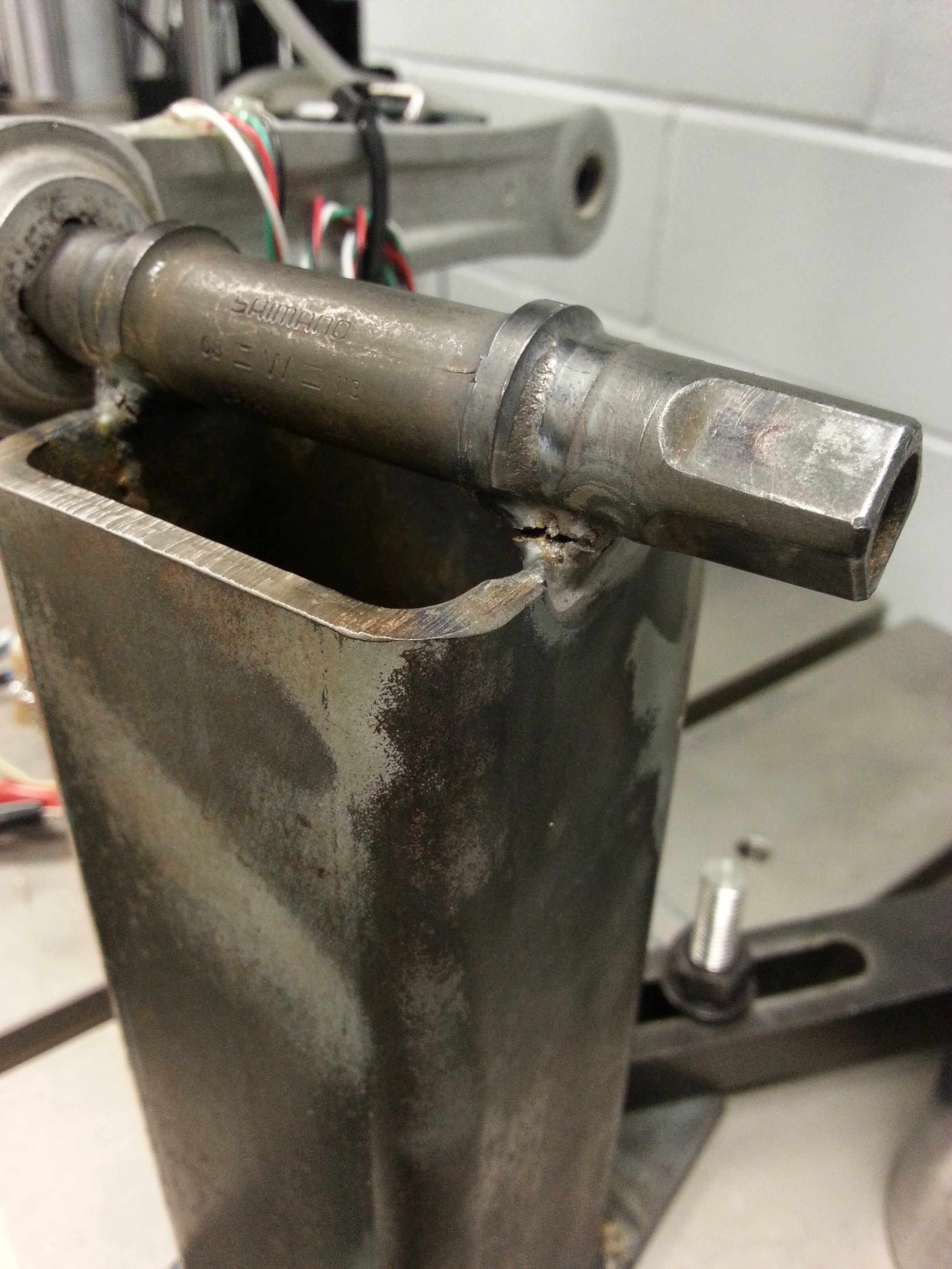
Calibration Fixture Re-Welded
09/29/2014 at 00:50 • 0 commentsRe-welded and sandblasted the calibration fixture. Planning on doing the calibration afterwork 9/29/2014. Also purchased the bluetooth module so that I'll be ready to start coding once the Rev2 circuit is done.
![]()
-
Phase I Almost Complete
09/27/2014 at 02:17 • 0 commentsStrain gage amplifier/conditioner:
The Rev1 amplifier/conditioner circuit was built and tested on both the initial single strain gage test bar, and the fully instrumented crank arm (pictured). The results were very promising, as a gain of approximately 2,500 was used, and the pk-pk fluctuation of the signal was <15mV. Not inconsequential, but in regards to the instrumented crank arm, this amounts to an error of 3lbs (+/- 1.5lbs about mean). The next iteration will move towards a single-side supply, making the circuit much easier to power by a single battery. More importantly, the new revision will provide a 0-5VDC output, with 2.5VDC corresponding to 0% strain. I've abandoned the pursuit to make a device that does not rely on a microcontroller to communicate between the analog-to-digital converter (ADC) and the bluetooth transceiver. Since doing this, it makes component selection much easier, and permits the application of digital signal processing, utilizing a built in ADC, and ability to expand features (scope creep?). The 0-5VDC output signal from the strain gage amplifier/conditioner will be compatible with the microcontroller ADC.
![]()
Instrumenting the crank arm:
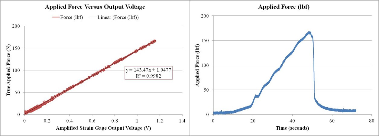
This was much easier than I expected. I had two cranks to instrument, and intentionally instrumented one haphazardly. Ironically, I accidentally tore the leads off of not one, but two strain gages on the one that I spent a lot of time on. However, the 'haphazard' crank worked beautifully. I built a special fixture to allow calibration, and fatigue testing of the strain gages, but sadly I was only able to run one loading run before my welds broke. That is why the applied load curve is non-linear.
I used the same epoxy specified in my previous project log, and it appears to be working, yet I won't know for sure until a proper fatigue test is done (1 million cycles or more).
![]()
Initial calibration:
As previously mentioned, the strain gages were placed 'haphazardly', in that the strain orientation was not aligned along the long axis of the crank arm as well as it could have been. Regardless, the linearity was much better than expected, and the hysteresis was not significant enough to measure (see graph). The error was also independent of the applied load, and fluctuated +/-1.5lbf. This meets my design requirement, but more testing is needed to confirm the result. Due to the premature failure of the calibration fixture, a proper calibration could not be completed (yet).
Another much needed test is to measure the amount of instrument crosstalk. The placement of the gages was designed to measure the applied bending moment and be insensitive to forces applied along the long axis of the crank arm. In essence, if a person is resting on the pedal with the crank resting at bottom-dead-center, there should be no output. Along with the aforementioned fatigue test and hysteresis test, measuring crosstalk will need to be completed before moving forward.
![]()
Path forward:
Order components for Rev2 amplifier/conditioner
Build Rev2 amplifier/conditioner
Re-weld test fixture
Repeat calibration tests
-
Strain Gages Arrived, Much To Do
09/06/2014 at 20:57 • 0 commentsThe strain gages arrived, and initially seem to be okay based on how much the resistance varies from sensor to sensor. The difference ranged from 0.0 ohm to 0.7 ohm, which appear to be on par with more expensive sensors. It doesn't tell the whole story, but so far so good.
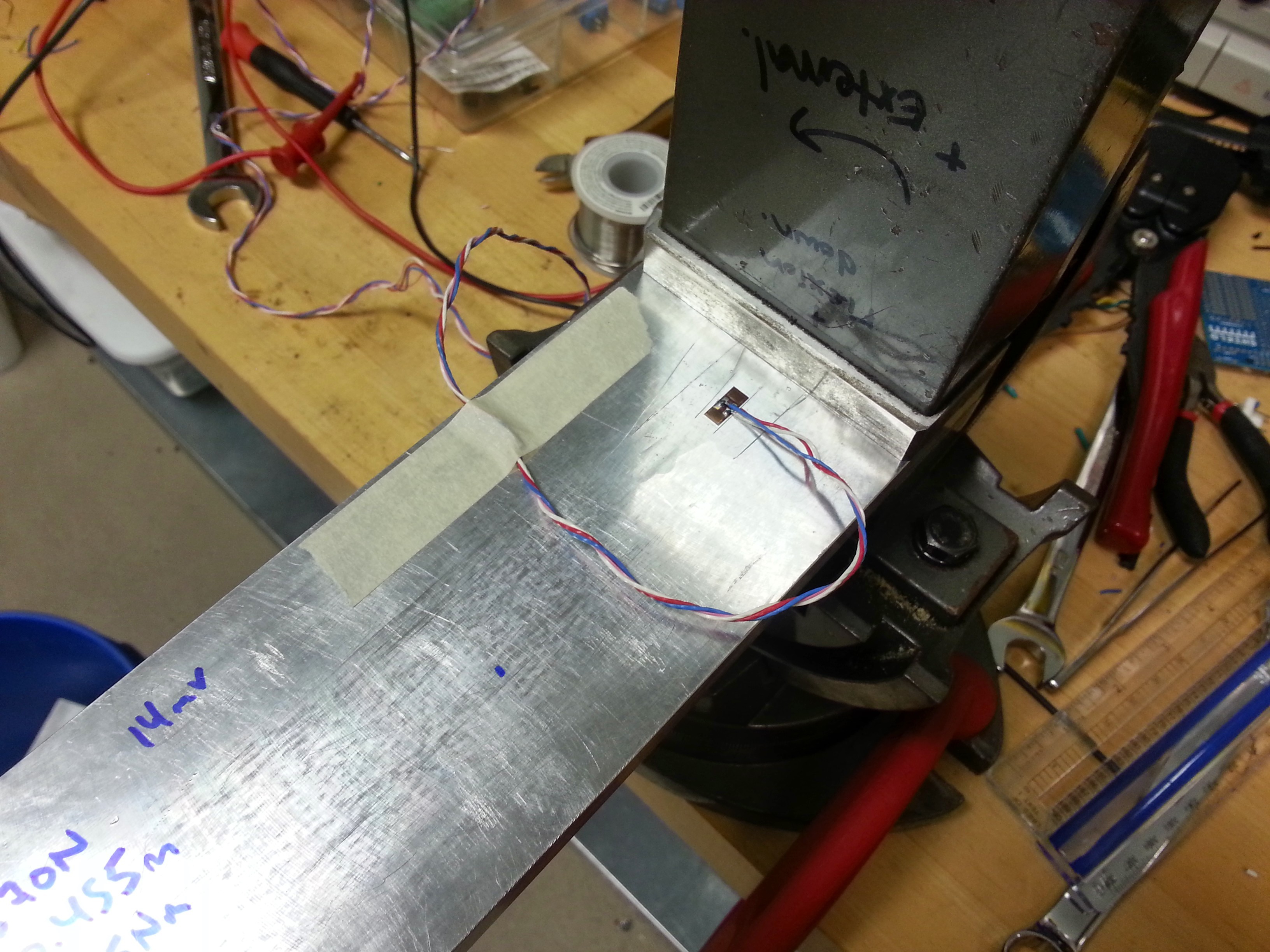
I was researching glue and decided on a high strength (3.5ksi, 24MPa) epoxy I purchased from a home improvement store. I followed some tutorials I found on both Vishay's and Omega Engineering's website as well as on YouTube. After preparing the surface with acetone (to degrease) and isopropyl alcohol (to remove acetone residue), I adhered the strain gage using the tape method and left the epoxy to cure for 24hrs. I then soldered on leads and gave it a shot (see photo).
![]()
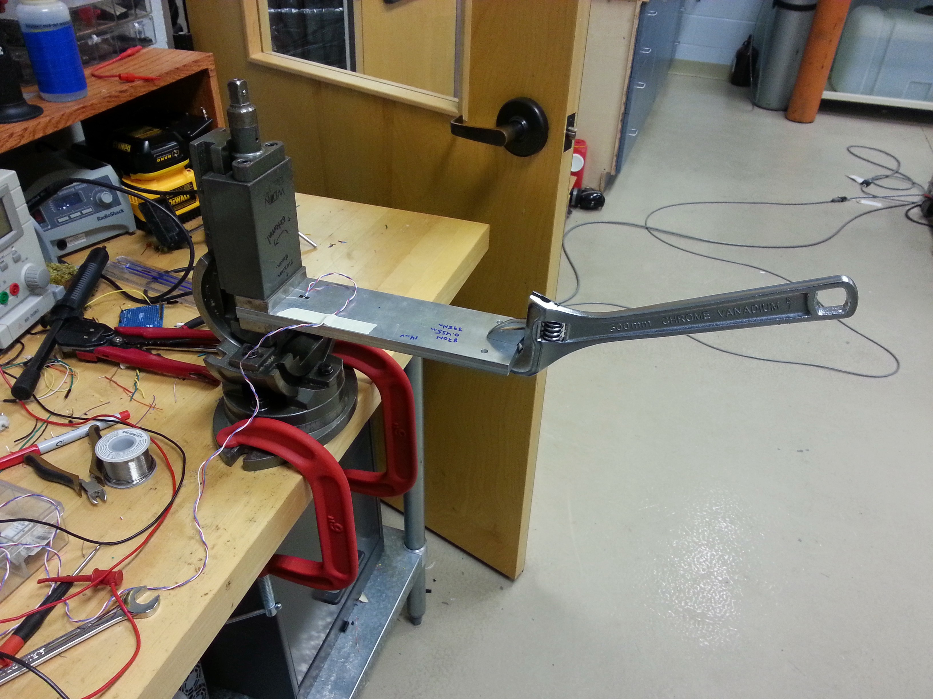
With a variable resistor set to match the resistance of the strain gage, I was able to make a voltage divider with a 10VDC power supply. With approximately 350Nm of bending moment on the beam (see photo), I was able to get a output voltage change of 14mV. Based on this, I estimate that a full bridge will provide ~52mV in practice.
![]()
I designed the first version of the amplifier/conditioner (see photo). It consists of an Analog Devices instrumentation amplifier combined with an active 3rd-order Butterworth filter. There will be a lot of differences between this initial design and the final version, but this will be enough to hash out appropriate gains, noise suppression techniques, and measure the linearity and calibration values of an instrumented crank once it is created (soon). All of the parts have been acquired, so the first version will be made with a standard perf board this week, and hopefully noise levels will be below 2mv pk-pk else a custom PCB will replace the perf. Hopefully it doesn't come to that just yet.
![]()
-
FEA Results- No Strain Gages Yet...
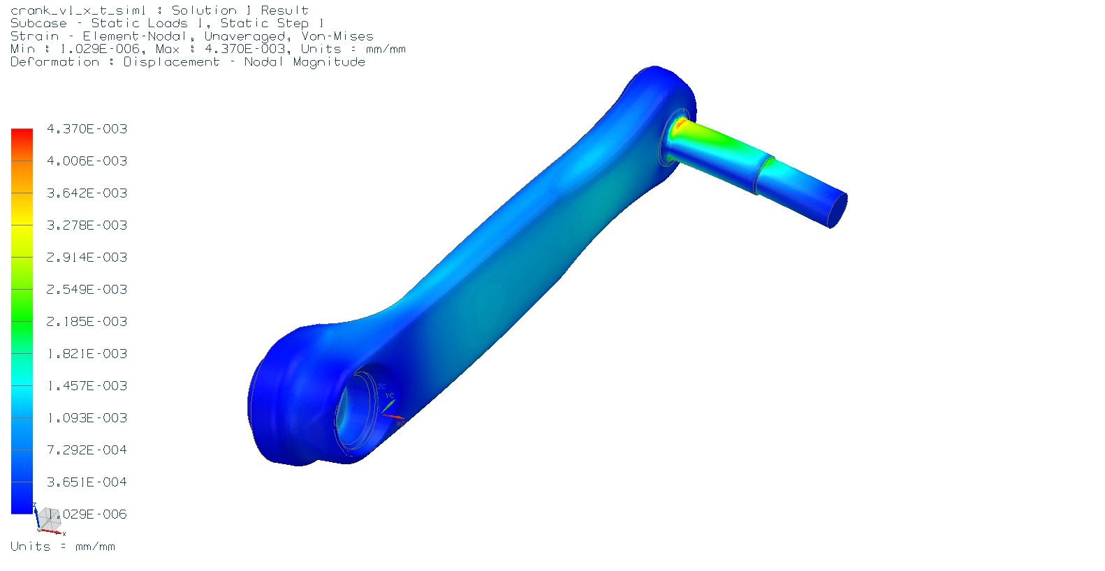
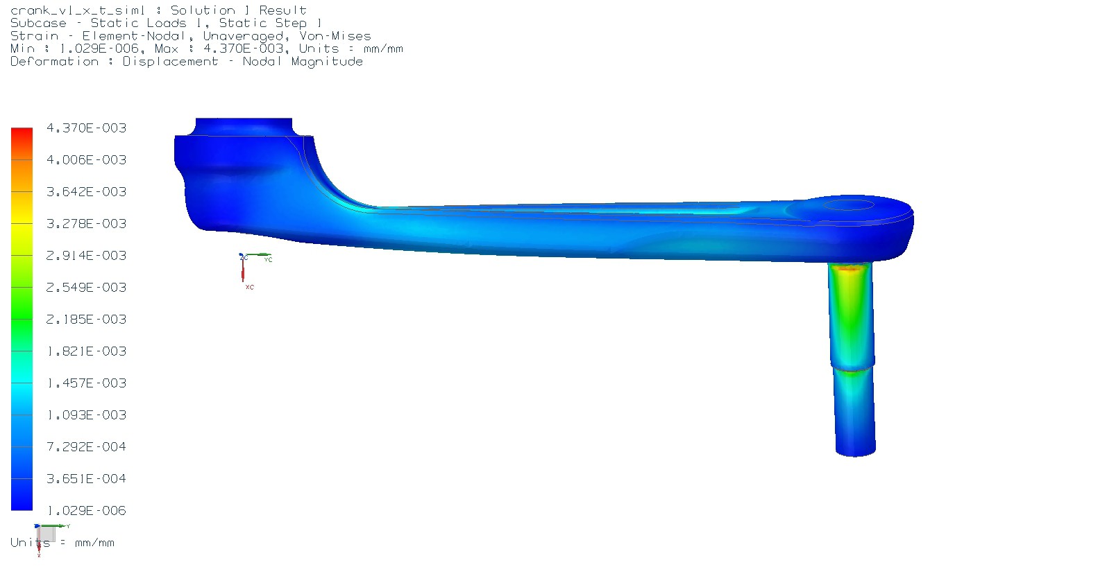
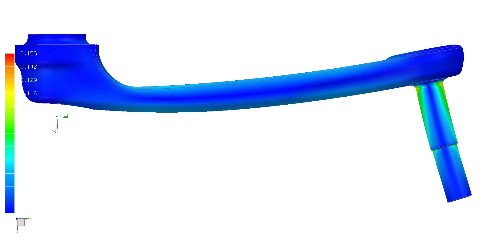
08/31/2014 at 23:12 • 0 commentsStill waiting on the strain gages to swim over from China. As I was waiting, I did some simple FEA on a left crank arm to support my initial strain gage placement. I plan on using 4 gages to create a complete wheatstone bridge that will [hopefully] measure applied bending moments, and yet be insensitive to pure tensile force (when crank is bottom-dead-center and the cyclist is not actively pedaling). The results corroborate the napkin calculations, that strain magnitudes will be far from the gage's 2.5% limit, and therefore ideal placement should be closest to the bottom bracket spindle to increase sensitivity. The FEA results presented were calculated using a 200lbf shear load applied to the end of the "pedal" perpendicular to the long axis of the crank (first and second image), and also with the 200lbf shear load applied parallel to the long axis of the crank (third image, "pure tensile force"). The purpose of the simulation where the force is parallel to the long axis of the crank was to determine how precise/accurate strain gage placement needs to be in order to guarantee that the gages are only sensitive to bending moment, and not a tensile force. Given the region of very low strain along the midline of the crank (third image), it should provide the desired result. Fingers crossed.
![]()
![]()
![]()
Hopefully the strain gages arrive soon, and the trial-and-error process of instrumenting the crank arms can begin. In preparation I'll purchase some hobby-quality 2-part epoxy (Home Depot, Lowes, Ace, etc), and cyanoacrylate + hardener glues. CA glue will be used to adhere the strain gages to the crank arm, while the epoxy will form a protective shield in the inevitable event that I drop it. Note that I'm not purchasing from Omega or the like. Nothing against them, but as cost effectiveness one of my main deliverables, I've decided to take the risk in hopes of finding and demonstrating lower cost alternatives that perform equal to or better than traditional suppliers (Omega, Vishay, etc).
-
Strain Gage Placement II
08/13/2014 at 16:50 • 0 commentsAforementioned napkin calculations suggest that the 2.5% strain afforded by the purchased strain gages is an order of magnitude more than the peak strain induced in a crank given a 2224N pedal load (331Nm equivalent at bottom bracket). I'll still proceed with creating a FEA to provide a more accurate representation of strain three dimensionally. This will take into account the axial torsion due to off-axis loading (pedals aren't in-line with cranks). The lesson learned is that the strain gages should likely be placed as close to the bottom bracket as possible to improve sensitivity.
Purchased 3 crank arms that will arrive this Friday, and will subsequently be instrumented once the strain gages arrive.
Currently designing a test rig that will rigidly hold a crank arm so that the device may be calibrated using an Instron servohydraulic load frame.
While doing some research, Keith Wakeham's previous Hackaday project surfaced. Tremendous amount of work (quality and quantity), yet his blog suggests that work has stopped. It seems a true open source power meter has yet to be created. I think getting away from the usual ANT+ devices (e.g. Garmin) and using smart phones will provide greater flexibility in software design, and allow anyone to produce novel training programs utilizing the power meter. Also I want to do everything possible to avoid using an intermediary microcontroller between the instrumentation amplifier and bluetooth device. This is mainly to reduce power requirements, but also to simplify the circuit, minimize size, and keep component/manufacturing costs low.
-
Strain Gage Placement
08/09/2014 at 01:53 • 0 commentsThe gages are specified as having a max strain threshold of 2.5%. I'll post some estimates for optimal placement on a 6061 Al crank arm (soon to be purchased in triplicates) given a peak applied force of 2000 N. I'll assume the typical cantilevered beam equations are adequate with an elliptical cross-section, and a factor of safety of 2. I'm a little worried this may dilute my low force readings, but I feel it is a good starting point given the risk of sensor delamination or premature failure. Worst, slow sensor drift that would give the appearance of proper function, but entirely wrong. Is that Type 1 error?
By Friday August 15 I should have these calculations done along with a more formal analysis done with NASTRAN. I'll model the cranks as soon as they arrive and run a FEA to guide my first go at sensor placement. Both estimate and analysis will hopefully corroborate each other and be a fun learning opportunity for working with NASTRAN.
-
Sourced Strain Gauges
08/07/2014 at 01:58 • 0 commentsFinally found a cheap source for linear strain gauges. Bought 3 lots (9 gauges per lot) for $37 from DHgate.com. Definitely questionable, but I'm optimistic that they will be sufficient for my purposes. Consistent resistance between gauges will certainly support or discourage my optimism. Will update when they arrive.
Human Power Output Measurement Device For Cycling
A training tool that provides real-time human power output and form feedback
 In the photo above, you can see the LM7805 5VDC voltage regulator. In the next prototype, a batter charging circuit, boost converter (to get 5VDC from 3.7VDC LiPo battery), ATmega328, LE bluetooth module, and gyro will be added. The boost converter will replace the inefficient voltage regulator in circuit Rev2, but was suitable for early prototyping and sensor validation. The Analog Device's instrumentation amplifier is top middle, surrounded by polypropylene filtering capacitors. And finally, five 0.1%, 50PPM metal film resistors (one on bottom of board) provide the 5 different gain options depending on the position of the white jumper. This turned out to be a fortuitous design addition, whereby I can easily increase the gain to ridiculous levels to facilitate balancing the bridge, and then quickly change to a lower gain for measurement use. Noise levels were similar to the Rev1 design, approximately 10mV Pk-Pk. As previous results have shown, this is suitable for my purposes, and combined with simple digital filterring techniques, measurement uncertainty is approximately 1-2lbf at 340lbf.