RPi Telegraph
The 19th century texting device meets the 21st century
The 19th century texting device meets the 21st century
To make the experience fit your profile, pick a username and tell us what interests you.
We found and based on your interests.
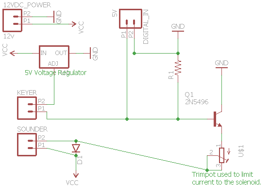
This is my first attempt to capture the schematic using Eagle. I welcome any constructive input on how to improve. I'm using a 12VDC power supply and limiting the current to the sounder using a trimpot. I selected a trimpot so that I can adjust to any sounder since they have varying resistance. I put the Keyer in the same loop as the digital signal so that I can drive the sounder with either an arduino/rpi or with the keyer. I used a 5v voltage regulator to limit the voltage on the bus since it's connected to the microcontroller board. I probably need a diode there, but I have an idea I want to explore, which is to have the wire going to the microcontroller to be used to send commands back to the board.

I've learned (luckily not the hard way) that I need to limit the current going to the solenoids to avoid damaging the sounder. There are a number of references, but I have not yet found a definitive source on what the proper current should be. Each sounder has a known resistance, so I'm going to experiment with a 12VDC Power Supply and will move a way from using the relay shield and replace it with a MOSFET. More to come.
| Power Supply | Sounder | Current Limiting Resistor | Current | Worked? |
| 12V | 20 Ohm | 100 Ohm | 98 mA | Y |
| 12V | 20 Ohm | 150 Ohm | 72 mA | Y |
| 12V | 20 Ohm | 220 Ohm | 50 mA | N |
Create an account to leave a comment. Already have an account? Log In.
Become a member to follow this project and never miss any updates