-
Build update 3 - Mechanical connectors
03/01/2016 at 20:49 • 4 commentsA few months ago I had the idea to create mechanical connectors to be used as building kit for testing circuits before permanently soldering the components, or as a construction toy kit (anyone interested?).
Firstly I choose the right type of terminal: Machine pin header (how they are called?) are perfect because they make good mechanical and electrical connection with the component pluged in.
![]()
I even thought in using a 3D printed mold to create pieces of high temperature silicone to keep the terminal pins from falling apart while soldering them together, but it turns out that it is not so simple, I never had made molds nor worked with silicone casting, and also high resolution 3D printing is expensive. So I started thinking in a cheaper solution using some things that I had laying around.
![]()
![]()
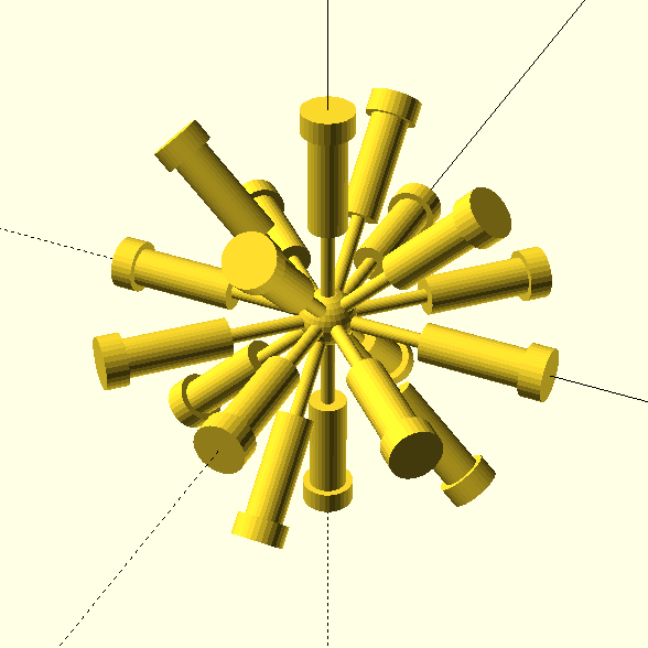
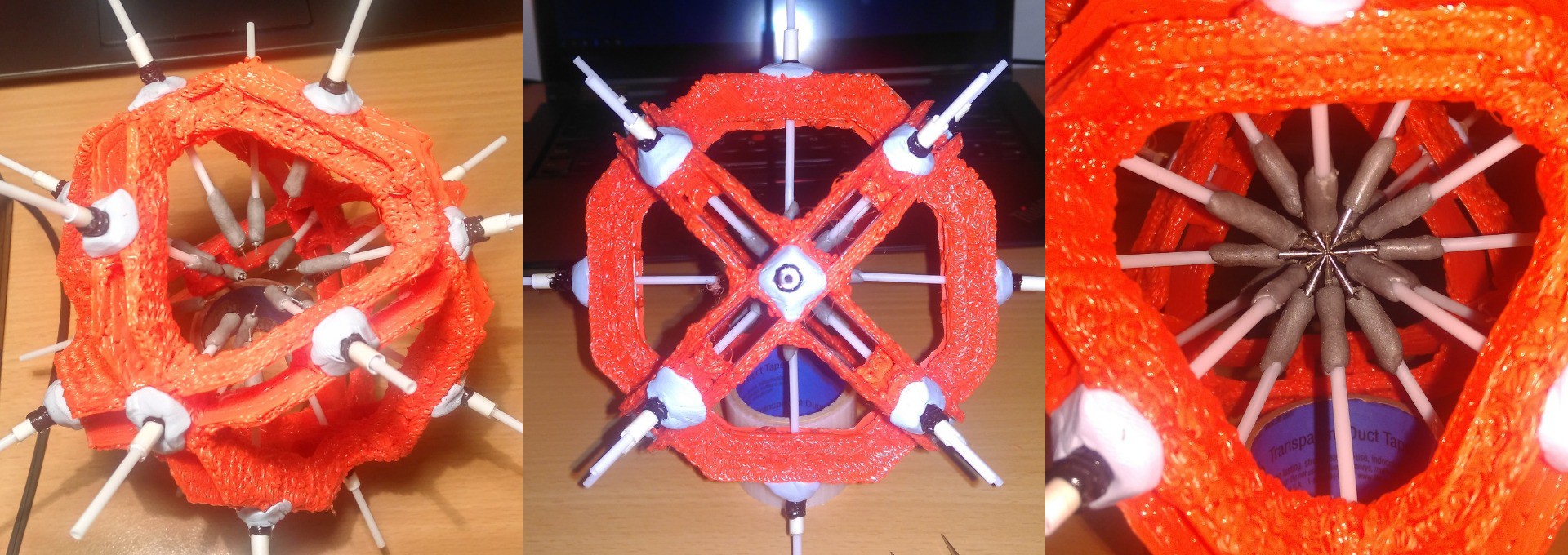
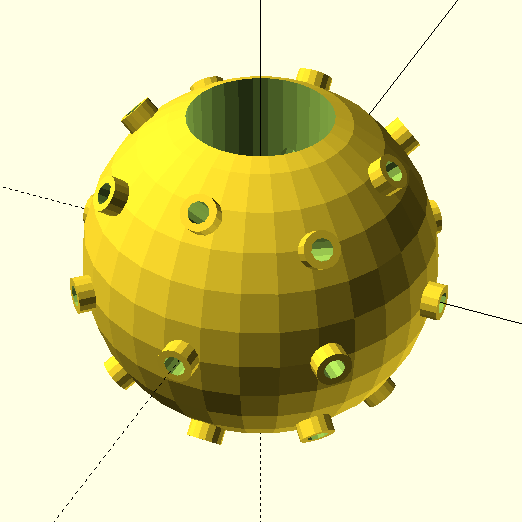
Then I thought in holding the terminal pins in place using some rods, but they had to be keep in place by some kind of structure, at first I conceived a small hollow sphere with some holes to fix the rods, but I remembered that the heat of the soldering iron would melt the structure, so I designed a structure with a shape of a rhombicuboctahedron, but only with the main supports for the rods.
![]()
For the materials, I wanted something mechanically stable, so I buyed 1kg of PLA plastic to use with my 3D drawing pen (I still do not have a 3D printer). It took more than seven hours to manually draw approximately 4 layers of material and join together all the 45 pieces that make the structure. The result was strong enough to kept its shape even when I tried to bend it. I made the holding rods with cotton swab (that will be replaced with some metal rods latter), round female pins, blu-tack, paper, scotch tape and high heat epoxy putty. The blu-tack plays an important role in the apparatus: It made possible to adjust the position and orientation of the rods, compensating the irregularities of the main structure.
![]()
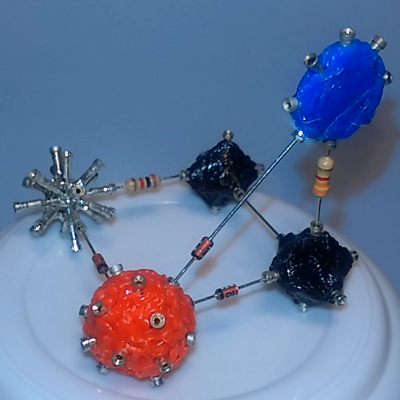
The final build made possible to align all the pins and solder them together to create the custom connectors. I made three types of connectors with the materials that I had in my room:
- Two spherical with 18 connections (one naked and one with red PLA)
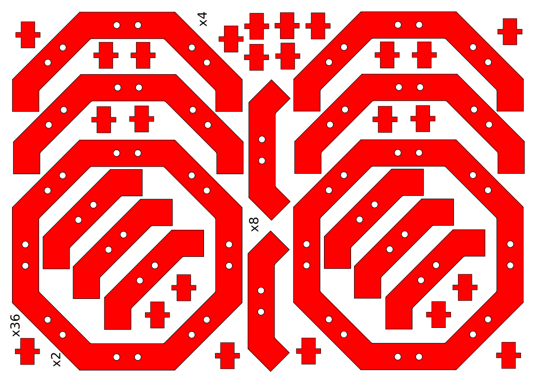
- One octagonal (flat) with 8 connections (blue PLA)
- Two cube-shaped with 6 connections (black PLA)
![]()
The results were great, but I think it still have lots of room for improvements. All fitted together smoothly and produced good quality connections. There is not enough connectors to build some interesting, but I already ordered more headers to start building some more. I will also create some connectors with two and three isolated layers for connecting small two-terminal components and transistors.
![]()
Let me know if you liked the idea, and feel free to give me suggestions! :D
-
Build update 2
02/29/2016 at 07:10 • 0 commentsHey everybody, how are you doing? It is been a few weeks since my last update, since then I put the software development in a halt to focus on thinking about new ways to assemble the volumetric circuits generated by it. If you watched my first project log you can imagine that it is not the easiest way possible to put together the components, back then I used hot glue to fix the first layer of components, and then proceeded to add more layers to the circuit only hoping that the whole thing did not fall apart while melting the solder in the finished connections.
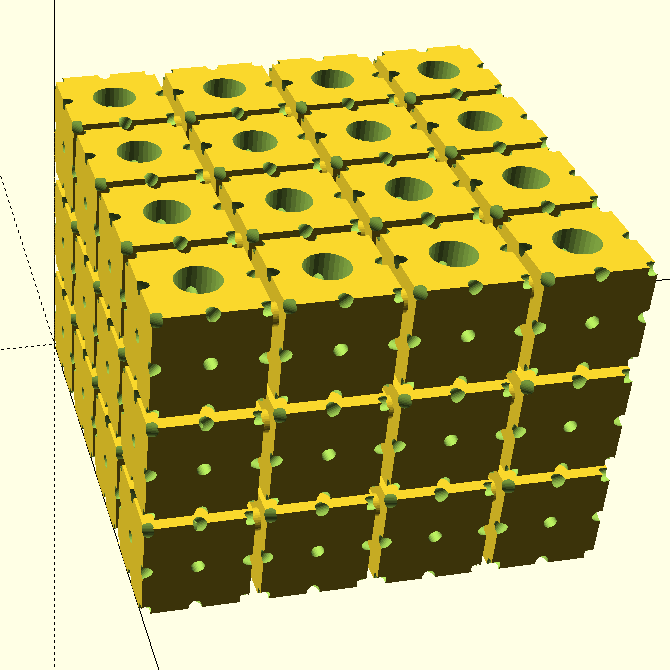
Recently I was examining some alternatives to soldering, like conductive putty, wire glue and others. I wanted to create a easier way to assemble the circuit, so I thought about using 3D printed parts to connect the components together mechanically that have a access hole to allow a drop of a conductive glue to be placed to electrically join them. I also thought in silicone mold casting, but after some iterations on the design and some price estimations I did not thought that it will be viable, yet.
![]()
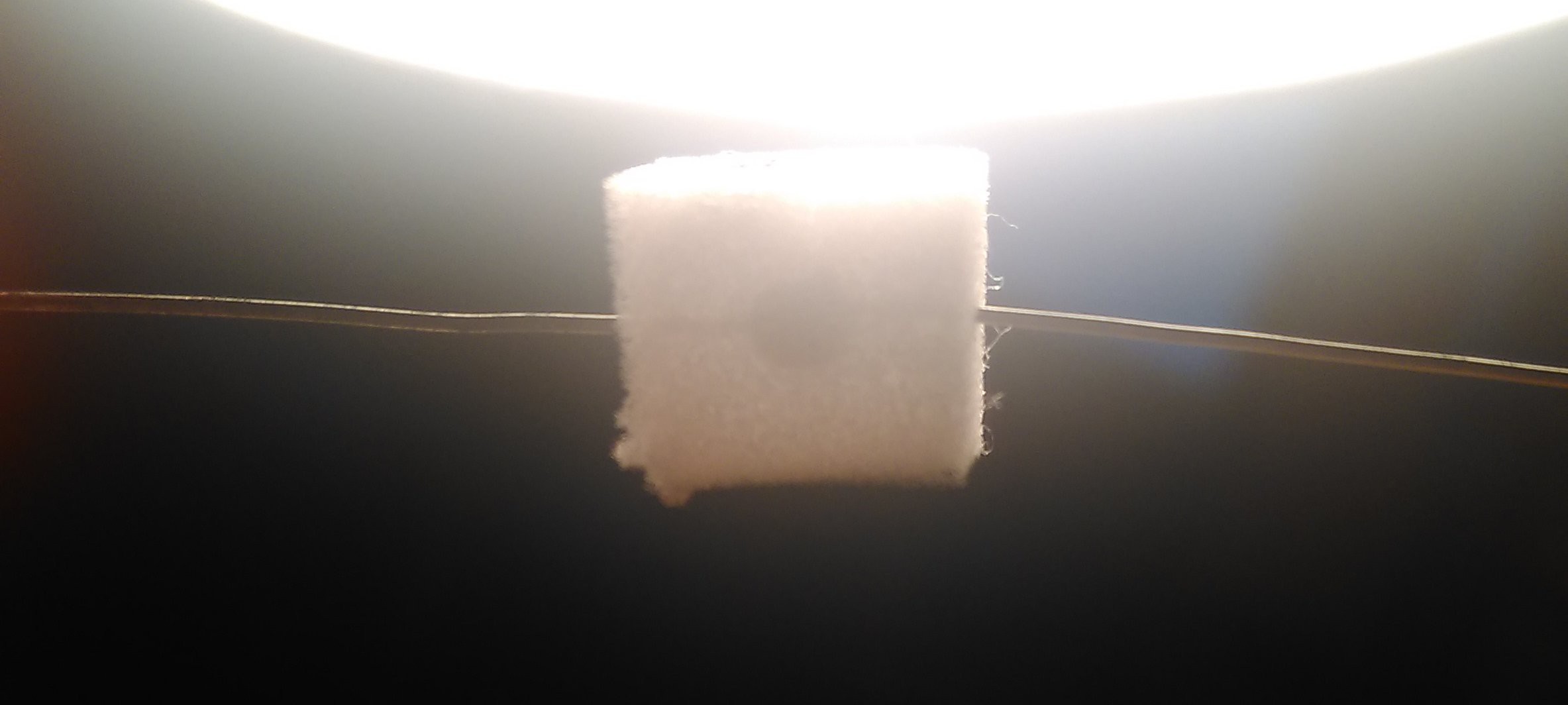
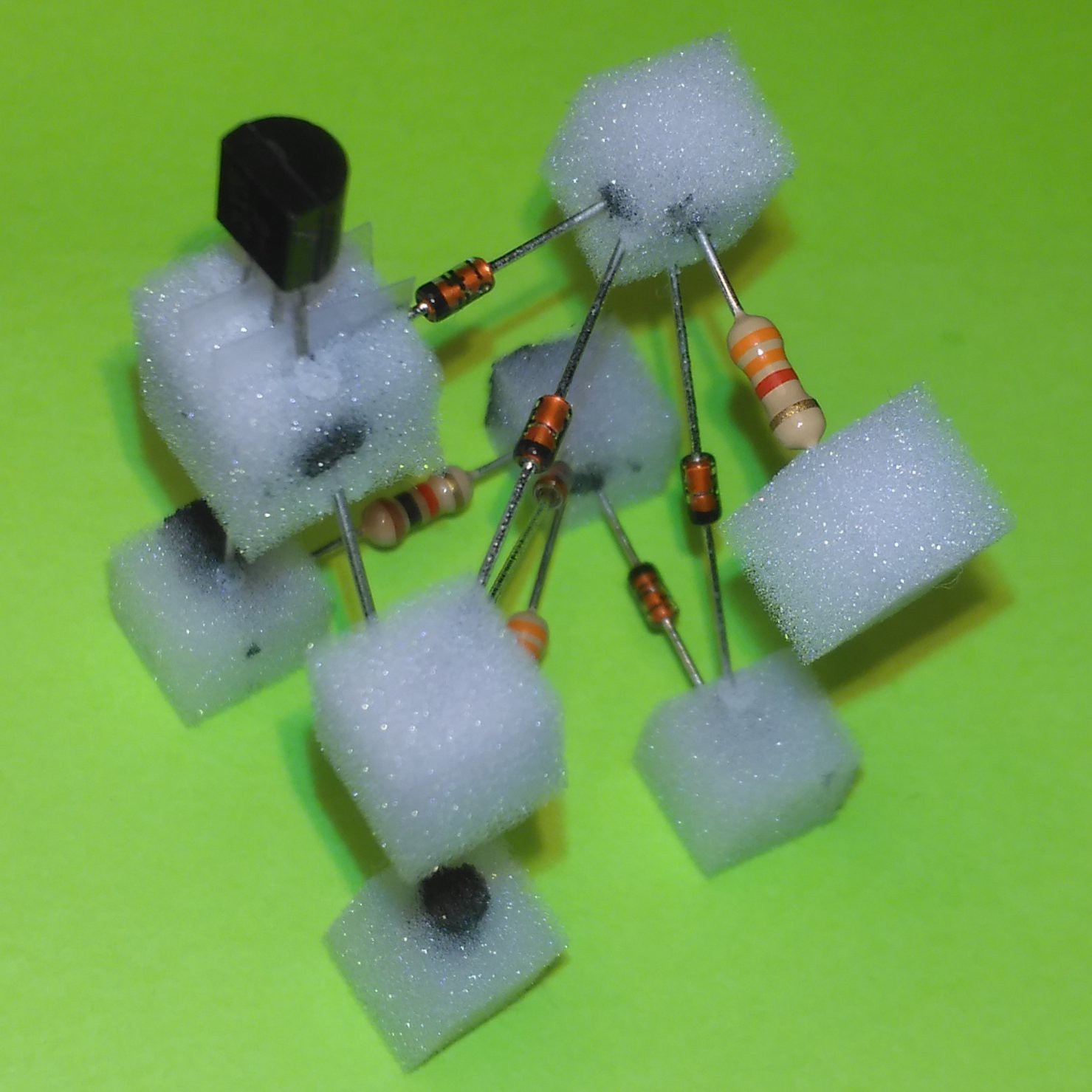
![]() I tried a cheap alternative to the 3D printed parts: Melamine foam (magic sponge), due its density and stability. I assembled the circuit together and used a syringe with a needle to inject some wire glue in the sponge cubes.
I tried a cheap alternative to the 3D printed parts: Melamine foam (magic sponge), due its density and stability. I assembled the circuit together and used a syringe with a needle to inject some wire glue in the sponge cubes.![]()
The results showed a higher electrical resistance than expected in the connections (sometimes higher than one kilo Ohm), and a fragile structure, but I think that the technique can be further improved.
![]()
-
Pyrite demo download
01/27/2016 at 06:30 • 2 commentsIf you want to play a little bit with the pre-alpha software go ahead! Pyrite is now for download!!
I still feel that there are a lot of things to do but I think that I am making some progress! Hope that you enjoy, the user interface is very raw but it is fun to see the circuit in 3D and move around :D
This version should run on Linux, Mac OS X and Windows, but unfortunately I can only help you if you are using Linux.
Instructions:
- Extract the contents of the zip file
- Run Pyrite using
java -jar Pyrite.jar - Open the demo project file
Demo.proj - Double click the file
Volumetric Circuit - Click the
foldbutton on the floating window - Have fun!
1. You can create your own circuit files and attach them as "resources" to new volumetric circuit files, but each time that you edit your circuit file you have to restart the software. If you want I can make a screen recording, just ask.
2. The folding algorithm is not finished yet, this is only the first steps, it is a great improvement since the first version, I was focused in reducing the number of added nodes, so now I have to improve the density of the final volumetric circuit. I am planning to release new algorithm sections (steps/phases) on version v0.9.4, along with new ways for people to improve/contribute code for the folding process.
Remember that this is a pre-alpha demo, there are still a lot of things to fix and to improve.
"Planning":
- v0.9.3 better GUI
- v0.9.4 better folding algorithm / custom algorithms
- v0.9.5 blueprint generator
- v0.9.6 code cleanup, proper developer documentation and wiki
Download here: https://github.com/anderson-/Pyrite/releases/tag/0.9.2
-
New Folding Algorithm - Update #1
12/29/2015 at 18:10 • 0 commentsIt is been a while, but here it is, a quick overview on the current state of the software (watch with the annotations turn on):Hope that you guys liked :)
There are still a lot of things that still need to be integrated to the algorithm before it could be released, e.g., it does not work for graphs that have node with more than 26 connections, think about the common ground node in bigger circuits. In the following weeks I'll try to commit some changes to GitHub and release an alpha version.
-
A new project log, finally!
12/01/2015 at 15:23 • 1 commentHey guys, it’s been a very long long long time since the last update, I was very unmotivated about rebuilding all the core 3D drawing program in OpenGL, even having a few exciting new ideas to test.
In the beginning my algorithm was placing most of the nodes following a pattern and then trying to solve the remaining connections by placing a huge amount of new empty nodes (without components), using this strategy probably I never will be able to get a good solution.
The new idea that I had back then was to evolve the 3D shape of the graph using a force-driven drawing algorithm, in this way we could start fitting the graph to our chosen 3D lattice pattern (the grid). I searched for some project that could draw graphs in 3D and I found one promising project by [Mark] (aka pachacamac in GitHub) called jg3d (https://github.com/pachacamac/jg3d), I played with it for some time and ended up adding it to Pyrite as a module called Newton (https://github.com/anderson-/Newton). It was a good tool to visualize the graphs and faster and much more reliable than the current one based on Processing.
So a few months ago I started to improve the user interface of jg3d to fit better the purpose of folding graphs just for fun, only manually this time. Then I realize that using OpenGL was the way to go and started to develop a new monitor using LWJGL. After this I ended up creating a new graph folder from scratch only to test some algorithms. I had to move from LWJGL to JOGL because I wanted to be able to have multiple OpenGL panels and also swing integration.
After tuning the new algorithms I finally could fold a graph (36 nodes and 74 edges) with up to 97% of satisfied connections without adding any new nodes, something that I found really remarkable if you look back to the beginning of the project. Now I still have a plenty of tests to do and new ideas to try, I’ll try to keep you guys updated. I still have to clean up the code, add it to Pyrite but I plan to release a major update in a month or so.
This week I’ll post a new video showing the progress that I made, but if you can’t wait here is a preview of one run of the programThe red edges of the graph turn green when it connection is satisfied (is fitted to the lattice/grid). Sorry for the spinning speed and the poor quality... The next video will be better.
-
New placing algorithm & OpenGL help needed
10/02/2014 at 03:53 • 0 commentsHi guys, I've been very busy with college lately but I got a few updates to show.
First of all, the project was featured on Hackaday! I would like to thank the great feedback from the Hackaday community, It really means a lot to me!
Recently I implemented some new functions on Pyrite (not committed yet), the first is a new method of placing components in the grid. The idea was to find cycles in the circuit graph and try to position then perpendicular to each other before routing.
![]()
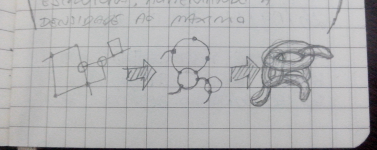
I'm trying to place all components in a circle before routing. Currently the cycle can only be placed in the shape of a rectangle, in latter versions will be possible not only to chose the cycle shape, but "fold" the shape so maximum density can be achieved.
The current algorithm find some random cycles and them selects one to place. The results look promising:
![]()
I also start implementing an boundary editor for creating delimited circuits:
![]()
Processing vs pure JOGL
Currently Pyrite uses Processing for drawing 3D graphics, the problem is that Processing can only run one instance at a time, it sometimes fail to load on Swing panels and it is sometimes slow. So I looking for alternatives. I wold like to use only JOGL, I only need 3 things:
- Drawing simple shapes and lines
- Moving around easily (Camera)
- Picking objects (color picking probably)
I found really hard to find some alternative and developing this all by myself with 0 knowledge of OpenGL has showed to be a hard task, so if you know OpenGL and like to help, let me know!
-
Full ALU simulation on Pyrite
08/20/2014 at 17:22 • 0 commentsThe ALU design is done, now is time to test it. I put the schematics into the simulator and after some debugging it was ready to run, the result was great, all worked as expected. The following gif shows the schematics and demonstrate the simulator modularity concept.
![]()
Here is the ALU performing some random operations:
![]()
-
ALU designed!
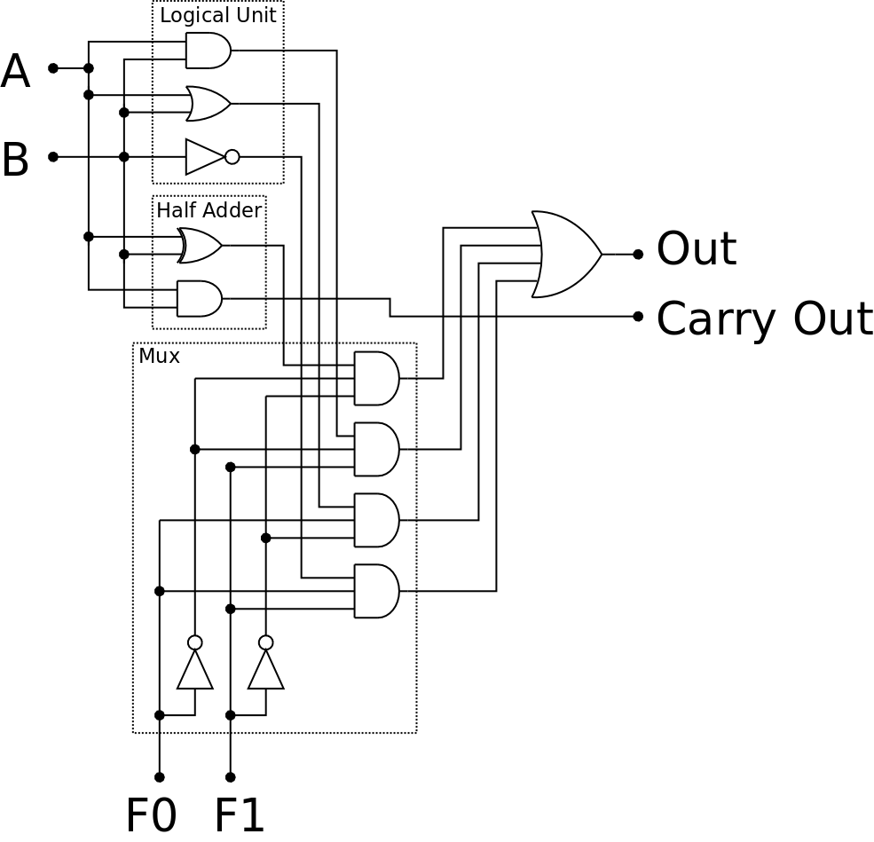
08/20/2014 at 02:00 • 0 commentsThe finished the ALU design allows it perform the following operations: AND, OR, invert B, and SUM. I tried to keep the things simple, so I put an half adder instead an full adder.
The next step is gonna be simulating the whole thing in the last version of Pyrite.
![]()
-
Software update – Pyrite alpha
08/19/2014 at 04:09 • 0 commentsI'm pre-releasing the alpha version of Pyrite, I'm still need to finish the GUI, fix some bugs and optimize the graph algorithms, there is a lot of work to do but will be nice to hear some comments about the software, so be free to look this unfinished build.
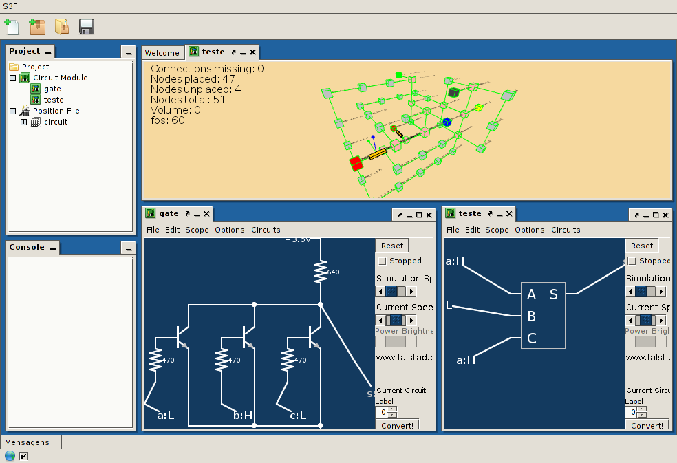
This version uses a framework that I'm developing in the last months (S3F - https://github.com/anderson-/S3F, page in Portuguese, sorry) and includes an modified Paul Falstad's circuit simulator (www.falstad.com/circuit) as the default schematic editor. It can now run several simulations independently, and have a new component for allowing modularity (sub-circuits).
The next step is defining the ALU design, simulating it, and create the 3D schematic.
![]()
Download (linux): https://github.com/anderson-/Pyrite/releases
![]()
2D Schematic editor shortcuts:
“;” - place sub-circuit (right-click->edit, for choosing the circuit);
“+” - place logic input;
“-” - place logic output;
3D schematic editor shortcuts:
“1” -> “5” - change grid;
“r” - place source and ground in positions {4, 2, 2} and {2, 2, 2}, respectively;
“ENTER” - start fitting alghorithm;
-
First prototype! :D
08/13/2014 at 04:18 • 0 commentsThis is my first prototype using an alpha version of the software: Building an diode-transistor XOR gate. All the algorithms performed accordingly, the gate schematic was fine, but I wanted to place push buttons as inputs and an LED as output, and ended messing all up... But for the first test it was great! :D Here is an video of the process:
Note: In the video I clicked in a button called "load" while working with the software, it loaded an previously edited position file for the nodes, basically I jumped one step in the process: The adjust of the automatic placed graph, in the "time-lapse" I'm only verifying the output graph, it was correct.
Volumetric Circuits!
A schematic editor for "3D discrete grid-aligned circuits" and building a 1-bit ALU
 Anderson Antunes


 I tried a cheap alternative to the 3D printed parts: Melamine foam (magic sponge), due its density and stability. I assembled the circuit together and used a syringe with a needle to inject some wire glue in the sponge cubes.