SUF
SUF-
Theory of operation: RPM Measurement
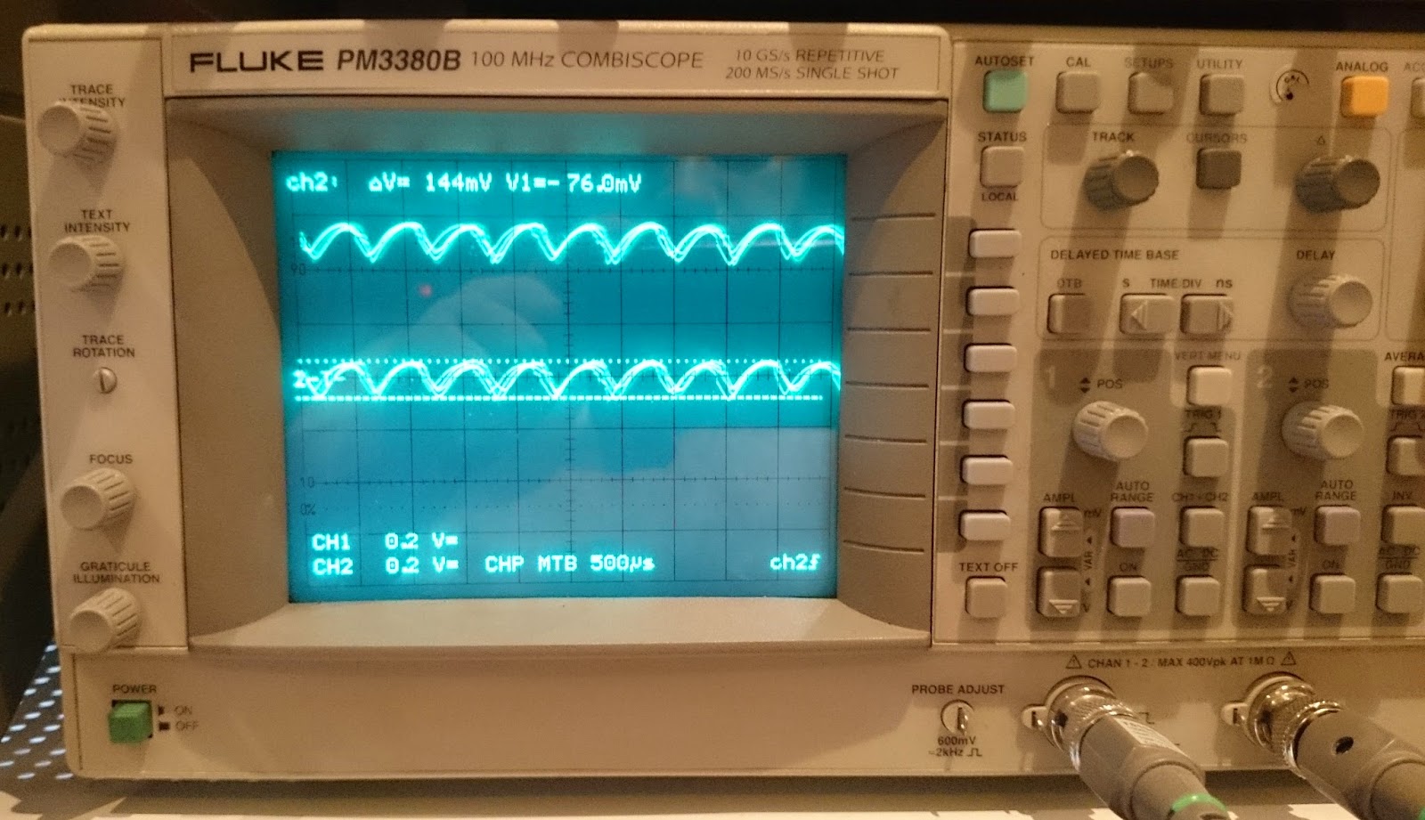
03/11/2015 at 10:32 • 0 commentsIf I put a diode in series of the motor, the diode will close briefly every time the motor brush step from one commutator segment to the next. This happening because of the sudden change in the magnetic field of the motor. When this change happens the the motor's windings are try to work against the power source, creating a negative current pulse (sorry for my phrasing, I'm not a native English speaker, and my study of physics happened long ago). This can be measured:
![]()
Ok, we can measure the frequency of the above pulse, but I thought, not to feed this signal directly into an MCU, so I did some shaping before.
First of all the signal decoupled with a 1uF capacitor, to keep just the AC part. After this I filtered out the frequencies above the the maximum I can get.
BTW what is the maximum here? The motor has 15000 rpm maximum rotational speed. This ok, but to keep some room, we can start to calculate from 30000 rpm. It should be devided by 60 to get the revolutions per second, and multiply by 12 what is the number of the segments in the commutator. This gives to us 6kHz. Everything above this can be eliminated. The filter in the current circuit has ~7.5kHz:
![]()
The filtering is needed because of the switching noise coming from the controller (In the further development this noise will be reduced as much as I can)
The filtered signal is fed into an MCP6002 opamp after transposed to the half supply voltage (2.5V in this case). The opamp is acting as a Schmitt trigger. The hysteresis is set to ~35mV. This is high enough to eliminate the remaining noise but low enough to be able to catch the signal what is around 200mV. At the output of the opamp is a stable square wave what is proportional to the rotational speed of the motor. -
Theory of operation: Controller
03/11/2015 at 10:26 • 0 commentsI needed a switching MOSFET driver for the motor. From the first look it looked simple, but finally it came out that I need DC to drive the motor, with the least possible amount of noise and clearly high side switching. The circuit come out is closer to a buck regulator then a simple MOSFET switch.
I chosen a P-Chanel MOSFET for switching, because the required maximum current (~8.5A) can be easily handled with a relatively low cost MOSFET and eliminate the rather tricky circuit or specialized driver IC needed for driving an N-Chanel MOSFET on the high side.
When the incoming PWM signal get high, the Q2 start to conduct and pull down the gate of the MOSFET 10V below the 48V rail (restricted by the D3 zener) and the FET start to conduct. The 50mA what can flow here is enough to fill the gate capacitor of the FET. At the same time Q1 transistor's base pulled down keeping the Q1 in nonconducting state (the D2 is used to protect Q1 base to not go bellow the BE diode rated voltage). When the PWM signal goes low, the Q2 stop conducting allowing the FET gate to go high, but because of the high gate capacitance the FET would not switch off fast enough. Here come the role of the Q2. When the Q1 stop conducting the Q2's base is pulled up to the rail through R1-D2. The Q2 start to conduct and the FET's gate capacitor gets discharged through Q2.
The high energy square wave generated by the MOSFET is fed to the L4-C8-D4 buck network creating a DC signal proportional to the PWM signal. -
It works
02/21/2015 at 05:18 • 0 commentsLot of work finished, and also lot ahead.
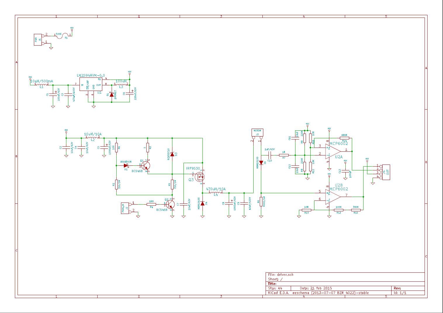
The driver and the measurement is working:
And here is the current state of the schematics:
![]()
I'll explain the operation in a later post. Now just the things still ahead:
- A few mV noise is still on the motor's rail, what I want to filter out. In addition I want to change the current passive measurement filter to a 2nd order active Chebyshev filter.
- The complete PWM generator, frequency measurement, display, PID controller is ahead.
-
Proof of concept
08/15/2014 at 13:41 • 0 commentsFirst of all I wanted to proof if anything can be measured on a DC motor what is in connection of the rpm.
I pick up some random old 12V DC fan from the drower connected to my bench PSU through a small serial resistor and connented the resistor to my oscilloscope.
As you can see on the picture, the measurable spike is there.
DC Motor Controller for CNC Router
DC motor rotational speed controller for Chinese CNC3040 spindle motor without any kind of encoder