-
Code
05/03/2015 at 21:33 • 6 commentsWell, I never posted any code for that project, because I forgot it, let's correct that:
Arduino Pro Mini 5V w/ ATmega328
/*
  OpenOpener :
  dual swing-gate automatic gate opener
*/

// pins definitions :
// D0  - USB Rx               shunt M1 - A0
// D1  - USB Tx               shunt M2 - A1
// D2  - BP stop                       - A2
// D3  - Remote Control                - A3
// D4  - Relay M1A         Rpi i2c SDA - A4
// D5  - Relay M1B         Rpi i2c SCL - A5
// D6  - Relay M2A
// D7  - Relay M2B
//
// D8  - BP close
// D9  - BP open
// D10 - PWM M1
// D11 - PWM M2
// D12 - relay FlashLight
// D13 -
#define PIN_RELAY_M1A  4  // D3 relay board
#define PIN_RELAY_M1B  5  // D2 relay board
#define PIN_RELAY_M2A  6  // D1 relay board
#define PIN_RELAY_M2B  7  // D0 relay board

#define PIN_BP_STOP  2  // pin 2 for external interrupt
#define PIN_BP_OPEN  9
#define PIN_BP_CLOSE 8

#define PIN_REMOTE 3

#define PIN_PWM_M1 10
#define PIN_PWM_M2 11

#define PIN_FLASHLIGHT 12

#define PIN_CURRENT_M1 0  // analog A0
#define PIN_CURRENT_M2 1  // analog A1

// defines
//#define _DEBUG_BP
#undef _DEBUG_BP

// parameters:
#define DELAYINMILLISEC 4000
#define TIMEOUTMOTORINMILLISEC /*5000*/30000
#define TIME_INHIBIT_IMES_INMILLISEC 1000
#define MAX_OVERCURRENT_IN_AMP  3.0f
#define MIN_MOTOR_CURRENT_IN_AMP 0.2f  // minimum value when a motor spins (failure sensor detection)
#define IMESARRAY_SIZE 10

// enum
enum OpeningStates {
  INIT_OPEN,
  OPEN_M1,
  OPEN_DELAY,
  OPEN_M2,
  WAIT_OPEN_END,
  END_OPEN
};

enum ClosingStates {
  INIT_CLOSE,
  CLOSE_M1,
  CLOSE_DELAY,
  CLOSE_M2,
  WAIT_CLOSE_END,
  END_CLOSE
};

enum RemoteStates {
  STATE_STOP1,  // 0
  STATE_OPEN,   // 1
  STATE_STOP2,  // 2
  STATE_CLOSE   // 3
};

// global variables
unsigned char StopCount;
unsigned char nextState;
boolean bOpening;  // flag for opening gates
boolean bClosing;  // flag for closing gates
unsigned long timeStartOpenM1 = 0;
unsigned long timeStartOpenM2 = 0;
unsigned long timeStartCloseM2 = 0;
unsigned long timeStartCloseM1 = 0;
boolean bStopNow = false;
float currentM1_inAmp = 0.0f;
float currentM2_inAmp = 0.0f;
unsigned char currentState = STATE_STOP1;  // remote control state machine
unsigned char newState = STATE_STOP1;  // remote control state machine;
unsigned long lastTimeCheck = 0;
unsigned long timeCurrent = 0;  // check currents values from shunt resistors
int ImesCount = 0;
int I1array[IMESARRAY_SIZE] = {0};
int I2array[IMESARRAY_SIZE] = {0};
int modeM1 = 0;
int modeM2 = 0;
bool isM1Stopped = false;
bool isM2Stopped = false;
unsigned long timeStartFlashLight = 0;
boolean FlashLightState = false;

// setup:
void setup() {
  // init globals
  StopCount = 0;
  nextState = 0;
  bOpening = false;
  bClosing = false;

  // output pins:
  pinMode(PIN_RELAY_M1A, OUTPUT); digitalWrite(PIN_RELAY_M1A, LOW);
  pinMode(PIN_RELAY_M1B, OUTPUT); digitalWrite(PIN_RELAY_M1B, LOW);
  pinMode(PIN_RELAY_M2A, OUTPUT); digitalWrite(PIN_RELAY_M2A, LOW);
  pinMode(PIN_RELAY_M2B, OUTPUT); digitalWrite(PIN_RELAY_M2B, LOW);
  pinMode(PIN_FLASHLIGHT, OUTPUT), digitalWrite(PIN_FLASHLIGHT, LOW);

  // input pins:
  pinMode(PIN_BP_OPEN, OUTPUT); digitalWrite(PIN_BP_OPEN, LOW);
  pinMode(PIN_BP_CLOSE, OUTPUT); digitalWrite(PIN_BP_CLOSE, LOW);
  pinMode(PIN_BP_STOP, OUTPUT); digitalWrite(PIN_BP_STOP, LOW);
  pinMode(PIN_REMOTE, INPUT);

  // Serial link
  Serial.begin(9600);
  Serial.println("OpenOpener");

  // interrupt pin for "remote control" input pin
  attachInterrupt(1, RemoteEvent, RISING);

  StopGates();
}

// loop:
void loop() {
  // current acquisition every 10ms:
  if( (millis()-timeCurrent)>=10 ) {
    timeCurrent = millis(); // reinit current chrono

    I1array[ImesCount] = analogRead(PIN_CURRENT_M1);

    I2array[ImesCount] = analogRead(PIN_CURRENT_M2);

    ImesCount++;
    if(ImesCount >= 10) {
      ImesCount = 0;

      // median filter
      isort(I1array, IMESARRAY_SIZE);
      modeM1 = mode(I1array, IMESARRAY_SIZE);
      currentM1_inAmp = (float)(modeM1)*5.0f/1024.0;  // 1024 <-> 5V=5A

      isort(I2array, IMESARRAY_SIZE);
      modeM2 = mode(I2array, IMESARRAY_SIZE);
      currentM2_inAmp = (float)(modeM2)*5.0f/1024.0;  // 1024 <-> 5V=5A
    }
  }

  // read buttons:
  boolean bStop = false/*digitalRead(PIN_BP_STOP)*/;
  boolean bOpen = false/*digitalRead(PIN_BP_OPEN)*/;
  boolean bClose = false/*digitalRead(PIN_BP_CLOSE)*/;

#ifdef _DEBUG_BP
  // debug:
  unsigned long static waitalittle;
  if(millis()-waitalittle > 500) {
    waitalittle = millis();
    Serial.print("bStopNow:"); Serial.print(bStopNow); Serial.print("; bOpening:"); Serial.print(bOpening); Serial.print("; bClosing:"); Serial.println(bClosing);
  }
#endif // _DEBUG_DP

  // TODO: debounce buttons

  // remote control read:
  if(newState != currentState) {  // remote control detection
    switch(newState) {
      case STATE_STOP1:
      case STATE_STOP2:
        bStop = true;
        bStopNow = true;
      break;
      case STATE_OPEN:
        bOpening = true;
        nextState = INIT_OPEN;
      break;
      case STATE_CLOSE:
        bClosing = true;
        nextState = INIT_CLOSE;
      break;
      default: bStopNow = true;
    }
    currentState = newState;
    Serial.print("current state:"); Serial.println(currentState);
    Serial.print("bOpen:"); Serial.print(bOpen); Serial.print("; bClose:");Serial.println(bClose);
    Serial.print("bStopNow:"); Serial.print(bStopNow); Serial.print("; bOpening:"); Serial.print(bOpening); Serial.print("; bClosing:"); Serial.println(bClosing); Serial.println("");
  }

  // set flag for state machines
  if(bOpen && !bStopNow && !bOpening && !bClosing) {
    bOpening = true;  // flag to start opening process
    nextState = INIT_OPEN;
    newState = STATE_OPEN;
  }
  else if(bClose && !bStopNow && !bClosing && !bOpening) {
    bClosing = true;  // flag to start closing process
    nextState = INIT_CLOSE;
    newState = STATE_CLOSE;
  }

  // state machines
  if(!bStopNow ) {  // until a stop condition appears
    if(bOpening) {
      nextState = fsmOpen(nextState);
      if(nextState == END_OPEN) {
        StopGates();  // stop
        bOpening = false;  // end of opening process state machine
        newState = STATE_STOP2;
        SendMessage("End of opening process.");
      }
    }
    else if(bClosing) {
      nextState = fsmClose(nextState);
      if(nextState == END_CLOSE) {
        StopGates();  // stop
        bClosing = false;  // end of opening process state machine
        newState = STATE_STOP1;
        SendMessage("End of closing process.");
      }
    }
  }
  else {
    StopGates();
  }

  if(bStopNow) {  // press "open" or "close" button to release the "stop" state
    StopGates();
    bStopNow = false;
    bOpening = false;
    bClosing = false;
    if(currentState == STATE_OPEN) { newState = STATE_STOP2; }
    else if (currentState == STATE_CLOSE) { newState = STATE_STOP1; }
    else { newState = currentState; }
    SendMessage("StopEvent");
    Serial.print("Stop count: "); Serial.println(StopCount); Serial.println("");
  }
}

void StopGates() {
  // stop the gates
  digitalWrite(PIN_RELAY_M1A, LOW);
  digitalWrite(PIN_RELAY_M1B, LOW);
  digitalWrite(PIN_RELAY_M2A, LOW);
  digitalWrite(PIN_RELAY_M2B, LOW);
  isM1Stopped = true;
  isM2Stopped = true;
  ResetFlashLight();
  SendMessage("stop");
}

void StopGateM1() {
  // stop the gate M1
  digitalWrite(PIN_RELAY_M1A, LOW);
  digitalWrite(PIN_RELAY_M1B, LOW);
  isM1Stopped = true;
  SendMessage("stop M1");
}

void StopGateM2() {
  // stop the gate M2
  digitalWrite(PIN_RELAY_M2A, LOW);
  digitalWrite(PIN_RELAY_M2B, LOW);
  isM2Stopped = true;
  SendMessage("stop M2");
}

void OpenGateM1() {
  // open gate motor M1
  digitalWrite(PIN_RELAY_M1A, HIGH);
  digitalWrite(PIN_RELAY_M1B, LOW);
  isM1Stopped = false;
  SendMessage("opening 1st gate...");
}

void OpenGateM2() {
  // open gate motor M2s
  digitalWrite(PIN_RELAY_M2A, HIGH);
  digitalWrite(PIN_RELAY_M2B, LOW);
  isM2Stopped = false;
  SendMessage("opening 2nd gate...");
}

void CloseGateM1() {
  // close gate motor M1
  digitalWrite(PIN_RELAY_M1A, LOW);
  digitalWrite(PIN_RELAY_M1B, HIGH);
  isM1Stopped = false;
  SendMessage("closing 1st gate...");
}

void CloseGateM2() {
  // close gate motor M2
  digitalWrite(PIN_RELAY_M2A, LOW);
  digitalWrite(PIN_RELAY_M2B, HIGH);
  isM2Stopped = false;
  SendMessage("closing 2nd gate...");
}

void SendMessage(char *Message) {
  Serial.println(Message);
}

void StopEvent() {
  StopCount++;
  bStopNow = true;  // memorize "stop" button
}

void RemoteEvent() {
  switch(currentState) {
    case STATE_STOP1: newState = STATE_OPEN;  break;  // from stop to open
    case STATE_OPEN:  newState = STATE_STOP2; break;  // from open to stop
    case STATE_STOP2: newState = STATE_CLOSE; break;  // from stop to close
    case STATE_CLOSE: newState = STATE_STOP1; break;  // from close to stop
    default: newState = STATE_STOP1;
  }
//  SendMessage("Remote Control event.\r\n");
}

unsigned char fsmOpen(unsigned char state) {
  unsigned char returnState = END_OPEN;  // default

  // check overcurrent at every iteration to stop gate in case of obstacle
  // M1 overcurrent test:
  if( (state > OPEN_M1) && ( (millis()-timeStartOpenM1) >= TIME_INHIBIT_IMES_INMILLISEC && (isM1Stopped == false) ) ) {  //1s inhibit current measure
    if(currentM1_inAmp > MAX_OVERCURRENT_IN_AMP) {
      char msg[40];
      int n = sprintf(msg, "M1 overcurrent detect: ");
      dtostrf(currentM1_inAmp, 3, 1, msg+n);
      SendMessage(msg);
      StopGateM1();  // halt M1
    }
    else if(currentM1_inAmp < MIN_MOTOR_CURRENT_IN_AMP && (isM1Stopped == false) ) {
      // no current detection : maybe a sensor failure => STOP
      SendMessage("No M1 current value!");
    }
  }
  // M2 overcurrent test:
  if( (state > OPEN_M2 ) && ( (millis()-timeStartOpenM2) >= TIME_INHIBIT_IMES_INMILLISEC && (isM2Stopped == false) ) ) {  //1s inhibit current measure
    if(currentM2_inAmp > MAX_OVERCURRENT_IN_AMP) {
      char msg[40];
      int n = sprintf(msg, "M2 overcurrent detect: ");
      dtostrf(currentM2_inAmp, 3, 1, msg+n);
      SendMessage(msg);
      StopGateM2();  // halt M2
    }
    else if(currentM2_inAmp < MIN_MOTOR_CURRENT_IN_AMP && (isM2Stopped == false) ) {
      // no current detection : maybe a sensor failure => STOP
      SendMessage("No M2 current value!");
    }
  }
  // stop if needed:
  if(state == END_OPEN) {
    StopGates();
    return END_OPEN;  // exit fsm
  }

  switch(state) {

    case INIT_OPEN:
      SendMessage("Start Opening process...");
      timeStartOpenM1 = 0;
      timeStartOpenM2 = 0;
      lastTimeCheck = millis();
	  SetFlashLight();
      returnState = OPEN_M1;  // next state
    break;

    case OPEN_M1:
      timeStartOpenM1 = millis();  // memorize date for opening M1
      OpenGateM1();  // open first gate
      returnState = OPEN_DELAY;  // next state
    break;

    case OPEN_DELAY:
      if( (millis() - timeStartOpenM1) >=  DELAYINMILLISEC ) {
        returnState = OPEN_M2;  // next state
      }
      else {
        returnState = OPEN_DELAY;  // stay in delay
      }
    break;

    case OPEN_M2:
      OpenGateM2();
      timeStartOpenM2 = millis();  // memorize date for opening M2
      returnState = WAIT_OPEN_END;
    break;

    case WAIT_OPEN_END:
      if( (millis() - timeStartOpenM1) >=  TIMEOUTMOTORINMILLISEC ) {  // time elapsed since M1 start
        returnState = END_OPEN;  // next state
      }
      else {
        if(isM1Stopped && isM2Stopped) {  // both motors are stopped, np need to wait more
          returnState = END_OPEN;  // next state
        }
        else {
          returnState = WAIT_OPEN_END;  // stay in delay
        }
      }
    break;

    case END_OPEN:
      StopGates();
      returnState = END_OPEN;
    break;

    default:
      StopGates();  // stop when default
      returnState = END_OPEN;
  }

  if( (millis()-lastTimeCheck) >= 1000 )
  {
    lastTimeCheck = millis();
    Serial.print("Opening time: "); Serial.print( (millis()-timeStartOpenM1)/1000 );  // time since the begining of the opening fsm
    Serial.print("; Current M1 = "); Serial.print(currentM1_inAmp); Serial.print("\tCurrent M2 = "); Serial.println(currentM2_inAmp);
  }

  return returnState;
}

unsigned char fsmClose(unsigned char state) {
  unsigned char returnState = END_CLOSE;

  // check overcurrent at every iteration to stop gate in case of obstacle
  // M2 overcurrent test:
  if( (state > CLOSE_M2 ) && ( (millis()-timeStartCloseM2) >= TIME_INHIBIT_IMES_INMILLISEC && (isM2Stopped == false) ) ) {  //1s inhibit current measure
    if(currentM2_inAmp > MAX_OVERCURRENT_IN_AMP) {
      char msg[40];
      int n = sprintf(msg, "M2 overcurrent detect: ");
      dtostrf(currentM2_inAmp, 3, 1, msg+n);
      SendMessage(msg);
      StopGateM2();  // halt motor
    }
    else if(currentM2_inAmp < MIN_MOTOR_CURRENT_IN_AMP && (isM2Stopped == false) ) {
      // no current detection : maybe a sensor failure => STOP
      SendMessage("No M2 current value!");
    }
  }
  // M1 overcurrent test:
  if( (state > CLOSE_M1 ) && ( (millis()-timeStartCloseM1) >= TIME_INHIBIT_IMES_INMILLISEC && (isM1Stopped == false) ) ) {  //1s inhibit current measure
    if(currentM1_inAmp > MAX_OVERCURRENT_IN_AMP) {
      char msg[40];
      int n = sprintf(msg, "M1 overcurrent detect: ");
      dtostrf(currentM1_inAmp, 3, 1, msg+n);
      SendMessage(msg);
      StopGateM1();  // halt motors
    }
    else if(currentM1_inAmp < MIN_MOTOR_CURRENT_IN_AMP && (isM1Stopped == false) ) {
      // no current detection : maybe a sensor failure => STOP
      SendMessage("No M1 current value!");
    }
  }
  // stop if needed:
  if(state == END_CLOSE) {
    StopGates();
    return END_CLOSE;  // exit fsm
  }

  switch(state) {

    case INIT_CLOSE:
      SendMessage("Start Closing process...");
      timeStartCloseM2 = 0;
      lastTimeCheck = millis();
	  SetFlashLight();
      returnState = CLOSE_M2;  // next state
    break;

    case CLOSE_M2:
      timeStartCloseM2 = millis();  // memorize date for closing M2
      CloseGateM2();  // close first gate
      returnState = CLOSE_DELAY;  // next state
    break;

    case CLOSE_DELAY:
      if( (millis() - timeStartCloseM2) >=  DELAYINMILLISEC/*-3000*/ ) {  // TODO: -3000 for debug: erase it quickly!
        returnState = CLOSE_M1;  // next state
      }
      else {
        returnState = CLOSE_DELAY;  // stay in delay
      }
    break;

    case CLOSE_M1:
      CloseGateM1();
      returnState = WAIT_CLOSE_END;
    break;

    case WAIT_CLOSE_END:
      if( (millis() - timeStartCloseM2) >=  TIMEOUTMOTORINMILLISEC ) {
        returnState = END_CLOSE;  // next state
      }
      else {
        if(isM1Stopped && isM2Stopped) {
          return END_CLOSE;
        }
        else {
          returnState = WAIT_CLOSE_END;  // stay in delay
        }
      }
    break;

    case END_CLOSE:
      StopGates();
      returnState = END_CLOSE;
    break;

    default:
      StopGates();  // stop when default
      returnState = END_CLOSE;
  }

  if( (millis()-lastTimeCheck) >= 1000 )
  {
    lastTimeCheck = millis();
    Serial.print("Closing time: "); Serial.print( (millis()-timeStartCloseM2)/1000 );  // time since the begining of the closing fsm
    Serial.print("; Current M1 = "); Serial.print(currentM1_inAmp); Serial.print("\tCurrent M2 = "); Serial.println(currentM2_inAmp);
  }

  return returnState;
}

void isort(int *a, int n)
{
  //Sorting function
  // sort function (Author: Bill Gentles, Nov. 12, 2010)
  //  *a is an array pointer function
  for (int i = 1; i < n; ++i) {
    int j = a[i]; int k;
    for (k = i - 1; (k >= 0) && (j < a[k]); k--) {
      a[k + 1] = a[k];
    }
    a[k + 1] = j;
  }
}

int mode(int *x,int n){
  //Mode function, returning the mode or median.
  int i = 0;
  int count = 0;
  int maxCount = 0;
  int mode = 0;
  int bimodal;
  int prevCount = 0;

  while(prevCount&count>maxCount){
      mode=x[i];
      maxCount=count;
      bimodal=0;
    }
    if(count==0){
      i++;
    }
    if(count==maxCount){//If the dataset has 2 or more modes.
      bimodal=1;
    }
    if(mode==0||bimodal==1){//Return the median if there is no mode.
      mode=x[(n/2)];
    }
    return mode;
  }

void SetFlashLight() {
  timeStartFlashLight = millis();  // start flash light
  FlashLightState = true;
  digitalWrite(PIN_FLASHLIGHT, HIGH);
  SendMessage("Flashlight ON");
}

void ResetFlashLight() {
  FlashLightState = false;
  digitalWrite(PIN_FLASHLIGHT, LOW);
  SendMessage("Flashlight OFF");
}
(It's not very easy to read because of the state machines.)
-
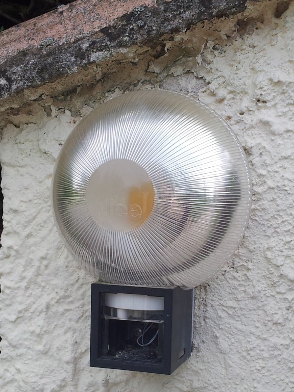
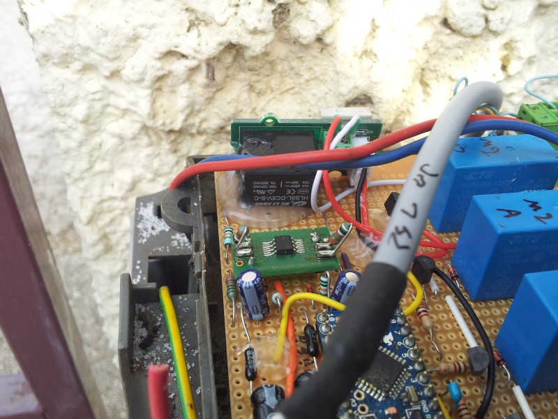
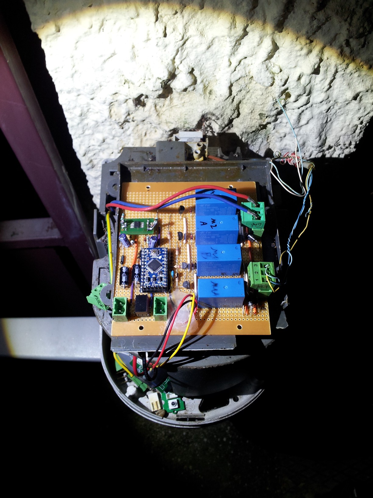
Adding flashing light
05/03/2015 at 21:23 • 0 commentsA little update to support the existing flashing light to my custom dual motor controller.
![]()
It's a simple 24V bulb with a 555 integrated timer and a TIP120 transistor on a PCB (I should have done a photo of the existing PCB...)
It's very simple to use: just apply 24V (DC or AC, a Graetz diode bridge rectifies if AC and allow plug any polarity you want) and the light bulb blinks every 5 seconds or so.
To apply 24V to the light, I used a Grove relay module from seeedstudio connected to pin D12 of the Arduino board.
![]()
It's ugly but it works.
-
TODO list
01/22/2015 at 00:51 • 0 commentsMy proto board does its minimal requirement: I can open an close the automatic gate with a remote control.
Yet, I have some bugs to fix:
- add a proper antenna to the 433MHz receiver: in open field, I can open and close the automatic gate about 10-15 meters away from the receiver. But when I'm in my car, with an athermal coated windshield which filters IR to prevent overheating in summer but blocks also some useful RF data links, it only works 2-3 meters away. It would be a great improvement to add an external antenna with some coaxial cable to the receiver. For the moment I only have a piece of copper wire badly positioned in the case. I would have a better sensivity if an antenna was on a door post.
- I use an external interrupt pin on the arduino board (INT0 - digital pin D2) connected to the 5V logic output pin of the remote control receiver. This thing is a little picky and should be more debounced. As the remote control has only one push button, a state machine follows a sequence like this: STOP - OPEN - STOP - CLOSE - STOP - OPEN ... at every pulse generated from the remote control. Sometimes, when from a stop state, it skips an OPEN or CLOSE state immediately to a STOP state if a glitch happens. Maybe some more coding could fix it (or a more filtered/flip-flopped D2 pin).
- current sensing: as the motor power supply is only rectified, but not filtered nor regulated, the current in the motors is pulsed at 100Hz (2x50 Hz mains frequency in Europe). I am currently using a peak detector (10xopamp + diode + cap//resistor) and a basic RC low-pass filter to smooth it out, but it needs to be tuned.
- current sensing without diff amplifier: when the 2 motors run, the shunt resistor "see" the other mother and the current value is impacted. By tweaking threshold values in software, it works, but it is not satisfying. I need to work to isolate the both current measurements from the 2 motors.
Things that I would like to improve:
- clean the power supply to power motors and logic board from the same 24V rectified. I am using a 24V regulated power brick temporally in order to prevent microcontroller brown-outs. Kinda ugly, I would prefer just one cable from mains power.
- add a mosfet to switch the original flashing light. It is annoying not having a visual indicator when the opener is doing something.
- add an xbee wireless uart to do some checks from my house (especially when it's raining outside). I have a little command interpreter in the arduino code which is a more user friendly than a single push button remote control.
- add rfid (because I can).
- replace the proto board with a clean custom pcb to save some real estate in the case.
- software: estimate the angular position of a gate by timing it from a mechanical limit. For fun, maybe, but it can be useful when it stops before gates reaches their fully open or fully close position as you need to maintain about 3 seconds between each gate to prevent them from colliding.
Things to give up:
- connecting a raspberry pi is not very useful at the moment. Maybe if I add a camera module, but I don't feel like doing it until next spring.
- watchdog timer: I need to double check AVR datasheets but it seems that 8 seconds is a max. It also seems that the bootloader has issue with it. So, I am relying on the timeouts I implemented in software to return from error states.
-
First goal achieved
01/21/2015 at 23:52 • 0 comments![]()
It's been 2 months since I have installed my proto board and it works barely well.
It is a minimal system compared to my first intentions: it justs open an close the 2 arms of my opener from the original remote control (433MHz).
I made some adjustements to make it usable before winter:
- no more mosfet pwm control to slow down the motors before they stall. At the nominal voltage, everything runs fine as it take about 20 seconds to fully open, or close, the doors. I don't want to slow it down because, even when an arm reaches its mechanical limit, it is slow enough not to damage anything. So, let's use the maximal speed.
- to make my proto board fits in the original case, I switched to an arduino pro mini
- as the original 24V is just a rectified 24V without filtering (I removed the, maybe dying, original big electrolytic cap) it only powers motors. Yet, I added a 24V regulated power supply from the main ac power supply (230V here in Europe) stepped down to 5V to power the logic part of the system (little Traco Power integrated switching module under the arduino Pro Mini).
-
Always check power supply first
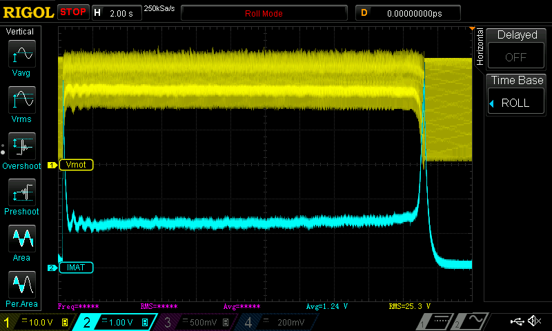
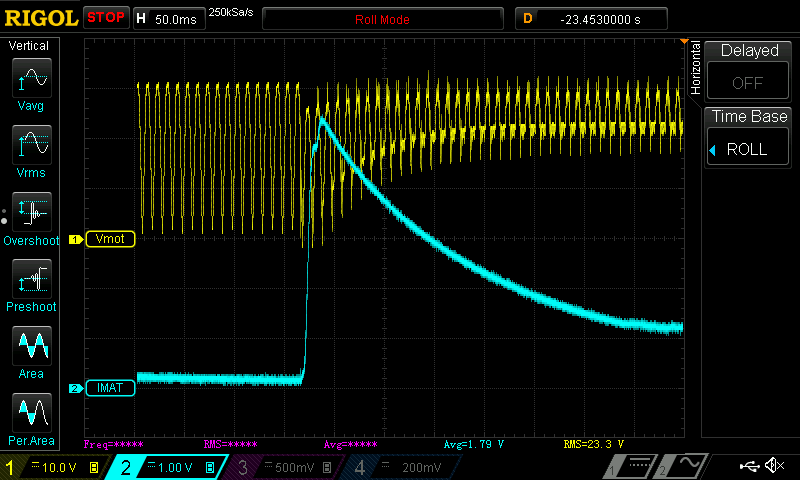
09/29/2014 at 19:42 • 0 commentsOk, I assumed that my 24V power supply was somewhat regulated and it's not. Just a Graetz diode bridge behind a transformer inside the motor case of my existing opener. As a result the voltage that is powering the motors is just redressed but not regulated. As you can imagine, when a (dc) motor is driven, the current that flows through it follows the voltage waveform. Unfortunately, my opener controller was supposed to stop an arm when an overcurrent is detected. Because of the non-continuous nature of the current, I coudn't sample shunt resistor voltage at random time to detect an overcurrent stall condition. I finally decided to solve it in hardware with a cheap diode/cap peak detector followed by a lowpass filter. I also added a median filter in software to avoid artefact from the shunt resistor. I will add oscilloscope captures to illustrate it, but I have a nice stable current value. It is not as accurate as a rms-to-dc converter but I don't need the exact current value: I'm only interested in the trend to dectect that a motor is stalling. So far, so good, I will continue to make my own opener controller in my spare time.
Yellow trace : "24V" power supply (rectified, not filtered nor regulated)
Blue trace : motor current (1V = 1A : 0.1ohm shunt resistor and a x10 amplifier)
![]()
On average, a motor sinks 1.3A and a peak of 5+Amps occurs when the motor starts and when it stalls.
A close up:
![]()
-
HF pinout guessing
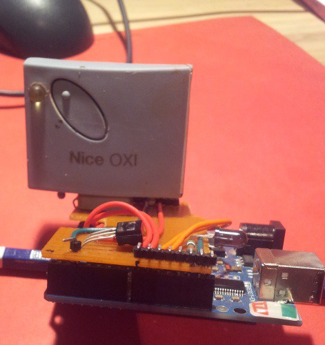
08/25/2014 at 22:45 • 1 commentI own an OXI receiver with a few remote controls. As I don't have a pinout of the receiver, I checked which of the 4 output pins react when the remote control is pushed.
![]()
I connected the 4 output of the 433MHz HF receiver to 4 digital inputs of an Arduino Duemillanove (with a piece of breadboard I already have for IR testing).
With a simple sketch, I detected an output pin toggles for about 500ms when one of the remote control's buttons is pushed. This receiver output will be connected to a digital input of my dual gate controller board.
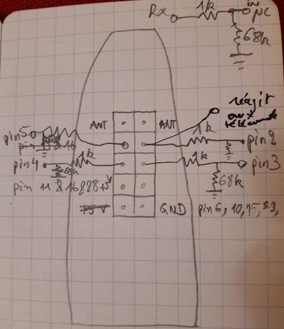
The forth pin of the 10-pin header is toggling:
thin edge of the oxi Rx
xx
xx <- this pin is toggling
xx
xx
xx
(thick edge)
![]()
pin 1 & 2: antenna
pin 4: signal
pin 7: +5V
pin 10: GND
-
Breadboarding time (sort of)
08/25/2014 at 22:32 • 0 comments![]()
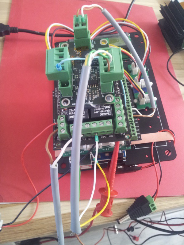
As a proof of concept, I stacked a few Arduino shields to test if I can stop a gate with overcurrent detection. My setup is composed of:
- (mandatory these days) Arduino Uno
- seeedstudio grove shield, (very handy) to add 3 push buttons: Open, close and stop test functions
- protoscrewshield with screw terminals to connect power supplies, motors, ...
- relay shield: 4x 3Amps 24V relays
- a revamped board of mine (hot-glued on top) with (very basic non-inverting) amplifiers and 0.100ohms shunt resistors.
On my installation a motor sinks about 0.5A in normal conditions. I measured a 5A stall condition, so I setted a 2.5A limit to stop a motor. An inhibition time of 1 second is used to ignore the first second when a motor starts and its currents consumption increases before stabilize after about one second.
I used a dummy load from arachnid labs to test if the microcontroller triggers when current reaches its limit.
As the current shunt voltage analogRead() function only get a sample from the AtMega controller, I will add some sort of filtering to dampen the spike that might occur and the voltage shunt measurement. (Probably a moving average filter).
-
You shall not pass
08/19/2014 at 00:07 • 0 comments...unless you have the remote control, the rfid tag, or whatever makes the input detect a pulse.
I want to keep the remote control as simple as possible: just one button. So I have to implement a finite 4-states machine: OPEN - STOP - CLOSE - STOP. One clic on the open opens the gates, an other stop them, an other make them close and another one stop them.
The motion controller detects automatically (when a sufficient time has passed) that both gate are in the stop state with the current sense system. In this case, a clic on the button starts the gate in the opposite way than the previous move (it closes if the gates are fully opened and opens it the gates are fully closed).
So any pulse on the input make the controller change between these states. In intend to remote it with 3 sources:
- the HF remote controls that I already have. As long as the receiver will work, I will use them, but they are not my best choice: they are powered by 12V batteries, that are pretty uncommun compared to 1.5V AAA-size battery.
- the rfid reader: rfid tags are cheap and can be found in many shapes (card, button, wristbands, even rings!). No power is necessary (on the tag side obviously, if there is no power on the reader side, well, ... the motors cannot move too, so it not a real problem).
- rapberry pi connected to my wifi router: it is an excuse to learn to write a small app on a smartphone and setup a decently securised web server on a pi).
That beeing said, anything that is a dry contact (push button, relay, ...) can control the gates.
-
Current sensing
08/18/2014 at 23:59 • 0 commentsTo make the motion controller automatic, it has to detect the mechanical limits of each arm of the gates. In my configuration, an arm is fully opened when the gate is in contact with the box containing a motor. The same arm is fully closed when the gate is in contact with a small piece of metal cast in concrete.
The sensing process uses a current shunt: it is a small value resitor (a few tens of ohm) that has its voltage proportional to the current that flows through it. A DC motor has approximately its torque proportional to the current that flows through it. By detecting that the current overshoots, we can determine that the torque increases and, if it increases enough, should stop.
One nice thing with H-brige is that you can reverse current in a motor to make it turn the opposit way, but another nice thing is that current direction outside the bridge is the same whatever the motor direction is. So we have the same current sign value in a motor direction or the other. This keeps us to sense the current in both ways, which is always painful. No need to have bipolar amplifier and bipolar power supplies. Great, I want to keep it simple.
-
Speed-up then slow-down
08/18/2014 at 23:48 • 0 commentsTo make a DC motor move, it has to be connected to a DC power supply. Its speed is somewhat proportional to the voltage value. The more the voltage value is (until its nominal voltage), the more the value of the speed of the motor is (until its nominal velocity). As a DC motor is pretty much a low-pass filter (as many of physics systems, by the way), you can switch its DC power supply fast enough to use it as an integrator of the voltage. To do this, you can setup a MOSFET between the motor and it DC power supply. By using a PWM output of a microcontroller (my Arduino board, in this case) connected to the gate of the transisitor, you can make as if the motor sees the mean value of the DC voltage depending of the duty cycle of the PWM output (from 0 to 100%, i.e. from 0V to it nominal voltage).
If you do this on the dc-voltage of the H-bridge, you can control the speed and the direction of the motor.
To speed the motor up, you increase the PWM duty cycle / To slow it down, you have to decrease the duty cycle.
To prevent vibration in the gate, we can use a linear acceleration, or better a S-curve (no discontinuity in the velocity) to make the motor start smoothly.
OpenOpener
Open source (software and hardware) DC motor controller for electric gates