#Installation steps
Firmware is based on Mongoose OS platform https://mongoose-os.com/ once you have installed Mongoose OS the HiGrow firmware project is available from the Library
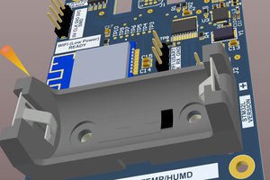
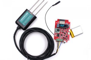
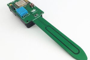
soil moisture, humidity and temperature for monitoring your plants
To make the experience fit your profile, pick a username and tell us what interests you.
We found and based on your interests.
#Installation steps
Firmware is based on Mongoose OS platform https://mongoose-os.com/ once you have installed Mongoose OS the HiGrow firmware project is available from the Library
init.jsjavascript - 3.33 kB - 02/12/2018 at 21:08 |
|
|
README.mdmarkdown - 738.00 bytes - 02/12/2018 at 21:08 |
|
|
mos.ymlyml - 1.48 kB - 02/12/2018 at 21:08 |
|
We moved the project to Mongoose OS which has a more stable and flexible library for Bluetooth.
From Mongoose is really easy to flash your board:
app are almost ready, keep you posted
Create an account to leave a comment. Already have an account? Log In.
Hi, guys!
I've started my own similar project with such board, using ESP-IDF 3.2.2 and Neil Kolban's cpp snippets on ESP32 side and Symfony + Angular 7 on server side.
And I found out that this board consume a lot of current even in deep sleep mode (about 15mA) . Does anyone have "normal" scheme for this board? My one doesn't have all circuits on it.
Hi, this project is clearly not finished, it has a bunch of consumption issues to fix yet, even in deep sleep mode the board consumption is absolutely enormous, probably 200 to 1000 times what should be guessed if the deep sleep mode hadn't been sabotaged by the idle consumption of the board. But it is nevertheless a very handy hardware to monitor plants watering. But do not even dream of using your higrow on a 18650 battery, it only works with a wire. It is extremely disapointing to see that after years the minor upgrades that are needed to turn higrow to a fantastic hardware second to none hasn't been done yet.
Some suggestions for users :
- if you want to monitor a bunch of pots you can hook up to 15 additional sensors via 3 wires cables. That is essentially the capacity of a pretty decent grow tent, so you will only need one HiGrow in each tent. By doing that you will be able to get all the 16 measurements on only one webpage/API call. BTW, you will find such additional soil sensors for less than 1.5$ each (search eBay for "Capacitive Soil Moisture Sensor v1.2"), so the whole setup won't be expensive at all. You can also get and process those info automatically in an Open Office spreadsheet by using the "Sheet > Link to External data..." function, extremely handy.
- @Adrian Blake : you read the data by connecting a web browser to the higrow on the ip address assigned by your router/internet box dhcp server. You can also set a fixed ip address when initializing the higrow wifi connection by using the following syntax instructions :
IPAddress local_IP(192, 168, 1, <your HiGrowfixedIP>);
IPAddress gateway(192, 168, 1, <yourinternetgatewayIP>);
IPAddress subnet(255, 255, 255, 0);
IPAddress primaryDNS(192, 168, 1, <yourinternetgatewayIP>);
It is then very easy to configure your internet box in order to monitor your growing plants from any browser/phone.
- @rgarciadelarosa : IMO this projet is not a scam, it will run pretty well on a usb power adapter. But I never could manage to have it running on a 18650 battery, it just doesn't work (at least in my case).
- @yann R : just use the provided sample code, it worked fine for me : "const int soilpin = 32;" Here is where I got the code : http://randomnerdtutorials.com/esp32-dht11-dht22-temperature-humidity-web-server-arduino-ide/
BTW, I saw some critics about an allegedly abusive reuse by HiGrow of previous projects. One have to consider that open source software/hardware licences used in the makers world, which are permissive (usually MIT for software / CERN OHL for hardware), allow everyone to reuse them without much constraints.
How can I read the data, temp, humidity and moisture ?
as marknitro wrote the power consumption even in deep sleep is really disapointing. I measured approx 40mA. Unfortunately there is no adequate documentation available. Nevertheless I made some modifications on the PCB wiring and I'm now at a level of 15mA in deep sleep.
One problem with the layout is, that the DHT11 and the moisture sensor curcuit is directly wired to Vcc, so the draw permanently current.
Therfore i cut off the Vcc of the DHT11 and wired it to pin 23 on the ESP. Now I can swich it on and during deep sleep it's off. This saved approx. 5 mAmps.
Next I cut off the Vcc of the moisture sensor. Exactly I cut through the Vcc line for the TLC555 circuit at the backside of the PCB. Next I soldered a wire from pin 8 of the TLC555 to pin 2 of the ESP. Now I can switch it on as well. This saved approx 20mA. I also cut off the red power LED but it seems didn't make a remarkable change.
I didn't test it right now but I assume the battery should last now for approx a week.
My next modification will be to add a LiPo fuel gauge, just have to wait for the parts to arrive from China
any news on this project I see diymore and pixelelectric sell it now
Good afternoon everyone.
After following this thread and analyzing different information.
I understand that it is a commercial project not finished.
he did not use the scheme nor the open code to be able to evolve and understand it.
the manufacturer made erroneous cards that he is selling.
It sounds like a scam.
Has someone started it?
Does anyone have the electrical blueprint?
Does someone know where to connect to send data?
etc. etc. etc.
I have two that I will try to use for other things.
do not waste your money
Hi, it seems that the rev1 board was developed by Lily GO (as seen in the list of esp32 hardware at http://esp32.net/#Hardware ).
They made a meshup of stolen hardware projects as far as I understood.
The main board is a clone of Travis Lin's Pocket 32 with on top a DHT11 temperature and humidity sensor and in the bottom part a capacitive soil humidity sensor cloned from DFRobots (https://www.dfrobot.com/wiki/index.php/Capacitive_Soil_Moisture_Sensor_SKU:SEN0193)
The main problem on the original Pocket 32 was the bad choice of ICs to manage the battery power as a commenter in the project wrote:
" If you want to use this board for long-term battery powered applications using the deep-sleep function of the ESP32, you will likely be disappointed. My measurements indicate 15mA from the battery during deep-sleep. (Note this is with rev1 silicon and Arduino IDE fixes for deep-sleep.) The ESP32 alone should only draw around 10 micro-amps during deep-sleep, not milli-amps. The seller believes the main reason is the charging system. The board uses a TP5410 which is a boost regulator which works something like this: 3.7V from 18650 battery --> TP5410 boost to 5V ---> regulated down to 3.3V for devices on the board. Further research on the internet tells me designs using this TP5410 are not meant for lengthy stand-alone battery use. Much too power inefficient. The board will be fine if constantly connected to USB for power and then 18650 will be the auto backup supply. Also, as I stated before, it doesn’t help that there is no way to programmatically monitor the actual battery voltage on this board"
I discovered this after buying 2 of this boards and a bunch of standalone capacitive soil sensors in order to monitor my plants. I'm going to use usb to power the boards ignoring the battery. Currently I'm using Arduino IDE and Cayenne MQTT Api to store the readings from the onboard sensors and I want to wxpand the system with output for automatic watering, fan, lights, etc...
If someone is interested I can post the code. Maybe it's nota complete waste of money.
It looks like lilygo t-higrow changed its hw and it now states:
Comparison before and after the soil test module G301 upgrade: (Upgrade time: September 7, 2019)
1. Changed from the original ESP32 module to a separate ESP32 chip.
2. The lithium battery was changed from the original 18650 to a 500MA lithium battery.
...
Working current: 150MA
Sleep current: 220UA
Did anybody test it? How long does it last on battery only?
Do you also know if I can control it via Alexa routines?
very interested project, I very curious about how to port the EspTouch Smart Config to Xamarin. Are you using the nuget version 1.04? Thanks
Hi i bought this board, but i cant program it using Arduino, i get the message:
A fatal error occurred: Failed to connect to ESP32: Invalid head of packet ('.')
Hi Luca,
thank you for this really cool idea. I got 2 samples of the V1 board from the sources you have mentioned. Unfortunately, one of these is already dead, probably because it ran at very low battery. The problem is described here: https://github.com/espressif/esptool/issues/263
It looks like I cannot re-vitalize this dead HiGrow board. But this shows two things:
- version 1 is not usable for long term usage, might be ok just for experimenting
- a battery measurement possibility is essential, otherwise it will not be possible, to avoid the problem described above
- maybe there is a way to switch the board off completely, when battery drops to a too low voltage. I am not so good at hardware design, thus this is something I cannot answer
- question: is it possible to add a solar panel to load the battery? Any recommendations, how/where to connect the panel?
Otherwise I added MQTT comunication to your mongoose-os based implementation and enabled deep sleep (to save battery capacity). I am happy to provide sources for these changes, if wanted.
A picture of the hardware design would be very helpful to understand what is available and how to add more features. I still do not understand the usage of the button labeled "EN" and did not try to find out, which GPIO it is connected to. The same with the LEDs -- several are on the board, but it is hard to find out, where/how they are connected.
Hello Luca, thank you for your work.
That she is the number pin of the sensor ?
to integrate soil moisture into blynk
Thank you
Este proyecto sigue vivo ??
alguien lo tiene en marcha
tengo dos tarjetas compradas para poder instalar.
muchas gracias.
Hallo Luca,
your github https://github.com/lucafabbri/HiGrow-Arduino-Esp/blob/master/HiGrowEsp32/HiGrowEsp32.ino sketch has a light sensor (pin 33).
This seems to produce random numbers around 90-110 in my case. Where is the light sensor on the board? Is it the multi pin rectangle in the center? I already played with the adc attenuation and resolution but had no luck.
I use the rev1 board with the HiGrow icon.
A circuit diagram would be very helpful. Rev 1 and Rev 2, if possible.
Btw.: I'm also missing the transistor opposite to the "H" of the Icon. What is it for?
Thank you for all your work!
Hi
I have mangoose installed on my esp32.
After that, I uploaded your program.
If I access the esp only see this page.
https://www.dropbox.com/s/dg5xm31g47d0xq0/Higrove.png?dl=0
What did I do wrong?
Hi to all,
very nice project this sensor. I would love to test it but I can't get my hardware running because of the header files. Is it possible, that you can also upload the *.h files? I'm not sure where to get them.
Thanks for your help,
Markus
Hi everyone, thanks for your support! If anyone has experience with Mongoose OS you can review the code: any improve would be really appreciated!
Hello Luca, is there any Android App available, yet?
Hi people, I have a problem with your sketch!
Error during compilation. Can tell me what to do?
I took it from here: https://github.com/lucafabbri/higrowopen
Maybe it's in the DHT sensor library.
which library do you use?
The error is this:
C:\Users\HP_DV7\Documents\Arduino\sketch\HiGrowEsp32\HiGrowEsp32.ino: In function 'void setup()':
HiGrowEsp32:50: error: 'esp_deep_sleep_enable_timer_wakeup' was not declared in this scope
esp_deep_sleep_enable_timer_wakeup(1800 * uS_TO_S_FACTOR);
^
HiGrowEsp32:51: error: 'esp_deep_sleep_pd_config' was not declared in this scope
esp_deep_sleep_pd_config(ESP_PD_DOMAIN_RTC_PERIPH, ESP_PD_OPTION_OFF);
^
C:\Users\HP_DV7\Documents\Arduino\sketch\HiGrowEsp32\HiGrowEsp32.ino: In function 'void loop()':
HiGrowEsp32:75: error: 'esp_deep_sleep_enable_timer_wakeup' was not declared in this scope
esp_deep_sleep_enable_timer_wakeup(DEEPSLEEP_SECONDS * uS_TO_S_FACTOR);
^
C:\Users\HP_DV7\Documents\Arduino\sketch\HiGrowEsp32\HiGrowEsp32.ino: In function 'void sensorsData(char*)':
HiGrowEsp32:98: error: 'class DHT' has no member named 'computeHeatIndex'
float hic = dht.computeHeatIndex(temperature, humidity, false);
^
We use the library WiFi ver 1.0 from the folder: C:\Users\HP_DV7\Documents\Arduino\hardware\espressif\esp32\libraries\WiFi We use the library HTTPClient ver 1.1from the folder: C:\Users\HP_DV7\Documents\Arduino\hardware\espressif\esp32\libraries\HTTPClient We use the library DHT from the folder: C:\Users\HP_DV7\Documents\Arduino\hardware\espressif\esp32\libraries\DHT (legacy)
We use the library WiFiClientSecure ver 1.0 from the folder: C:\Users\HP_DV7\Documents\Arduino\hardware\espressif\esp32\libraries\WiFiClientSecure exit status 1
'esp_deep_sleep_enable_timer_wakeup' was not declared in this scope
We use the library C:\Users\HP_DV7\Documents\Arduino\hardware\espressif\esp32\libraries\BLE: C:\Users\HP_DV7\Documents\Arduino\hardware\espressif\esp32\libraries\BLE
There may be a problem in the DHT library?Be so kind as to tell me!
If you need a mail: Svirik82@gmail.com
Hello, thank you for the suggestions.
Have it flashed but I'm not on the web server showing the data.
Nothing happens after flashing.
This shows the serial monitor:
ets Jun 8 2016 00:22:57
rst: 0x1 (POWERON_RESET), boot: 0x13 (SPI_FAST_FLASH_BOOT)
flash read err, 1000
ets_main.c 371
ets Jun 8 2016 00:22:57
rst: 0x10 (RTCWDT_RTC_RESET), boot: 0x13 (SPI_FAST_FLASH_BOOT)
configsip: 0, SPIWP: 0xee
clk_drv: 0x00, q_drv: 0x00, d_drv: 0x00, cs0_drv: 0x00, hd_drv: 0x00, wp_drv: 0x00
mode: DIO, clock div: 1
load: 0x3fff0018, len: 4
load: 0x3fff001c, len: 956
load: 0x40078000, len: 0
load: 0x40078000, len: 13256
entry 0x40078a90
DeviceId: 207537695927856
-1
we moved the development to Mongoose OS, you find the code here https://forum.mongoose-os.com/discussion/2011/new-contribution-higrow-plant-monitoring-sensor
Hi, im looking into this project and bought two sets of PCB from aliexpress (this is where I stumbled onto it). Before loading any code to it I discover that my two boards does not have the transistor/FET, the 3 pin SMD component in the bottom part (toward soiltail). Does it exist any electrical drawing to this board so that I can investigate the board and its components?
BR
Ice2Cool
Hi! could you share a pic? the producer made an initial version which was faulty!
Did you manage to find what component were missing?
is there a voltage divider to monitor the battery?
on which pin is it?
are there any more infos about the board?
which sensor is on which pin?
why is the github sketch not maintained?
Not on thi sversion, rev2 is based on Adafruit schematics using LiPO and voltage divider on pin 13
Hi Luca, I'd be very interested in purchasing one of your ESP32 dev boards for my project, are they available on any other online stores other than Amazon.it?
I posted the cheaper link to Aliexpress (they are almost everywhere just type higrow in your favourite repo)
Become a member to follow this project and never miss any updates
By using our website and services, you expressly agree to the placement of our performance, functionality, and advertising cookies. Learn More

 Olivier Godfroid
 Makerfabs
 Guy Cole
 yancan
Board sucks for 18650. I will sign that. In deep sleep mode it was drawing 25mA from the battery and an faint audible beep was present. I'm assuming this is all caused by some voltage regulator.
The thing works but as pat said, I'd advise against it IF you wish to run it off a battery. If cable is your thing, no problem.