Close
0%
0%

MakerFoundry

DIY Semiconductor fabrication using maskless lithography

Similar projects worth following
The goal of this project is to fab some working IC's in a relatively cheap, DIY-friendly manner.

Thanks to the work of folks like Jeri and Sam (see links), a road has been paved for amateurs to produce some simple, working transistors in their own home fab. I'm tackling this project largely as a learning experience; I don't really expect to one day fab an Intel 8080.

The project offers a lot of interesting things to learn: optics, microcontrollers, cartesian printer/plotter design, semiconductor fabrication, etc.

At best, I successfully fab a working transistor or simple circuit. At worst, I'll have built a high-resolution lithography machine which I can use to play with microfluidics or other large-feature projects.


The plan is roughly:

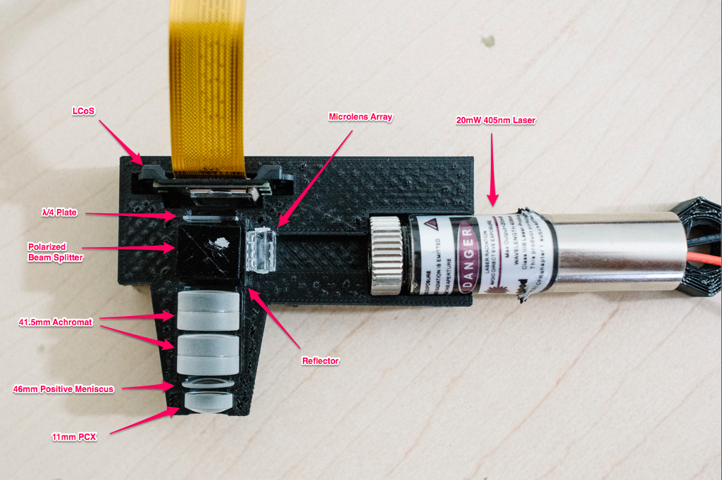
  1. Modify an LCoS pico projector to perform maskless photolithography using a 405nm laser
  2. Build a high-precision cartesian plotter for automated positioning and die exposure
  3. Work my way through IC fab and metallization
  4. Figure out wire bonding (either via an eBay machine or DIY)

Realistic goal is around 10µm. Theoretical limit of the system is ~600nm due to the 405nm laser wavelength, so I figure an order of magnitude higher is reasonable. It's also the process size of the Intel 4004 in 1971 which seems like a good goal :)

Why Maskless Lithography?

Mask generation is one of the most expensive parts of actual IC fabrication. High-quality photomasks are typically chrome-on-quartz, although cheaper/lower resolution photomasks can be created with regular soda-lime glass and photographic emulsion (e.g. a film negative... but on glass). You could probably even get away with actual film negatives, or laser-printed designs on acrylic.

Considering the target process size (1-10µm) was accomplished in the 1970's, emulsion-based photomasks is probably more historically accurate. :)

That said, there are a lot of challenges to sort out with a mask system (optics, mask production, etc). Many of these also apply to a maskless system using some kind of projector technology... so why not start there?

In addition, a maskless process opens some potentially interesting doors to play with, such as "easy" computational lithography, scanning lithography without having to move the mask, etc.

Why LCoS Pico Projector?

There are four main projection technologies at the moment: digital micromirror devices (DMD, aka DLP), liquid-crystal-on-silicon (LCoS), LCD, and laser. Laser projectors are rather expensive, so we can rule those out right away. Of the rest, LCoS tend to be available cheaply in small "pico projector" packages. There may be other advantages or disadvantages, but price was my main reason.

Why 405nm?

I've read that most photoresists are somewhat sensitive to light at 405nm, which corresponds to the "h-line" on mercury lamps. 405nm is violet light, and just on the edge of visible. Below 400 and you start to reach into UV, which is problematic to work with for many reasons. It requires better optical glass to deal with UV, any plastic in the light path will degrade, LCDs don't enjoy UV light, etc.

So the h-line seemed like a reasonable place to park my wavelength. Finally, you can buy 405nm lasers which will be more convenient to work with than a giant, hot mercury lamp.

IF, however, it turns out that photoresist does not respond to 405nm well, I may investigate "daylight resins" used in some SLA 3D printers. These resins cure with ~500nm (blue) light, and as long as I can find a solvent to dissolve them, may work as a replacement for proper photoresist.

How are you going to build the translation stage?

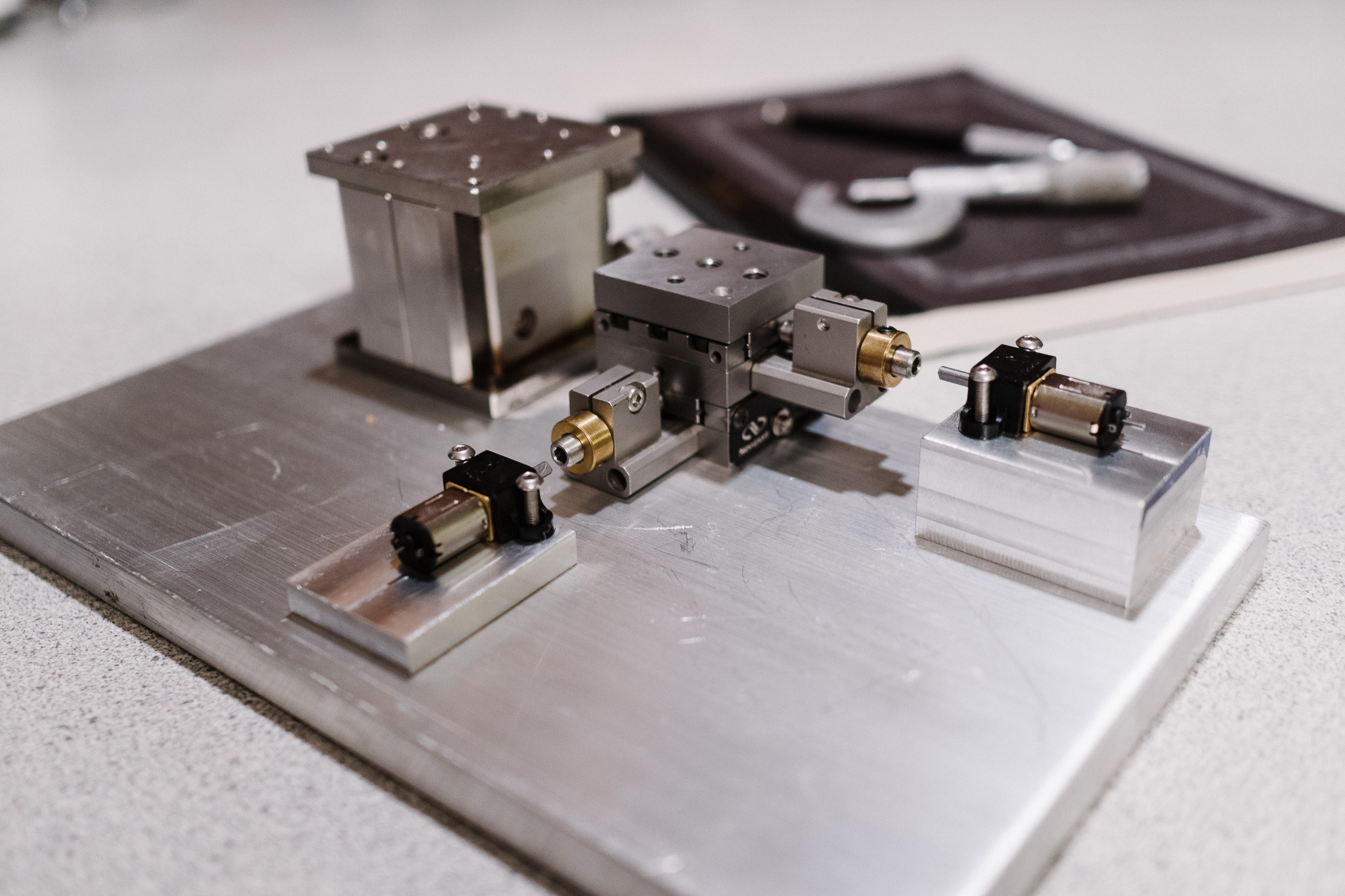
The plan is to use two aluminum CNC z-axis as the basis for the translation stage. These parts are extremely rigid, and geared with a leadscrew that provides 1mm movement per turn. Combined with some high-resolution encoded gear motors (8400 pulses per rotation), I'm hoping to eke out acceptably accurate positioning from the stage

  • A look at the XYZ setup

    polyfractal01/10/2018 at 15:09 1 comment

    Back to work!  After a long hiatus, I'm making progress on this project again.  The next step is to start building the mounting hardware for the X/Y stage, motors, vertical adjustment and optical engine itself.  

    Read more »

  • TI Releases affordable, hacker-friendly DMD board

    polyfractal08/03/2017 at 21:31 0 comments

    Welp, this would have been useful a few months ago:

    The new 0.2-inch DLP2000 chipset and $99 DLP® LightCrafter™ Display 2000 evaluation module (EVM) now make it more affordable to leverage DLP technology and design on-demand, free-form display applications such as mobile smart TVs; pico projectors; digital signage; projection displays for smart homes, smartphones and tablets; and control panels and Internet of Things (IoT) display solutions.


    Yep, TI has released a DMD (digital mirror device) chip + light engine + controller board for $99.  It's compatible with BeagleBone out of the box, but also accepts I2C and 8/16/24-bit parallel RGB video.  Which means it is the cheapest hacker-friendly DMD that exists (as the alternatives are buying an old DLP projector and tearing it apart).

    The chip by itself costs only $20, which is super cool for developing your own pico projects.

    The resolution isn't great (640 × 360), but it would certainly be ok for a hackish project like mine.  And DMD's have huge advantages over LCoS in terms of simplicity... no worrying about polarizers, etc.  UV light plays much nicer with aluminum mirrors.

    More info here:

    Pretty cool!  I'll keep this in my bag of tricks for future projects.

    Alas, my course is set for the moment.  I've committed to direct-laser writing for now, and have essentially all the components I need.  Just need to start fabricating again.  Updates to follow as I find time!

  • Furnace PID Upgrade

    polyfractal07/30/2017 at 22:17 0 comments

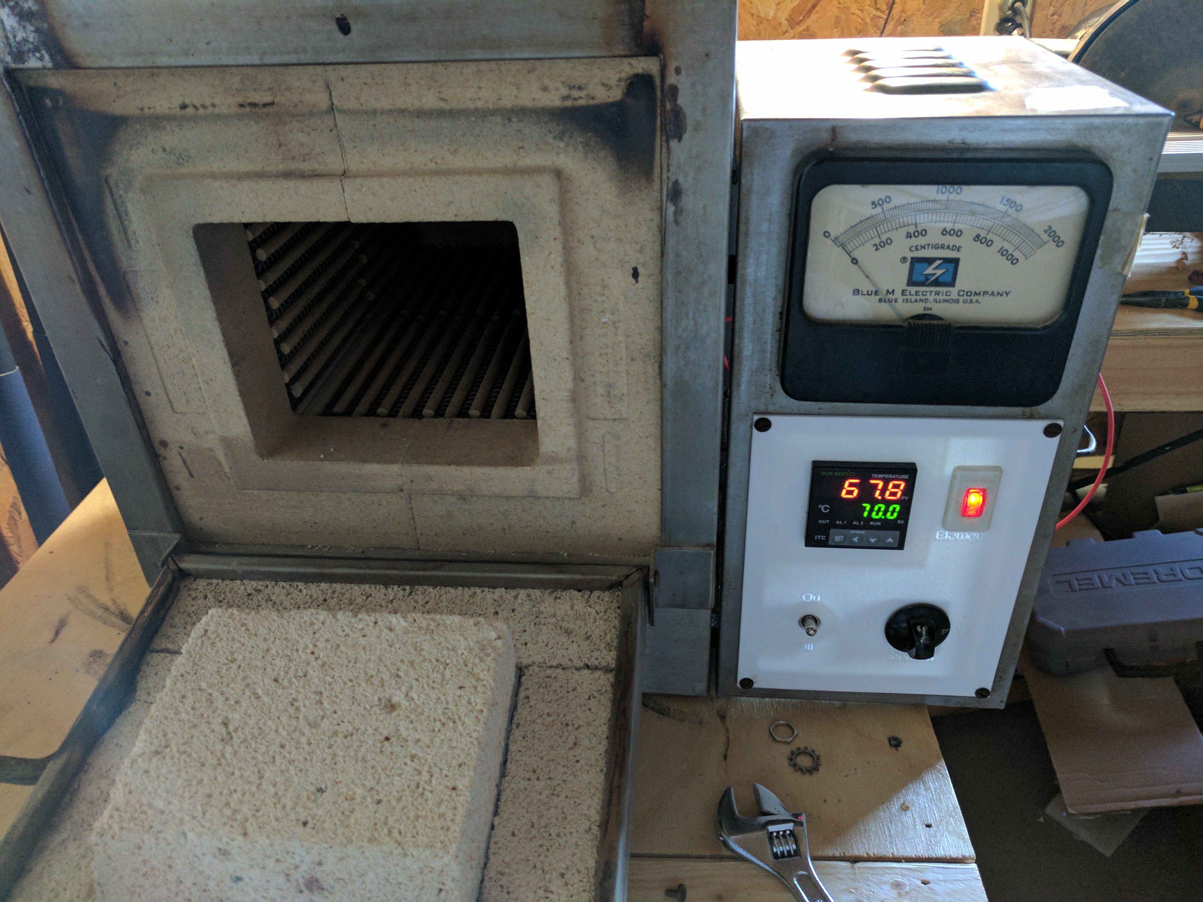
    Things have been a bit slow around here.  Between work travel, personal events on weekends and waiting for components to arrive, not a whole lot has been happening on the MakerFoundry.  My schedule should free up next month, so I'm hopeful updates will resume with good frequency then.

    In the meantime, I upgraded the temperature controller on my muffle furnace as a small-yet-useful project.

    Fair warning: my main laptop has gone to the great scrapheap in the sky, so I'm stuck with potato camera photos and minimal editing for the foreseeable future.  Sorry :(

    Read more »

  • Growing some Oxide

    polyfractal07/12/2017 at 04:45 4 comments

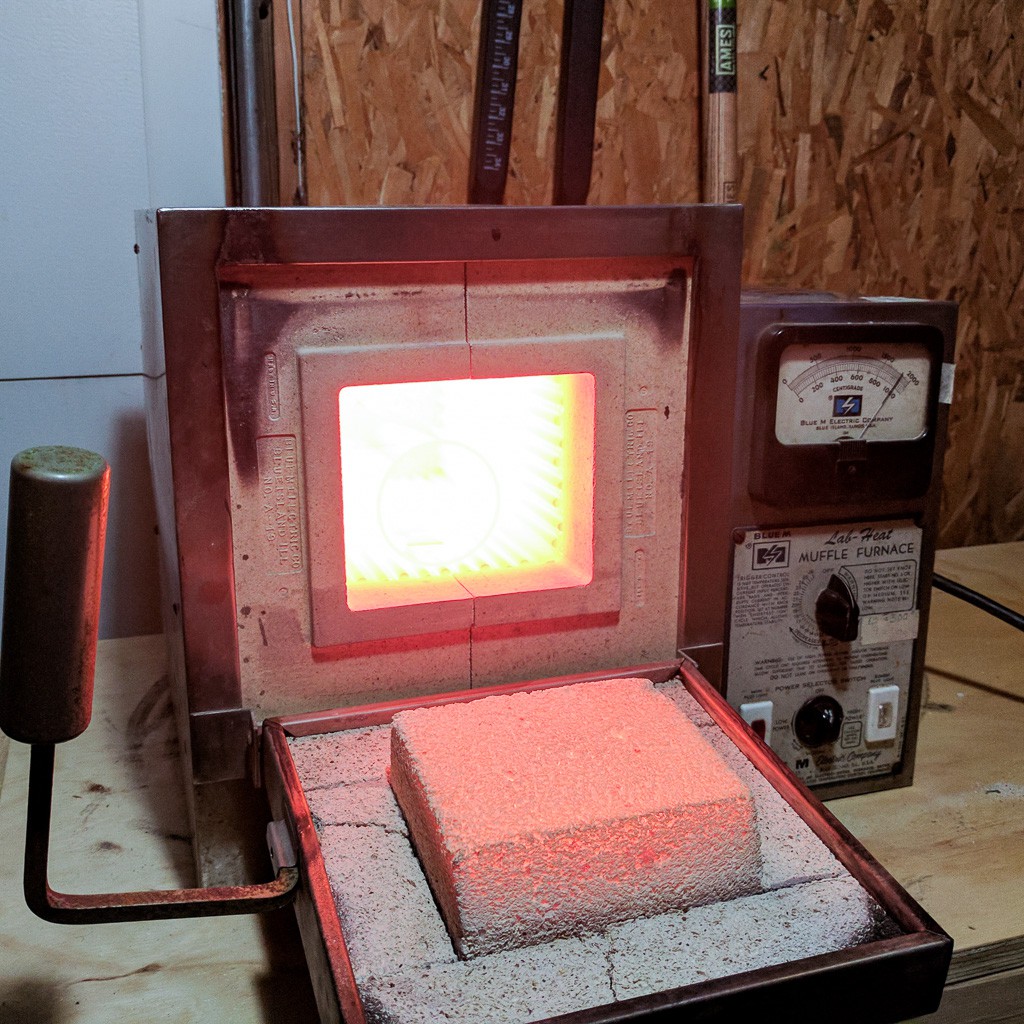
    The best part about projects like this is getting to scrounge up new-to-you toys to play with. In this case, I get to play with a 1000C bench furnace. I mean, just look at that baby glowing. Fun!

    Read more »

  • Mystery somewhat solved

    polyfractal07/03/2017 at 15:00 8 comments

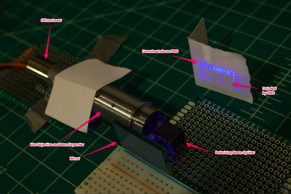
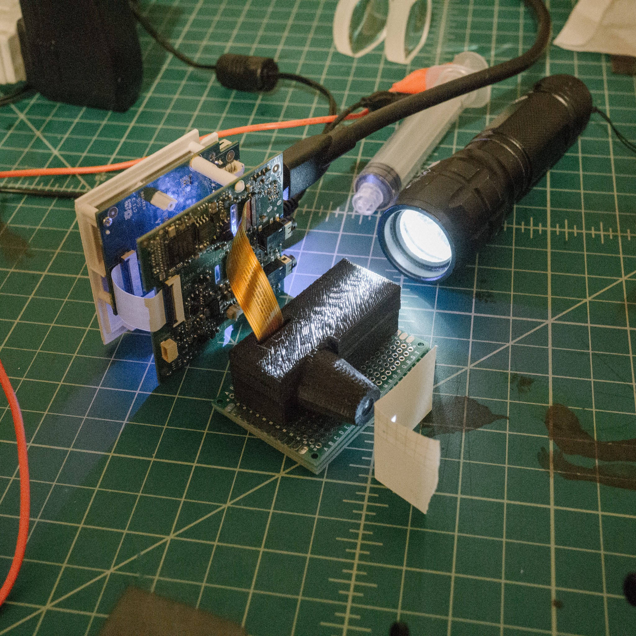
    I pulled apart the various components and tested them individually, and I'm fairly convinced the problem is the polarizing beam splitter. If I replace the LCoS with a simple mirror and remove all the other components, I see this:

    Tl;dr: not good news. :/

    Read more »

  • Good news, bad news

    polyfractal07/02/2017 at 11:00 1 comment

    Did you see this update coming? I did. Nothing ever works r̶i̶g̶h̶t̶ ̶t̶h̶e̶ ̶f̶i̶r̶s̶t̶ ̶t̶i̶m̶e̶ ever. :)

    Read more »

  • Optical assembly printed!

    polyfractal06/30/2017 at 21:15 4 comments

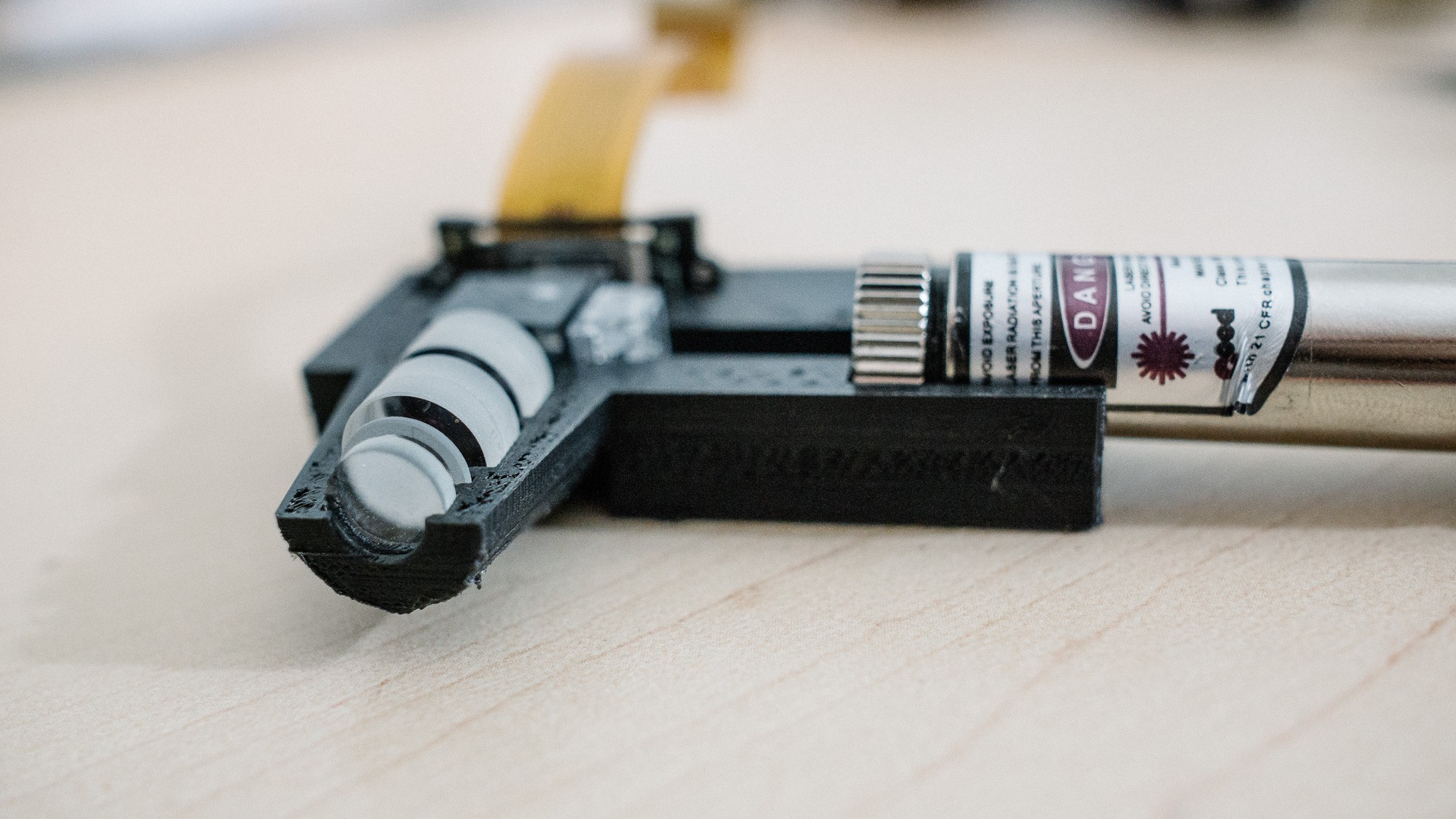
    Four revisions later (fiddling with printing tolerances, and poorly measured components), I have a complete optical assembly with the laser, objective and LCoS system.

    Next step is to print the top half and run some tests to see if it works!

  • Printing time!

    polyfractal06/28/2017 at 00:25 0 comments

    Fingers crossed! :) Some of the features are quite small, so I'll be printing this with my printers best settings (0.2mm nozzle @ 0.05mm layer height)

  • Final light engine deconstruction

    polyfractal06/27/2017 at 14:59 0 comments

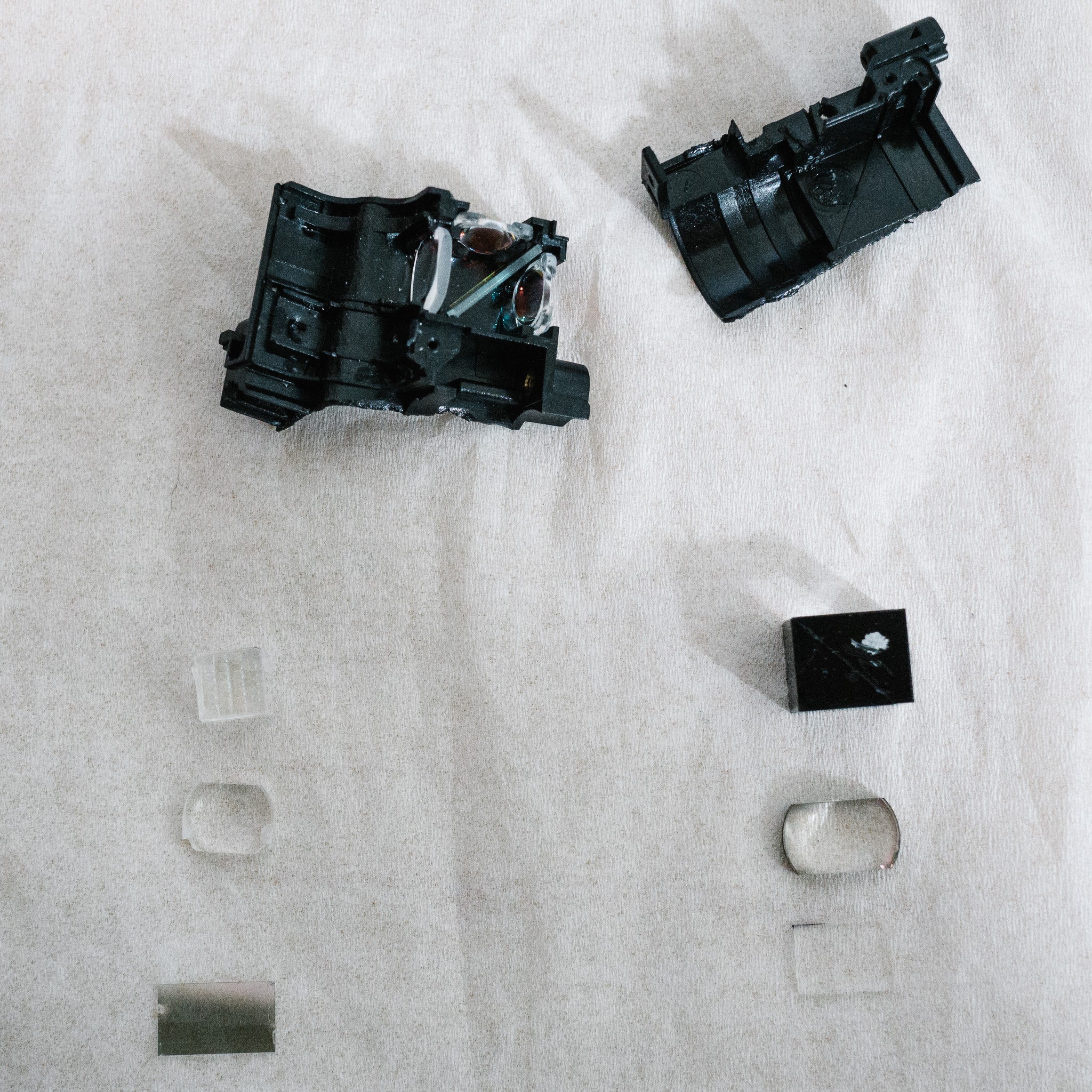
    Welp. The deed is done; the final components of the light engine have been removed and measured... and the housing was destroyed in the process.

    After removing and measuring the components, I started playing around with them and discovered a few interesting, unexpected things.

    Read more »

  • Let the modeling begin

    polyfractal06/23/2017 at 13:44 0 comments

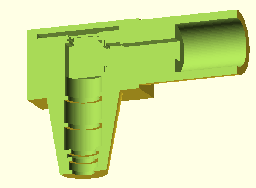
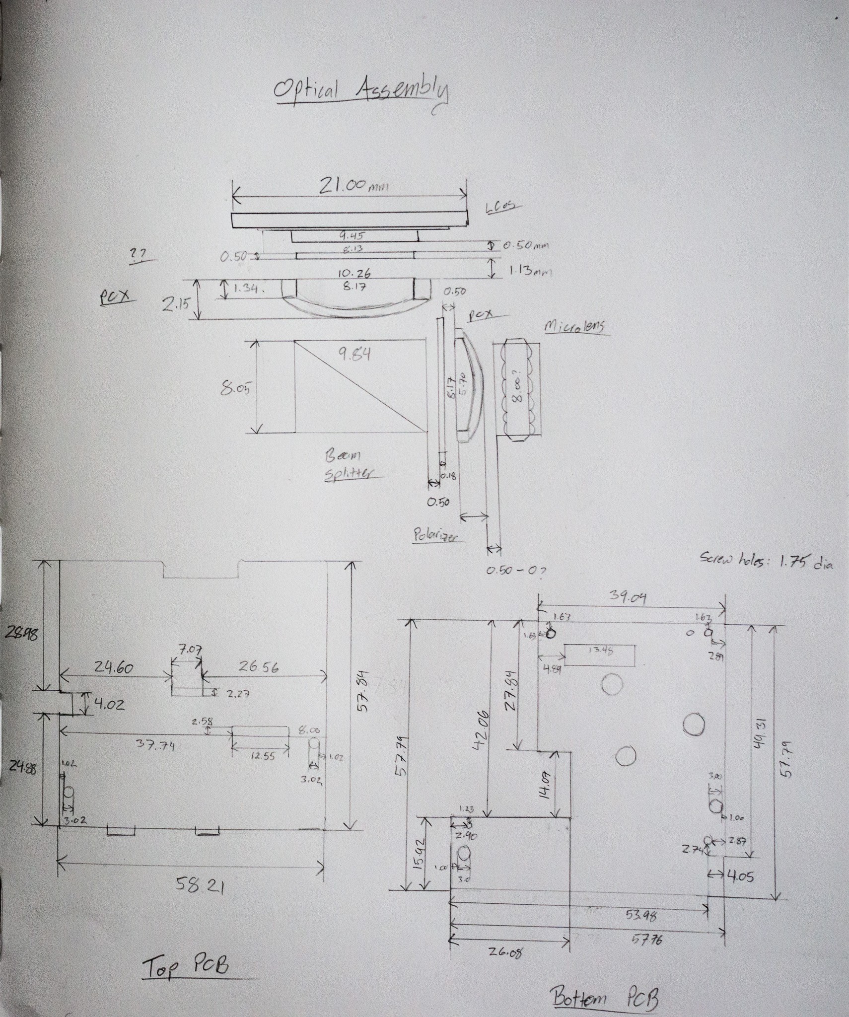
    I've decided to try "Option #2" with regards to the light engine's optical assembly; namely, pulling the components and designing a single, monolithic print to house everything (PCBs, light engine, microscope objective).

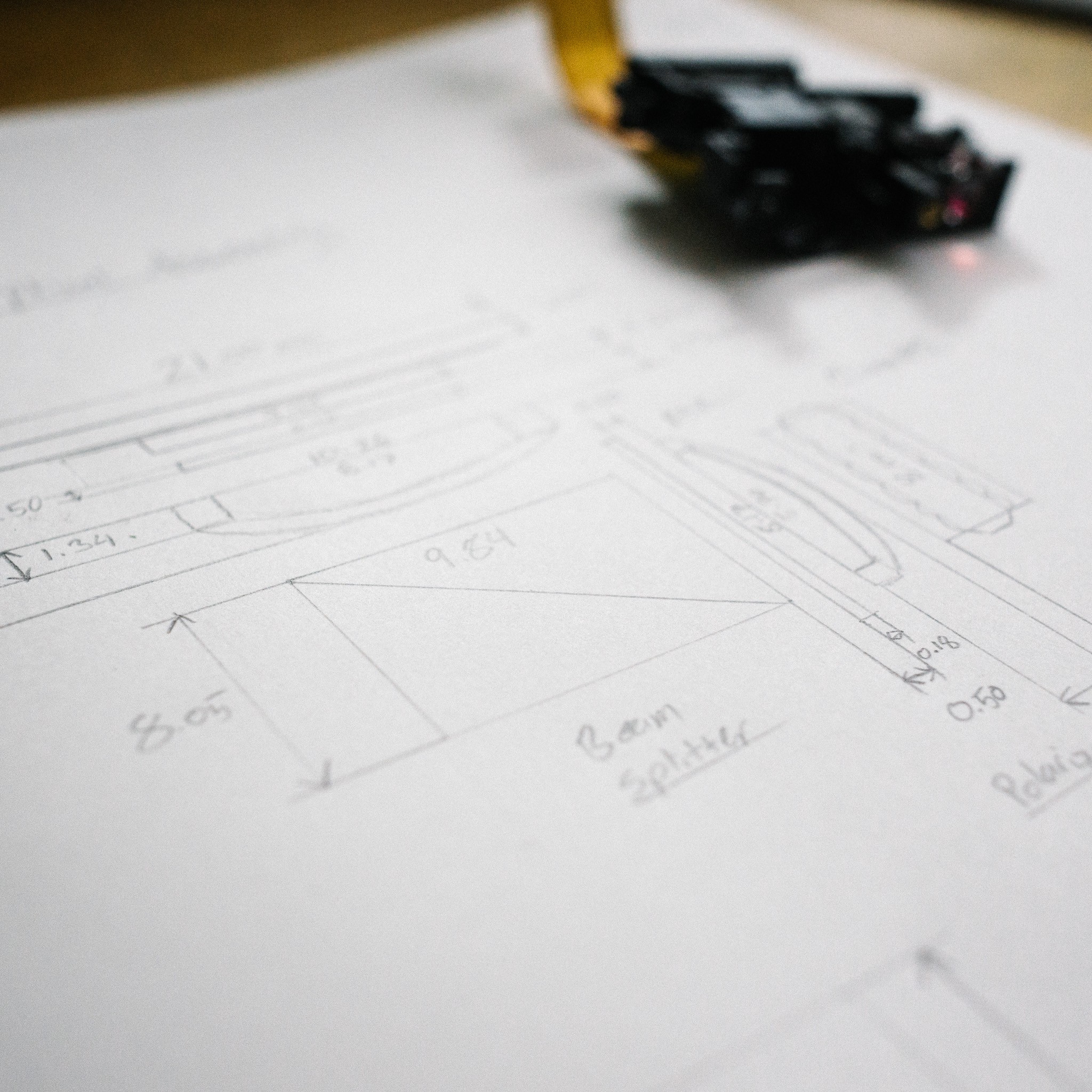
    Measured all the inter-element dimensions before I start pulling components, just to make sure I have a record of the "official" setup. I'm going to try removing the PCX lenses from the overall configuration so I don't think I'll need these dimensions, but it can't hurt to have. I also took down the PCB dimensions so I can build a proper housing instead of just using double-sided tape :)

    Time to dust off OpenSCAD and start modeling the enclosure!

View all 18 project logs

Enjoy this project?

Share

Discussions

anonynous wrote 09/29/2020 at 07:08 point

You have depicted extremely wonderful things about the Dartmoor in this article. You should visit sentencechecker.org/someone-to-correct-my-sentence/ to get more details about writing. Truly, I am totally keen on observing this lovely city now.

  Are you sure? yes | no

anonynous wrote 09/29/2020 at 07:04 point

After quite a while, the greatest update of the Pro Cycling Manager will be presented. I often visit nounchecker.com/try-our-professional-noun-checker  for more informative ideas. I am now feeling too amped up for seeing the most recent highlights.

  Are you sure? yes | no

polyfractal wrote 07/19/2017 at 18:56 point

Well that's nifty, thanks for the link!  Will dig through the project logs.

  Are you sure? yes | no

Gravis wrote 07/01/2017 at 17:46 point

Do you have any plans for how to align the array of exposures needed to compose an IC design?

  Are you sure? yes | no

polyfractal wrote 07/02/2017 at 10:28 point

Yeah, I have a series of plans, ranging from easy to hard. :)  I'm going to first try simple end-stop switches and see how consistent xy traversal is with the geared motors.  Given the feature sizes I'm working on, it may be sufficent.

If that doesn't work, I have some beam splitters that I'll use to add a second light path to the optical assembly, which will allow mounting a camera.  Basically, I'll turn on bright white light and use it as a microscope, align, and then turn off the camera/light and use the laser to expose.

If optical alignment isn't sufficient (I think it should be... optical alignment was used throughout the 70s and I think is still used today in some larger fabs), I was considering setting up a simple interferometer system to track xy position.  Would be irritating and tedious, but not out impossible for a hobbyist. 

  Are you sure? yes | no

Dylan Brophy wrote 06/27/2017 at 21:34 point

I would love to see this project work well because I want to design my own chips.

  Are you sure? yes | no

polyfractal wrote 07/02/2017 at 10:23 point

You and me both!  Even simple discrete circuits (like a 555 timer replica) would be pretty awesome imo :)

  Are you sure? yes | no

Dylan Brophy wrote 07/02/2017 at 17:20 point

Yes, that would be so cool!  I have designed my own CPUs, and those I really would like in a chip instead of an FPGA.  Or video generators for making graphics...  Hey, and what about chip packages? To put the die in?

  Are you sure? yes | no

polyfractal wrote 07/02/2017 at 23:16 point

@Dylan Brophy No immediate plans, figure I'll sort it out when I get there.  I was somewhat hoping that the xy stage would be accurate enough that I can stitch together multiple reticules.  Even if it isn't micron-accurate, if I can stitch with 50-100um accuracy I think I can use secondary exposures around the die to build large pads, then use silver epoxy or solder balls.

I wasn't going to mess with packaging, probably just bond them directly to a board and epoxy over the whole mess (assuming it ever gets to a working stage), like chip-on-board packaging.

Wire bonders are somewhat reasonable on eBay, so that may be an option too. 

  Are you sure? yes | no

Dylan Brophy wrote 07/02/2017 at 23:54 point

@polyfractal yea, I looked around for bare DIP40 packages after posting the comment, and I can't find any.  I mean, I didn't expect to, but it would have been cool.

  Are you sure? yes | no

polyfractal wrote 07/03/2017 at 11:51 point

@Dylan Brophy Yep, that echos my findings too :(  You can buy bulk ceramic packages from businesses like Kyocera, but I haven't found anyone that sells packages in small quantities.  There are prototyping houses (http://www.europractice-ic.com/prototyping_packaging.phphttp://www.icproto.com/cap-ic-packages.html, etc) that will bond and assemble small quantities for a somewhat-reasonable price, so that may be an option.

  Are you sure? yes | no

[deleted]

[this comment has been deleted]

polyfractal wrote 06/20/2017 at 22:42 point

Thanks!  Right now, I think the best support is just to keep following updates and chime in if you have any knowledge/suggestions.  I'm going to quickly be hitting the edge of my knowledge, and expect to have a lot of open questions as things progress, especially once I start building the xy translation stage.  Having people around to discuss problems with is super helpful!

  Are you sure? yes | no

Jarrett wrote 06/06/2017 at 17:21 point

Suddenly, I have a burning desire to learn optics and build a selective PCB exposure box.

Your project logs are great. Well written and accessible to the lay-person.

  Are you sure? yes | no

polyfractal wrote 06/06/2017 at 20:19 point

Thanks! Glad you've enjoyed the logs so far. It's going to be a wild and bumpy ride as I learn everything, so I figured writing detailed logs would double as my lab notebook :)  I also personally find it easier to understand a topic after having worked through how to explain it.

I bet a PCB exposure box would be pretty straightforward! Creating a PCB-sized, in-focus image shouldn't require a ton of fiddling I don't think, since you're working with the projector's original intention to enlarge the image.  It could probably be done with the stock projection lens, but just from my playing around it'd be doable wit two achromat lenses at the right distance.

  Are you sure? yes | no

Similar Projects

Does this project spark your interest?

Become a member to follow this project and never miss any updates