The plan is roughly:
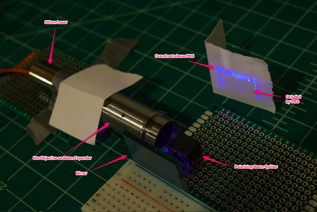
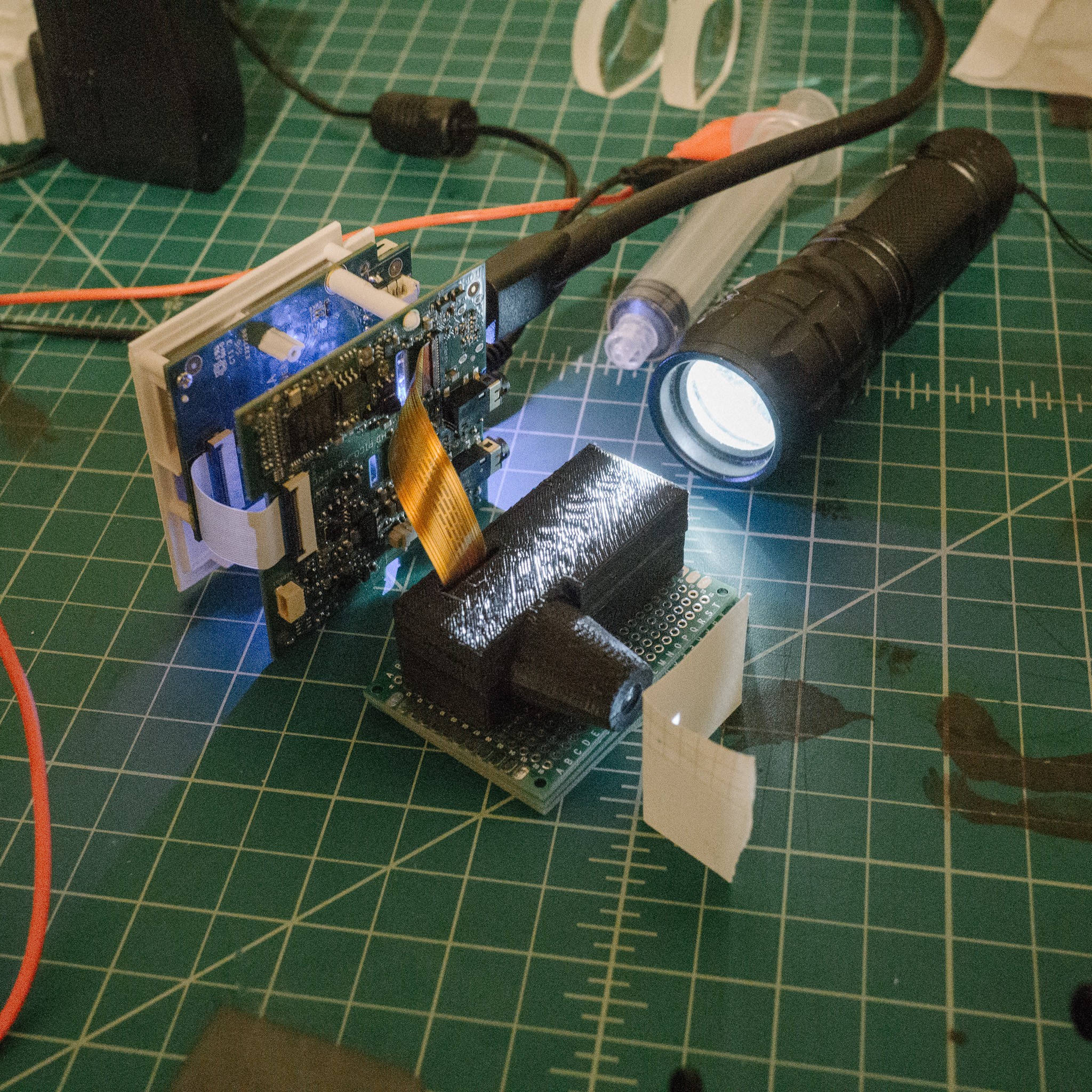
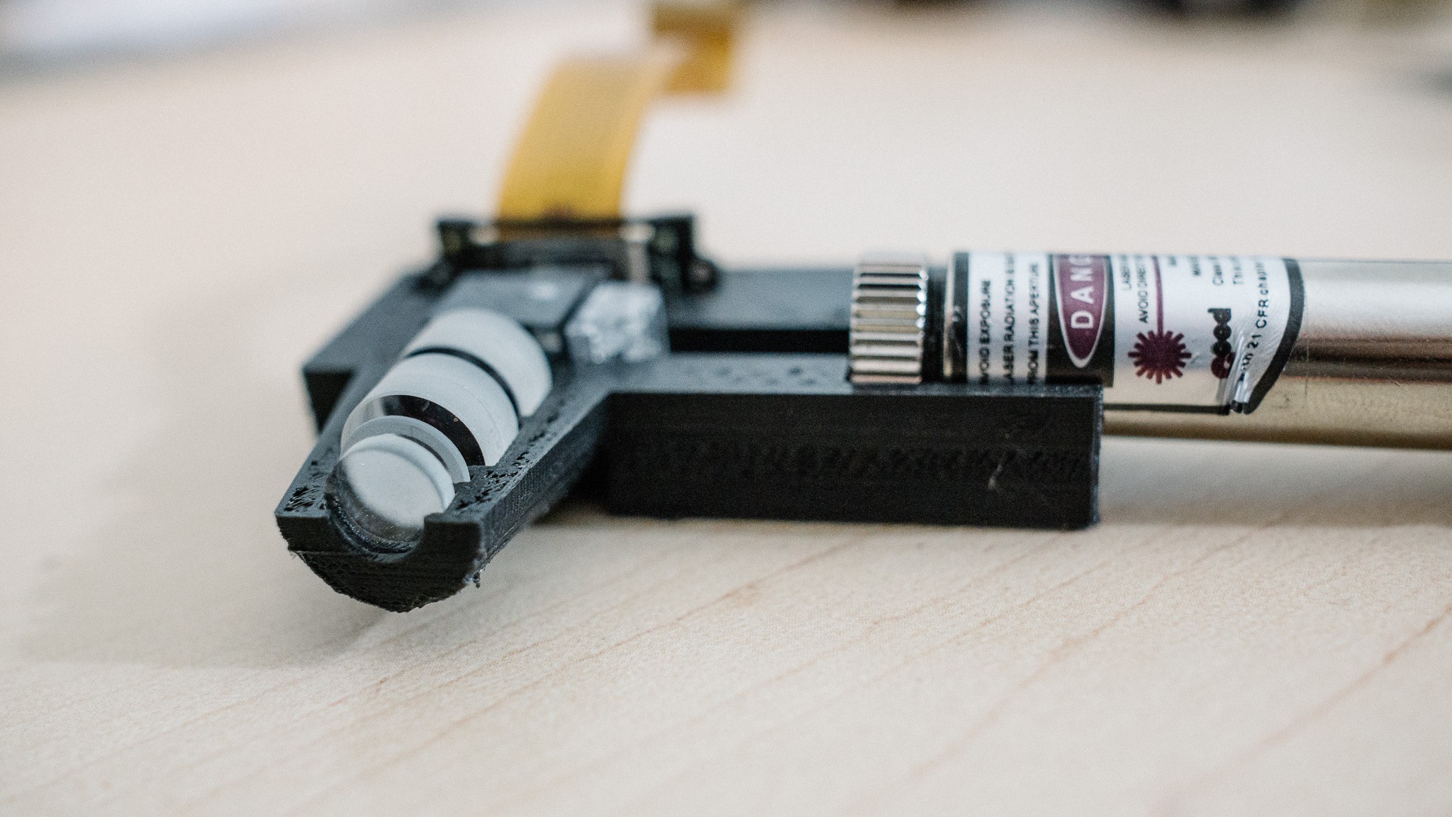
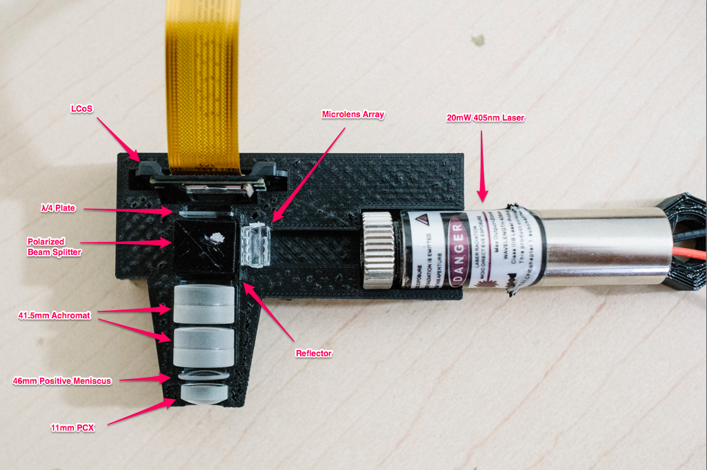
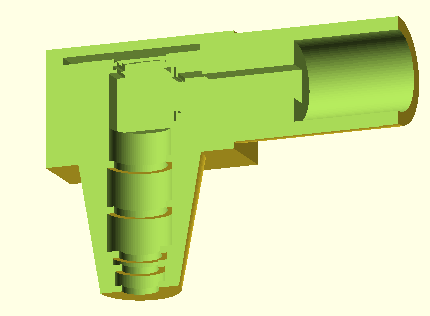
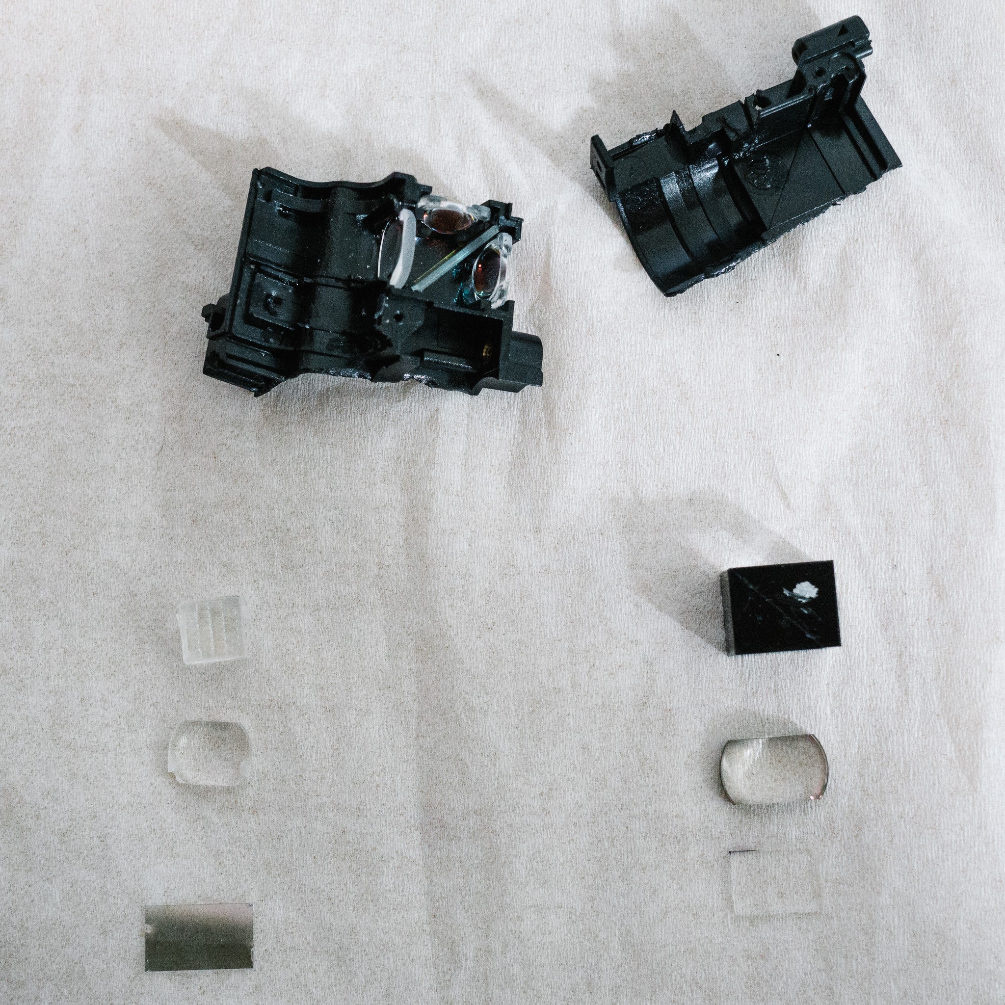
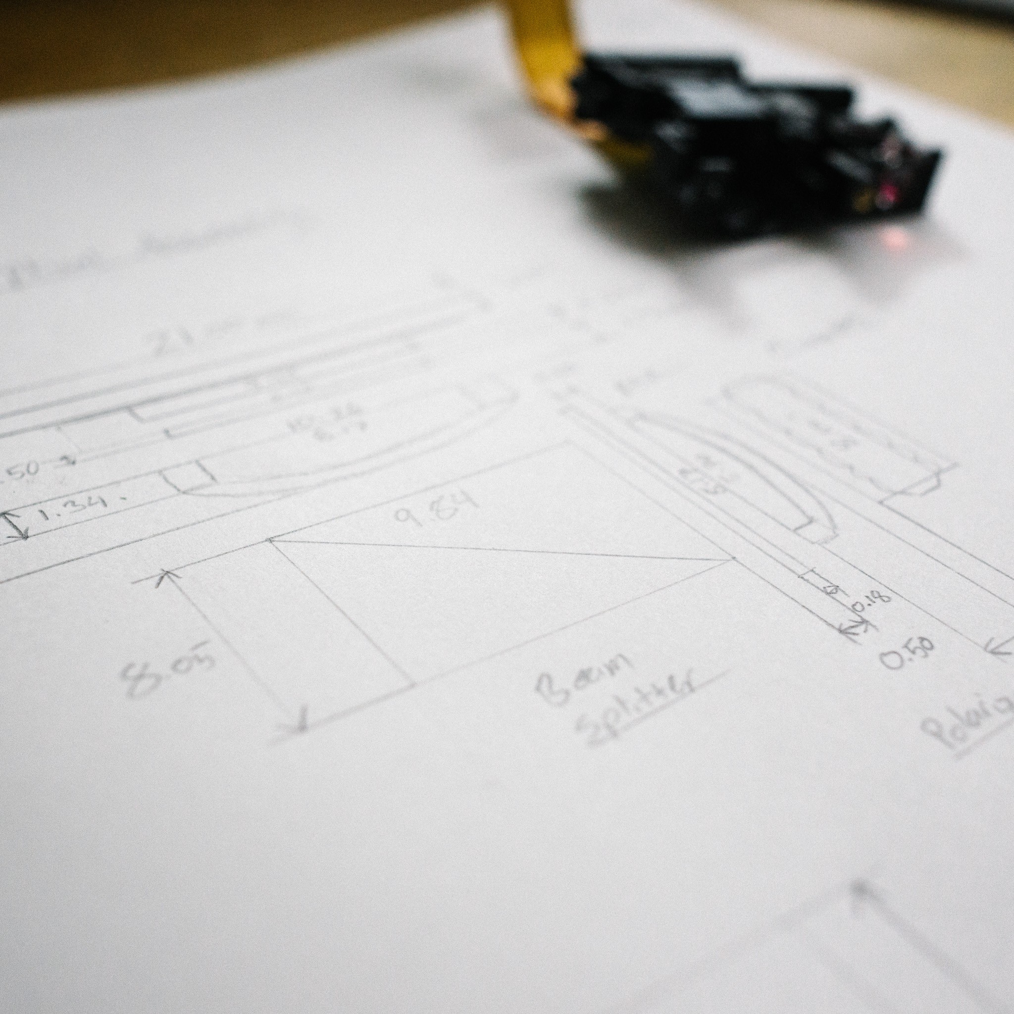
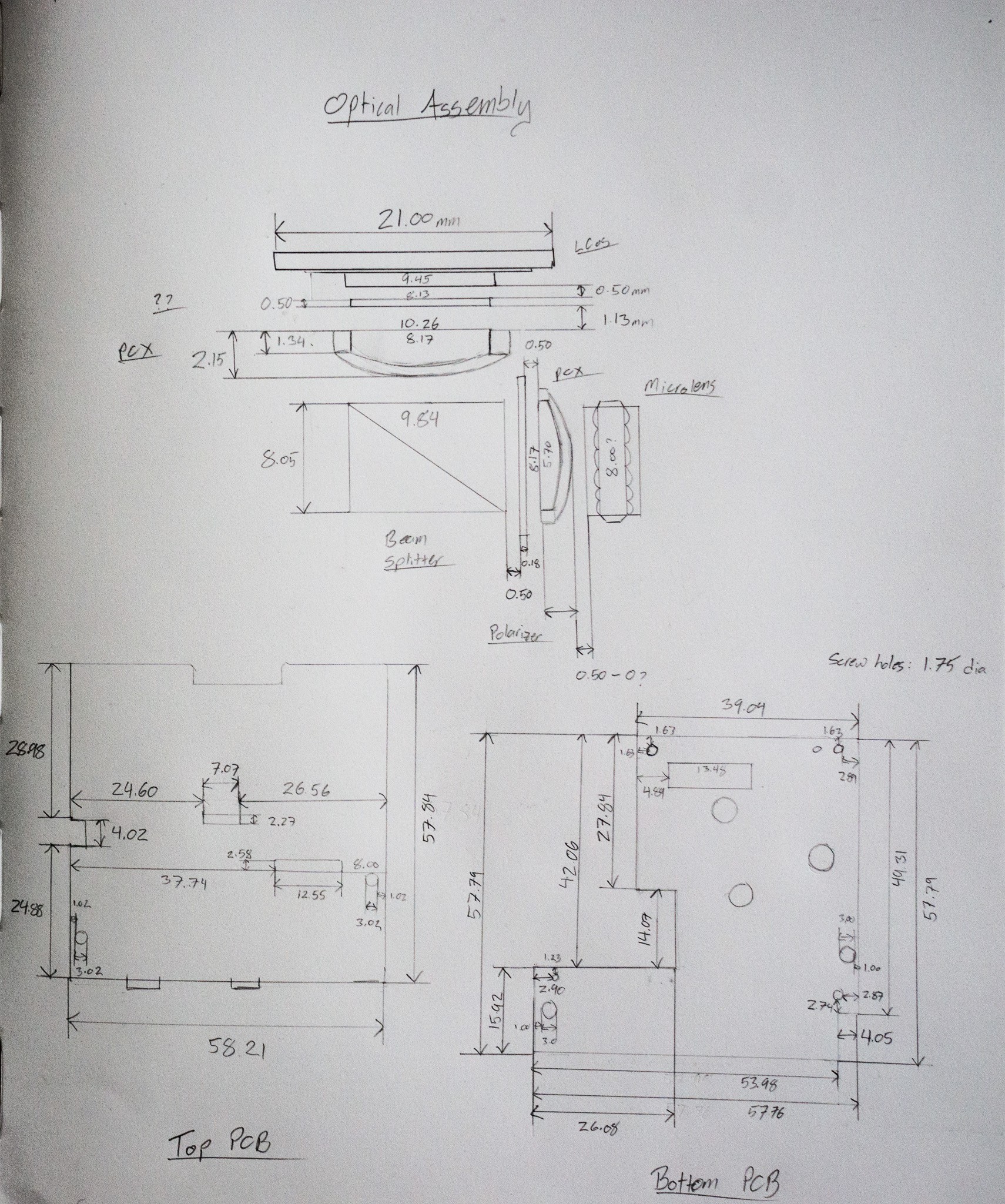
- Modify an LCoS pico projector to perform maskless photolithography using a 405nm laser
- Build a high-precision cartesian plotter for automated positioning and die exposure
- Work my way through IC fab and metallization
- Figure out wire bonding (either via an eBay machine or DIY)
Realistic goal is around 10µm. Theoretical limit of the system is ~600nm due to the 405nm laser wavelength, so I figure an order of magnitude higher is reasonable. It's also the process size of the Intel 4004 in 1971 which seems like a good goal :)
Why Maskless Lithography?
Mask generation is one of the most expensive parts of actual IC fabrication. High-quality photomasks are typically chrome-on-quartz, although cheaper/lower resolution photomasks can be created with regular soda-lime glass and photographic emulsion (e.g. a film negative... but on glass). You could probably even get away with actual film negatives, or laser-printed designs on acrylic.
Considering the target process size (1-10µm) was accomplished in the 1970's, emulsion-based photomasks is probably more historically accurate. :)
That said, there are a lot of challenges to sort out with a mask system (optics, mask production, etc). Many of these also apply to a maskless system using some kind of projector technology... so why not start there?
In addition, a maskless process opens some potentially interesting doors to play with, such as "easy" computational lithography, scanning lithography without having to move the mask, etc.
Why LCoS Pico Projector?
There are four main projection technologies at the moment: digital micromirror devices (DMD, aka DLP), liquid-crystal-on-silicon (LCoS), LCD, and laser. Laser projectors are rather expensive, so we can rule those out right away. Of the rest, LCoS tend to be available cheaply in small "pico projector" packages. There may be other advantages or disadvantages, but price was my main reason.
Why 405nm?
I've read that most photoresists are somewhat sensitive to light at 405nm, which corresponds to the "h-line" on mercury lamps. 405nm is violet light, and just on the edge of visible. Below 400 and you start to reach into UV, which is problematic to work with for many reasons. It requires better optical glass to deal with UV, any plastic in the light path will degrade, LCDs don't enjoy UV light, etc.
So the h-line seemed like a reasonable place to park my wavelength. Finally, you can buy 405nm lasers which will be more convenient to work with than a giant, hot mercury lamp.
IF, however, it turns out that photoresist does not respond to 405nm well, I may investigate "daylight resins" used in some SLA 3D printers. These resins cure with ~500nm (blue) light, and as long as I can find a solvent to dissolve them, may work as a replacement for proper photoresist.
How are you going to build the translation stage?
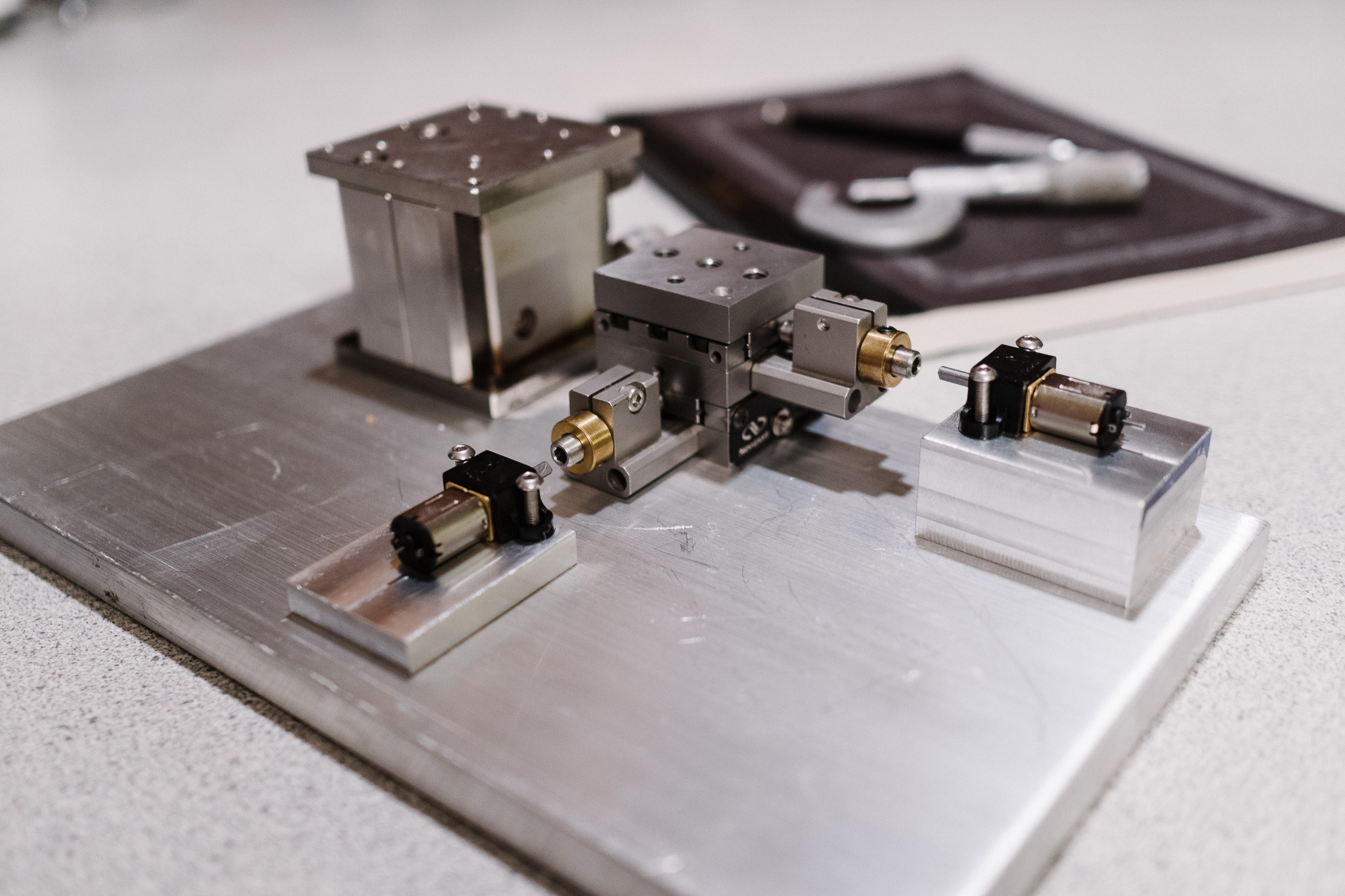
The plan is to use two aluminum CNC z-axis as the basis for the translation stage. These parts are extremely rigid, and geared with a leadscrew that provides 1mm movement per turn. Combined with some high-resolution encoded gear motors (8400 pulses per rotation), I'm hoping to eke out acceptably accurate positioning from the stage
 polyfractal


You have depicted extremely wonderful things about the Dartmoor in this article. You should visit sentencechecker.org/someone-to-correct-my-sentence/ to get more details about writing. Truly, I am totally keen on observing this lovely city now.