 big_red_frog
Right now, go and look at each project log entry for design details, as I work out how best to use hackaday projects, there are presently 5...
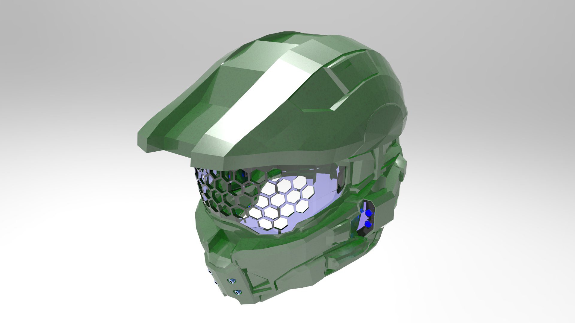
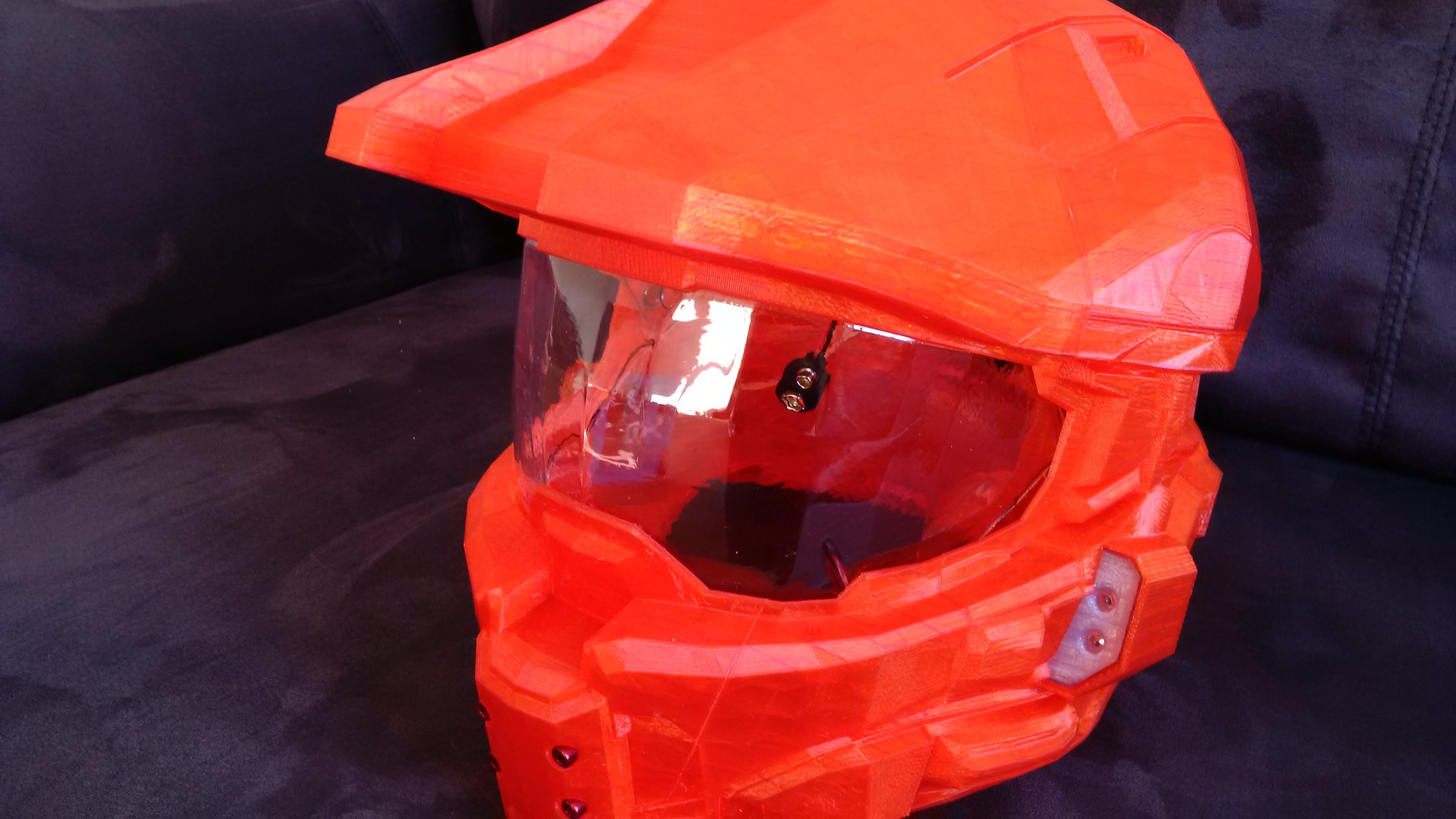
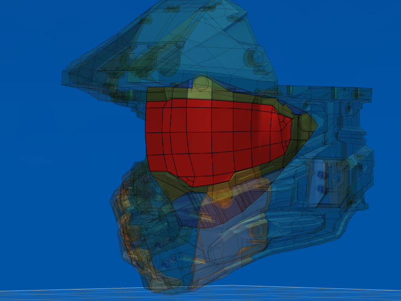
3D printable Halo 4 Master Chief helmet in various sizes...
Already have an account? Log in.
To make the experience fit your profile, pick a username and tell us what interests you.
Right now, go and look at each project log entry for design details, as I work out how best to use hackaday projects, there are presently 5...
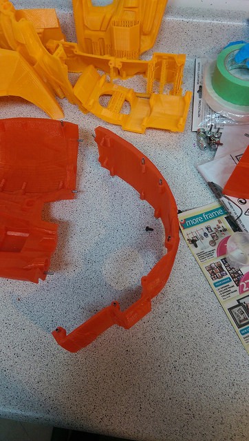
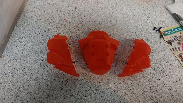
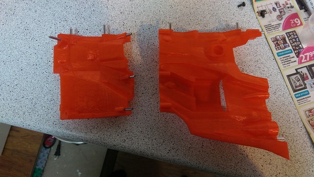
Noting I don't cover magnet inserts in these images, it is just a quick and dirty assembly order for a helmet made with large parts. plastic inserts for back fan and lights are also not shown.
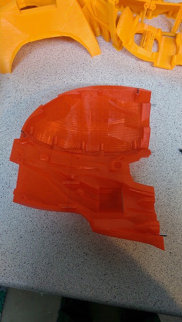
Start with a jowl and rear bottom piece
Attach together
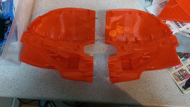
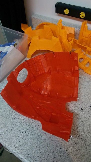
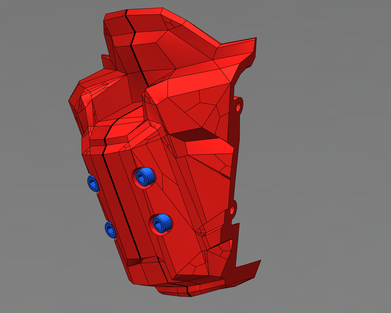
next take a temple and top piece, in this case a printed as a single large part
Attach to form a full side
Repeat for other side
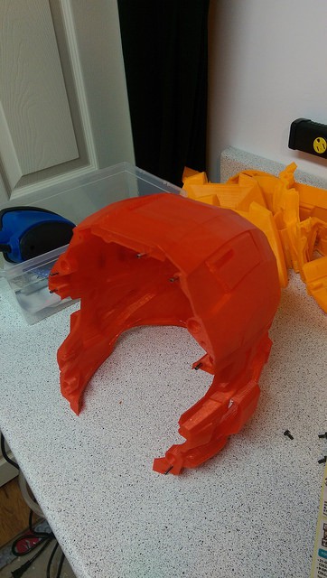
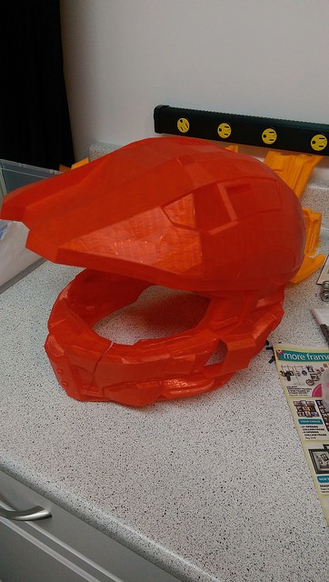
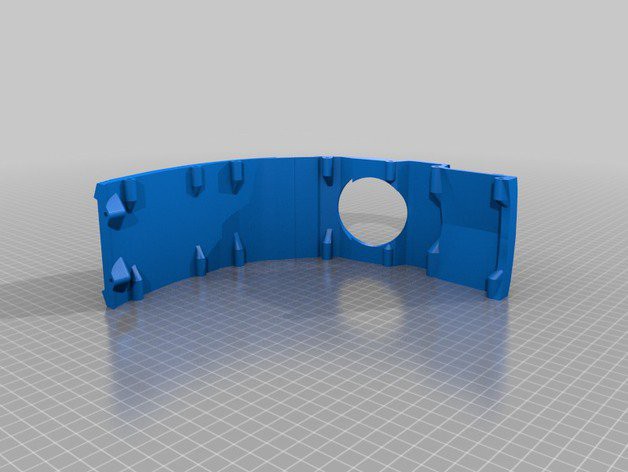
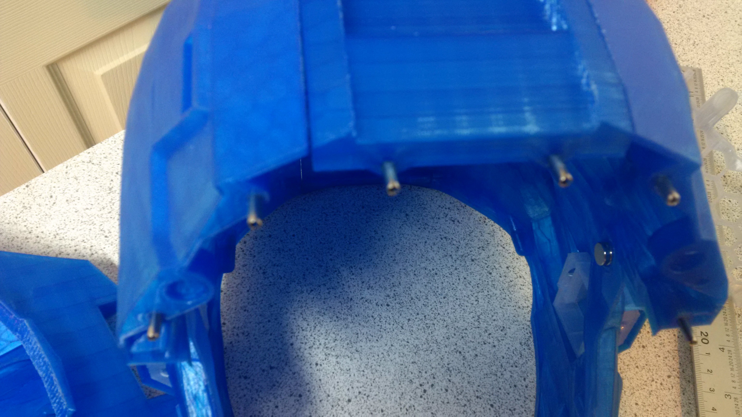
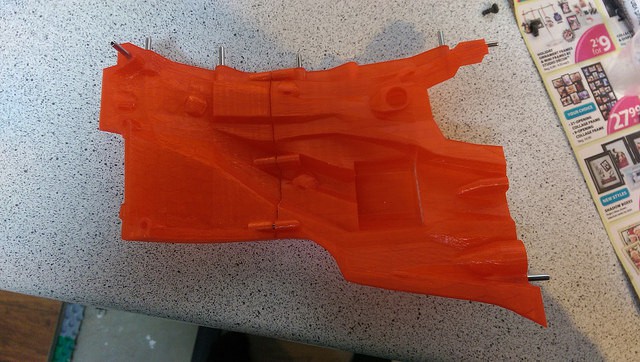
Now take the roof and back piece, ( back fan and back bottom printed as one large piece )
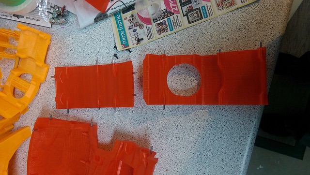
Attach to made one long center piece
Add a full side as assembled previously
Then the other side
Add the peak
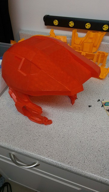
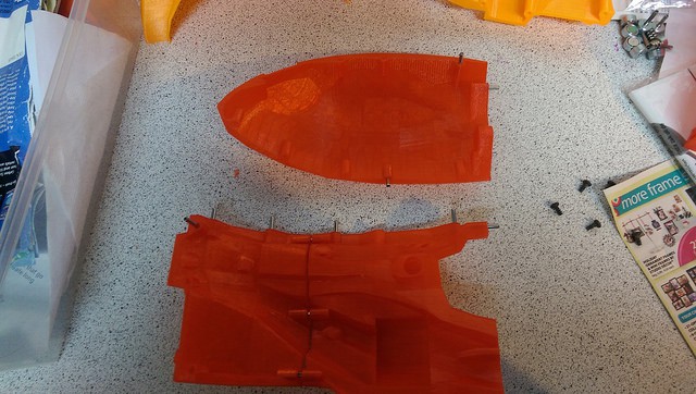
Now take the three chin pieces
Assemble
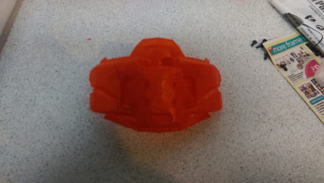
Attach to main helmet
If you are going to print the Size A, you need to understand which extended design parts are available to print...
The size A evolved as I worked the design, there are additional parts available that are either exclusive to the size A or have otherwise been combined into the base model for the size B and C
http://www.thingiverse.com/thing:163439
Perforated Visor for Halo Helmet - want to be able to see through a printed visor?
http://www.thingiverse.com/thing:165110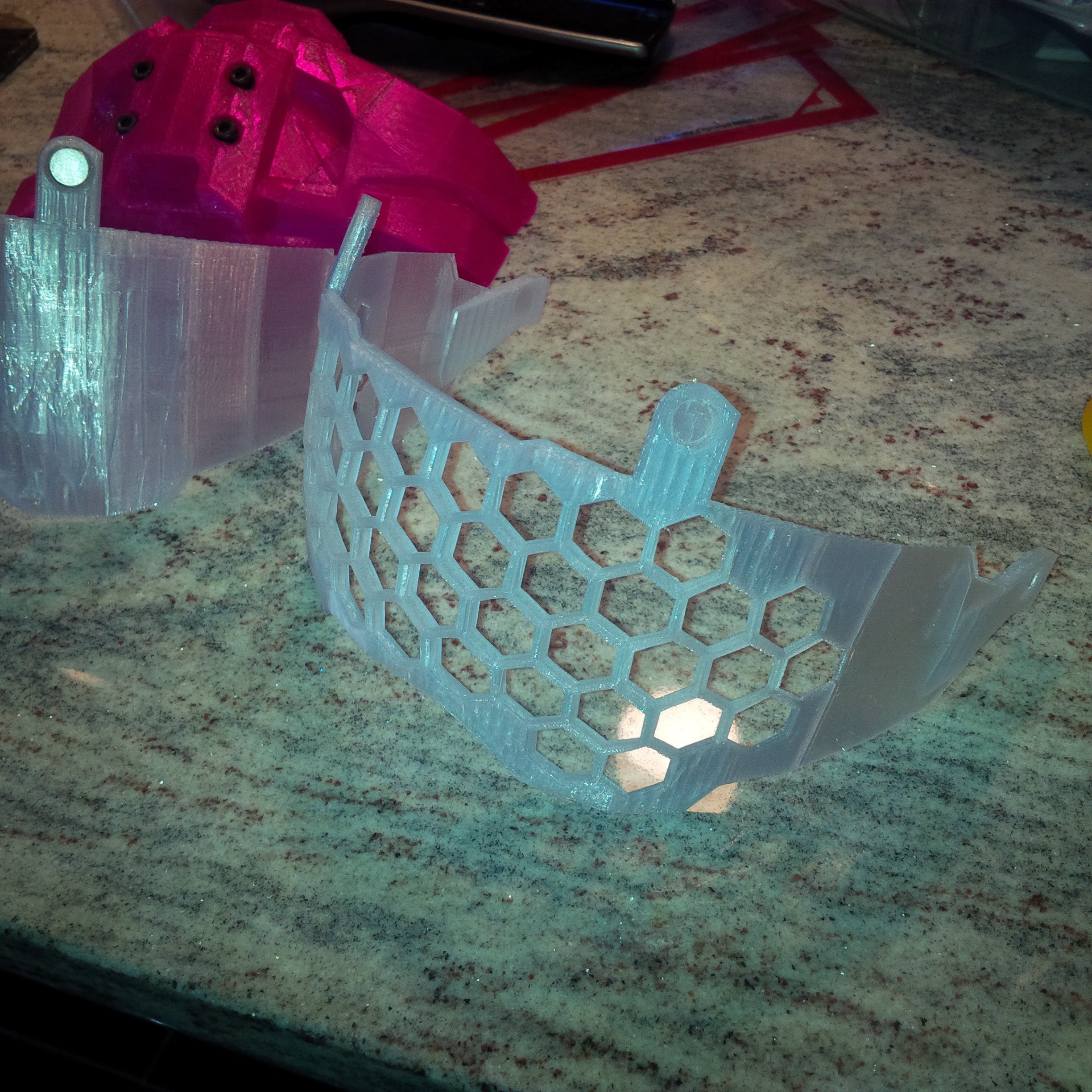
http://www.thingiverse.com/thing:168678
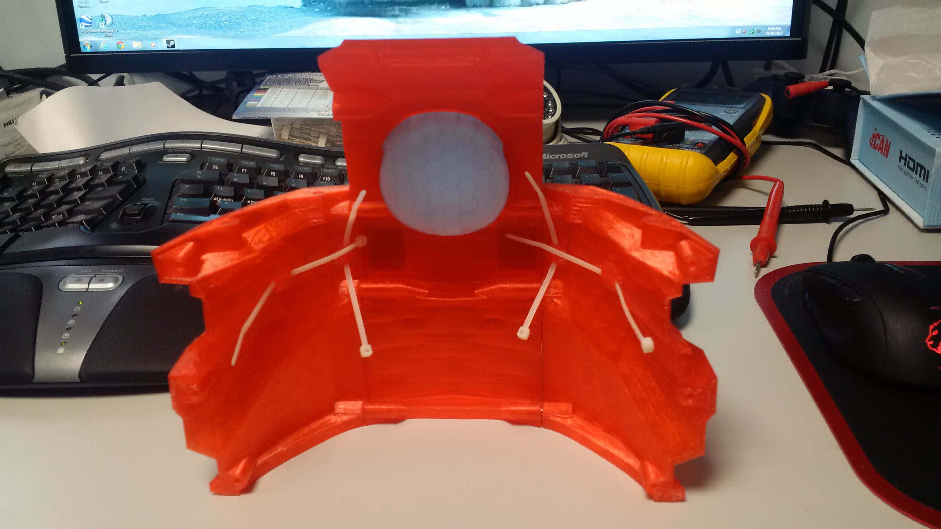
Halo 4 Helmet Full Size A with tiewraps - take control of that wiring harness, with built in tie wrap "warts" in the inside of the model.
http://www.thingiverse.com/thing:169295
http://www.thingiverse.com/thing:171912

Want a PETG vac formed clear visor ready for painting in your favorite metallic?
http://www.thingiverse.com/thing:217267
Print in place tie wrap mount points for wiring guides
http://www.thingiverse.com/thing:169295 and
http://www.thingiverse.com/thing:171912
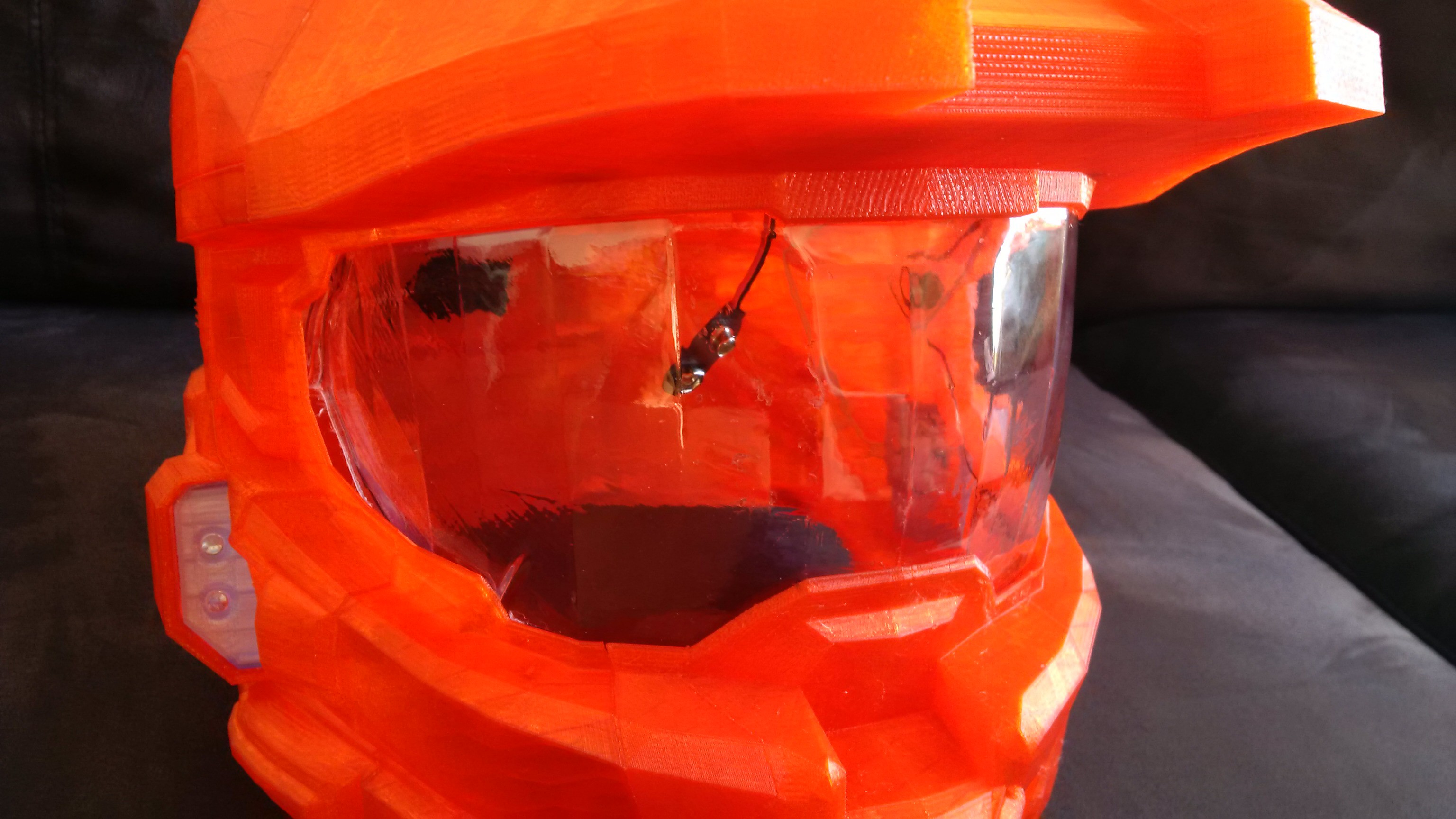
The present lighting circuit is very simple, soldering the resistor in series with each pair of 5mm LEDs. The resistor can sit directly between the LED's themselves, which makes soldering the twisted pins easy.
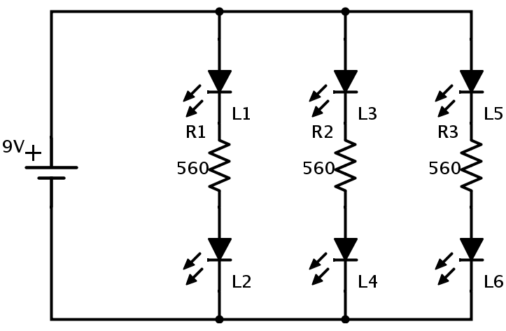
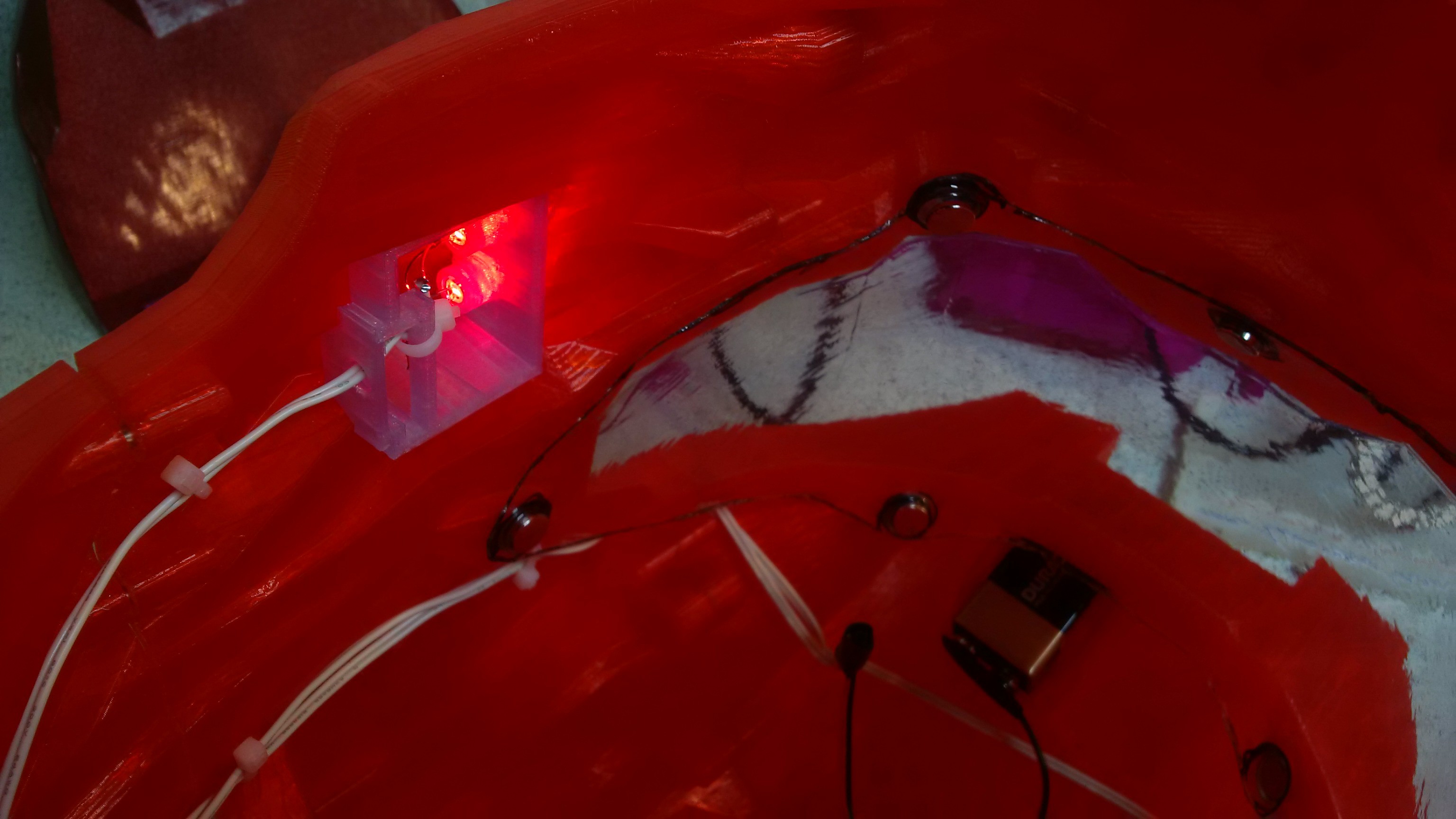
Here are the rear insert LEDs, with contacts taped off. Same combination of two 5mm LED's and a current limiting resistor.
Note all three pairs, 2 Jowls and the rear insert are wired in parallel to the 9 volt.
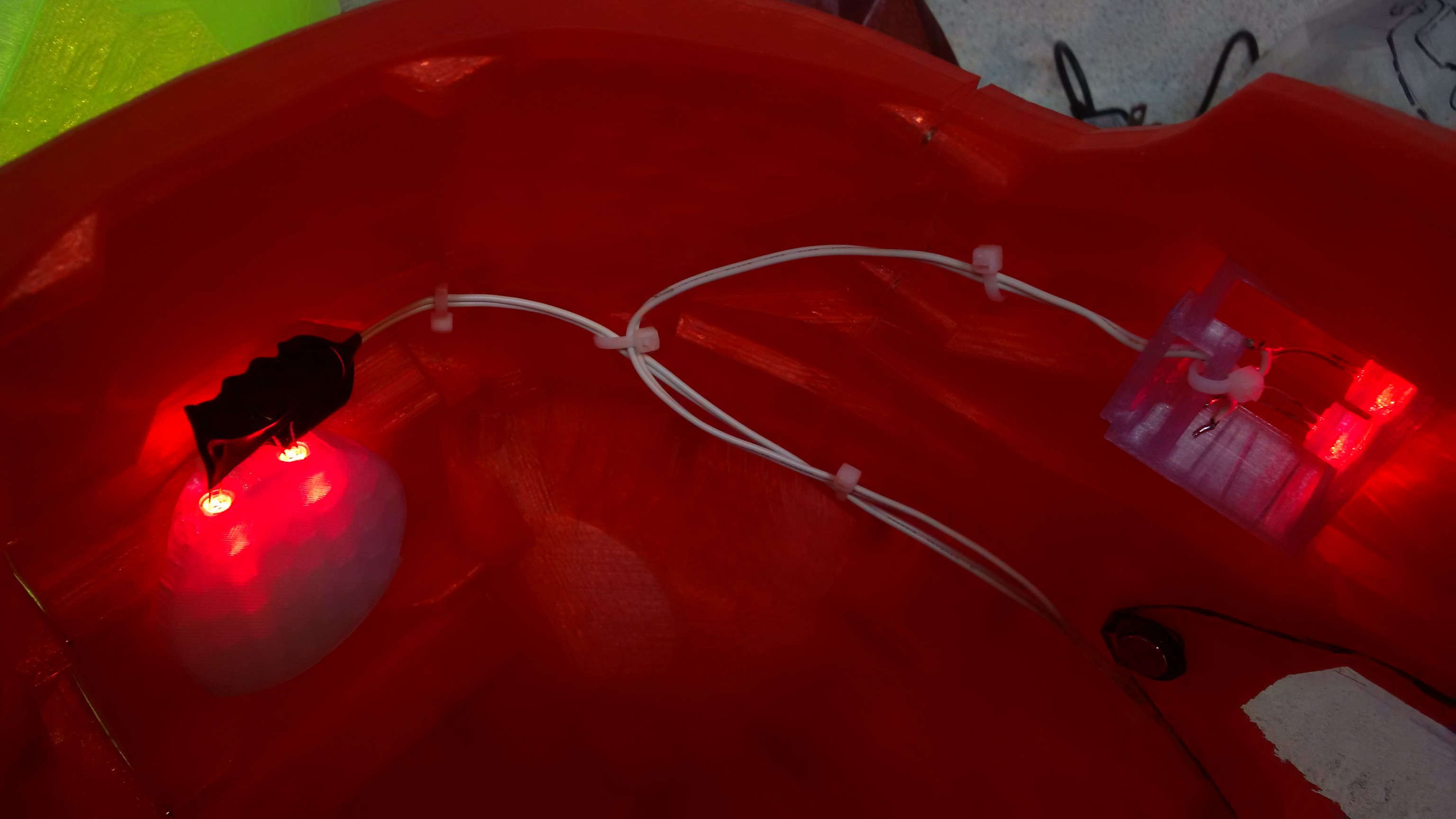 Here is the Jowl on the other side, which wires straight to the peak to join up with the other runs.
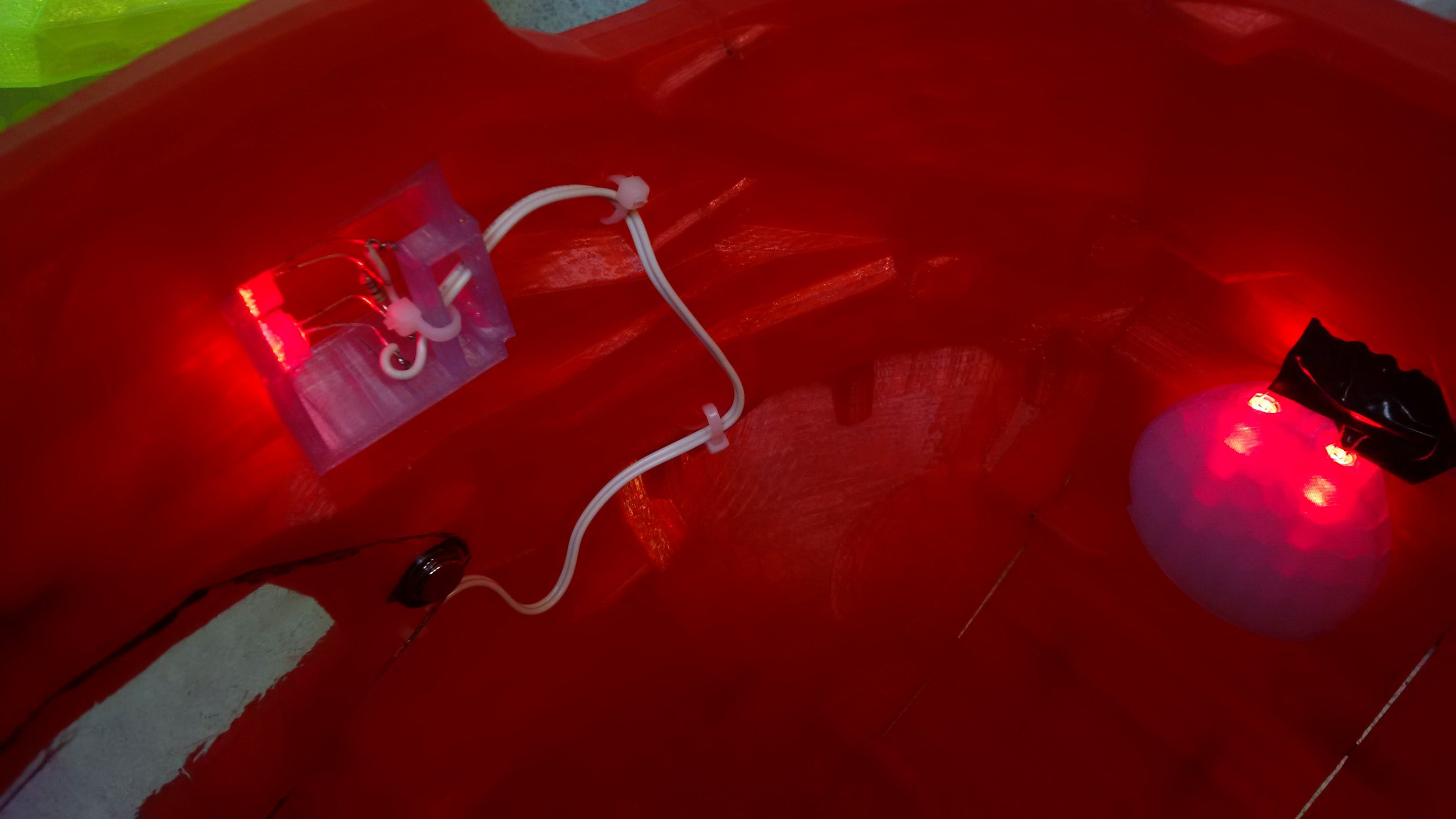 I originally put an in line switch in the design, but it was more trouble than it was worth, and pulling the battery connector off is the preferred form of control at this time...
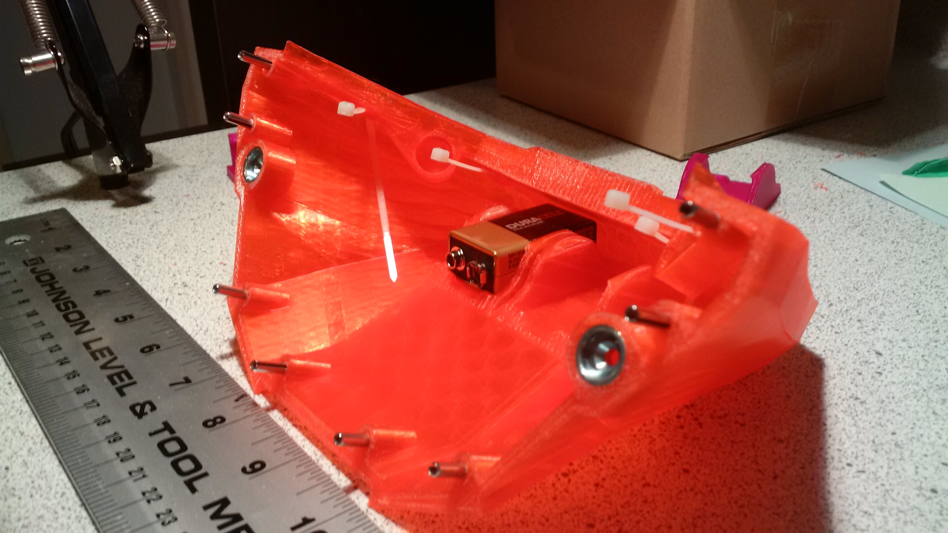
The use of tension pins allows components to be accurately aligned for gluing or in use assembly such as the chin parts.
This also allows you to print split surfaces as flats, which helps.
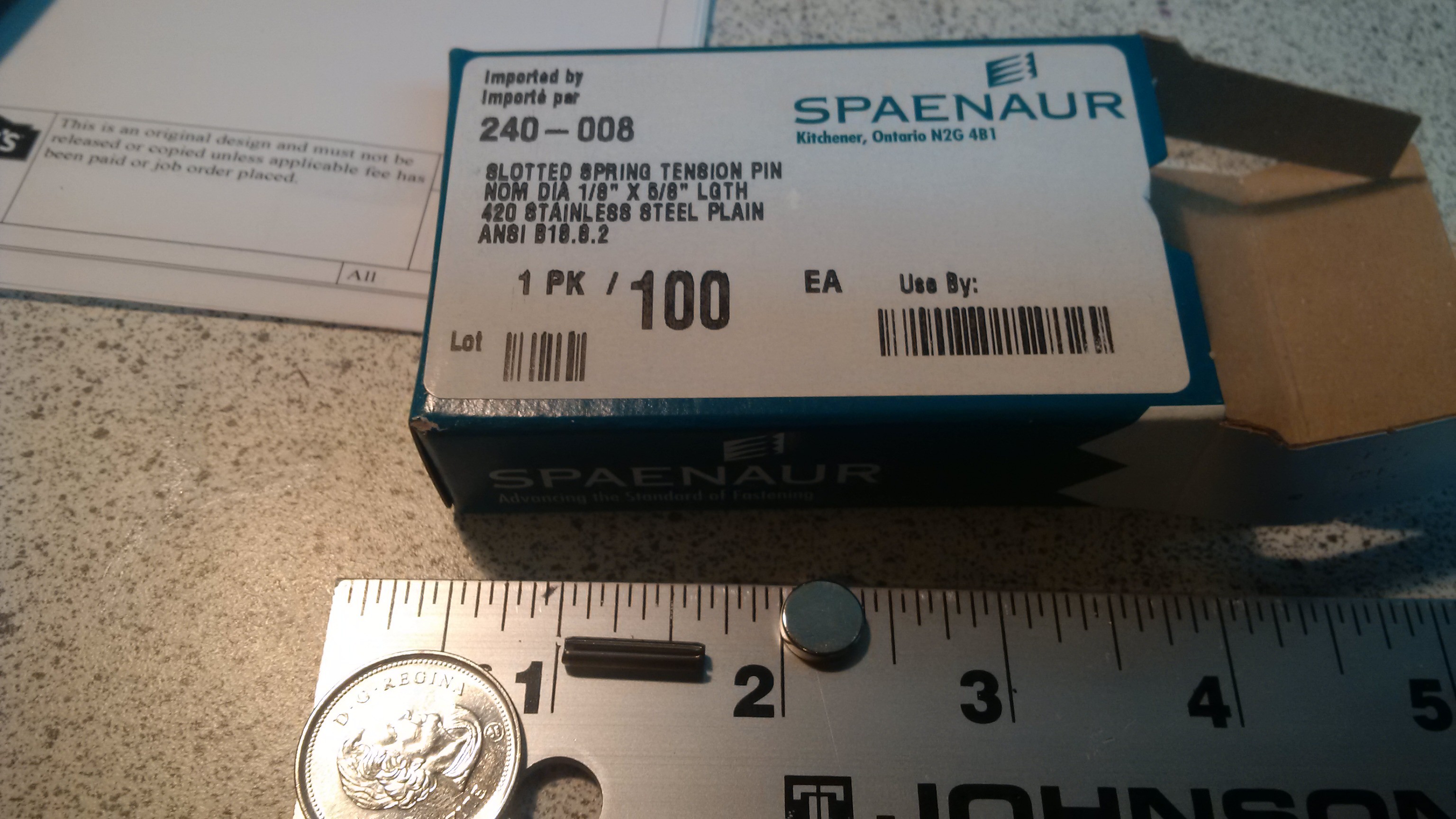
I have used tension pins purely because I knew I could get them. 3mm filament is close enough to 1/8 inch diameter, so you could just as easily cut lengths of such to use, or any other material with a nominal 1/8 diameter.
Two lengths have been used in the various models.
http://www.spaenaur.com/pdf/sectionE/E107.pdf
Size B Medium and Size C child uses 5/8 inch pins throughout, as per
They can also be bought from Amazon, not sure on those prices and delivery though. ( really, find a local hardware supplier, a real one, not a big box store who will happily charge you a dollar for 2! )
5/8 length http://www.amazon.com/Tension-Pin-20-pieces/dp/B00...
Here is a picture of a 5/8 pin next to a magnet and coin for scale, no banana was available at the time.
 When printing with support it is likely that various holes in the model will end up with webbing inside them, if they are horizontal or facing down, that's fine though, the material is intended to be removed, and should give, without damaging the main body.
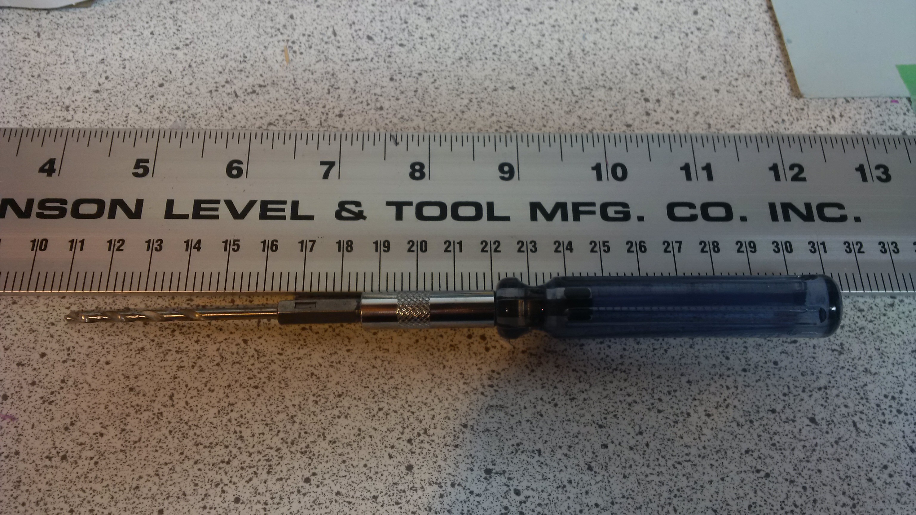
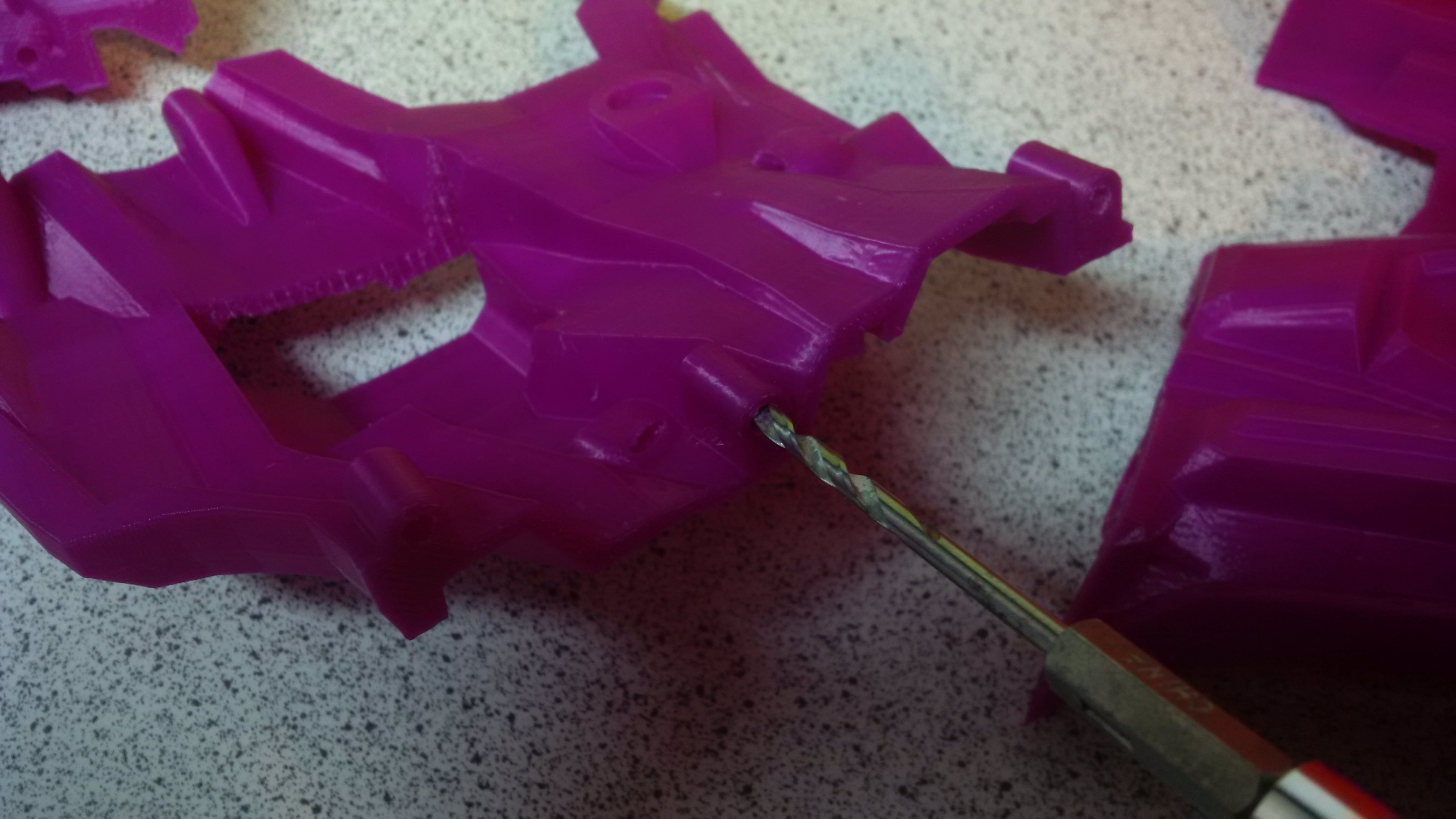
You will need a 1/8 diameter drill bit on a hex mount as per
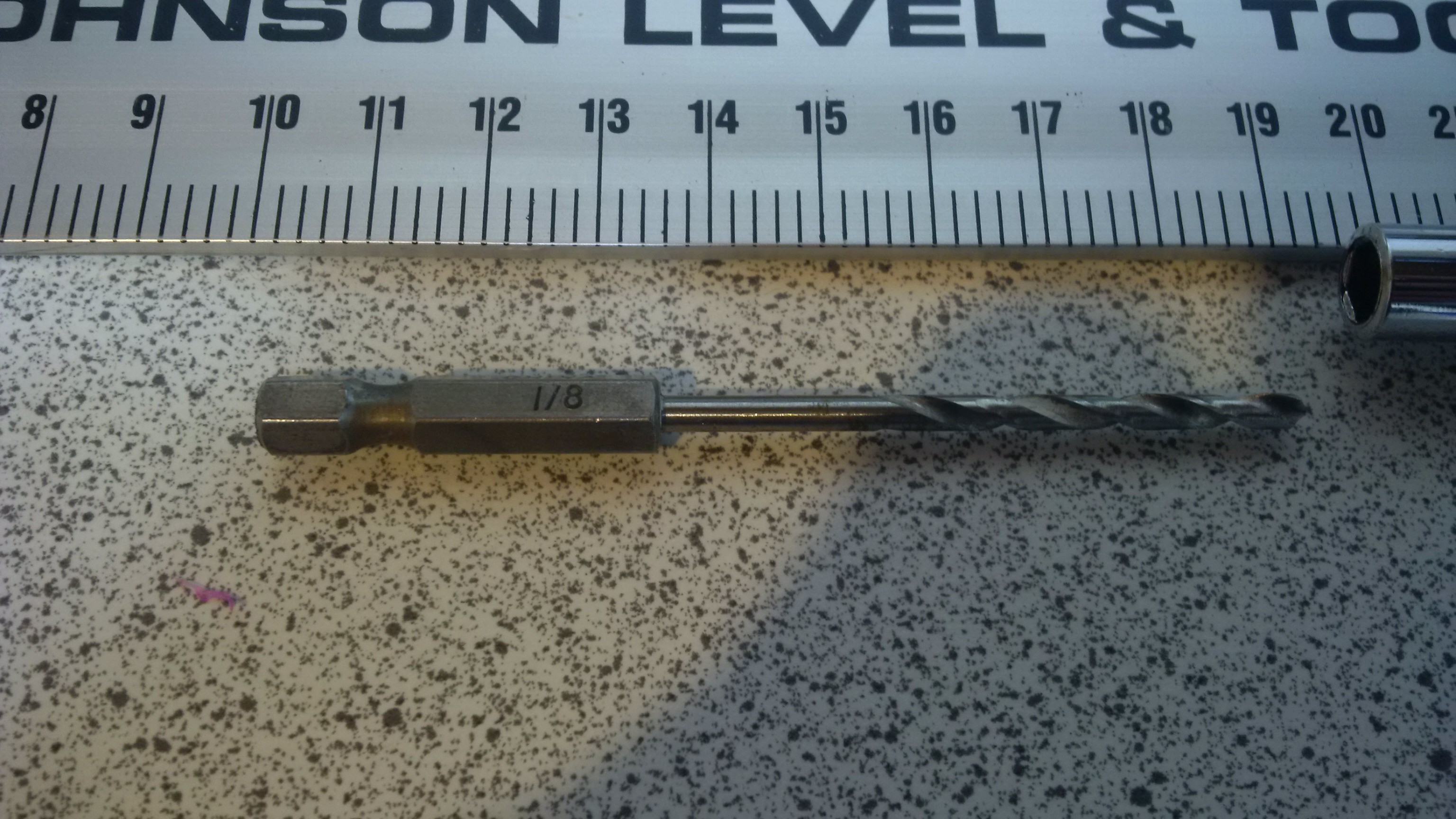 Stick it in a screwdriver handle for hex bits, and you have a grunging tool to get in and do some dentistry.
 Then just push in to each hole and clear out the naughty plastic. Some will already be clear, some will be easy, some will have a personal vendetta against you. Start gently until you get the hang of it, if the bit is sharp, it should be doing the work. You should be able to feel when you bottom out, and try not to drill through the end of the hole and into the main body. Its not the end of the world, but try to avoid it!
Each pin hole is deeper than the pin needs to allow some detritus to be left, test fit a pin and make sure it goes at least half a length in. You can then pull them back out with pliers if necessary. In final assembly you will likely glue them in place.

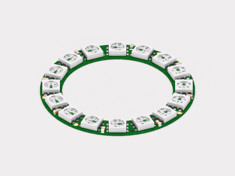
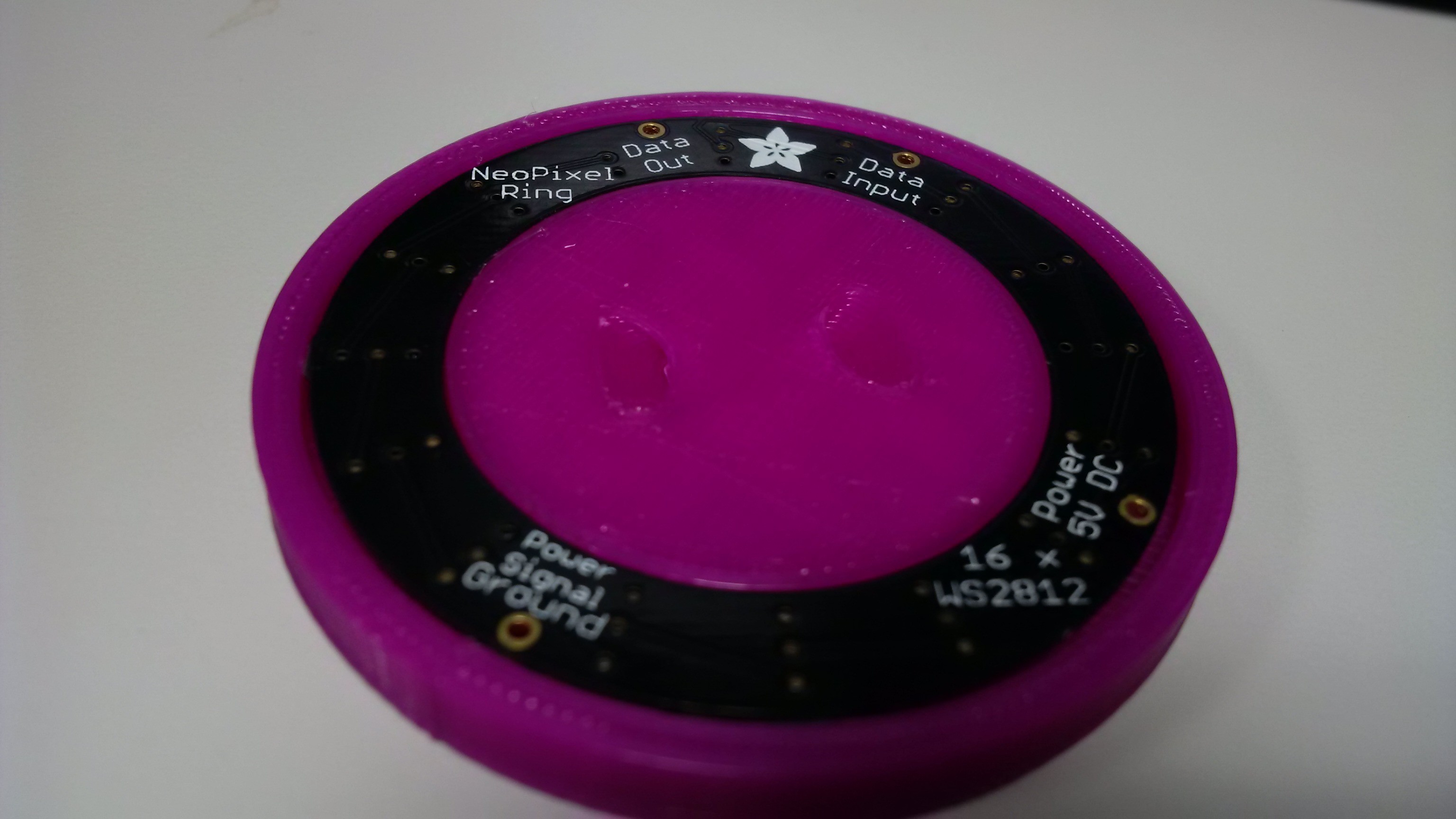
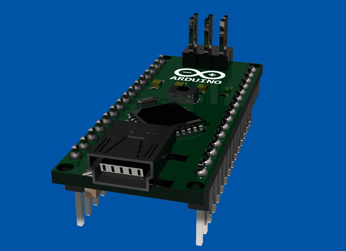
First dimensionally accurate model a 16 led Neopixel ring from adafruit
http://www.adafruit.com/products/1463
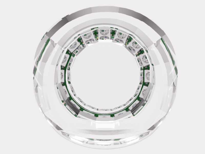
https://fusion360.autodesk.com/projects/neopixel-r...
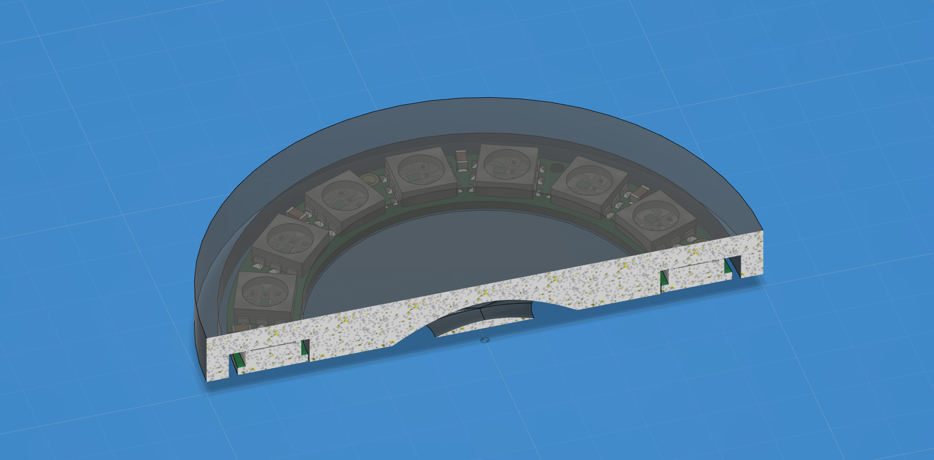
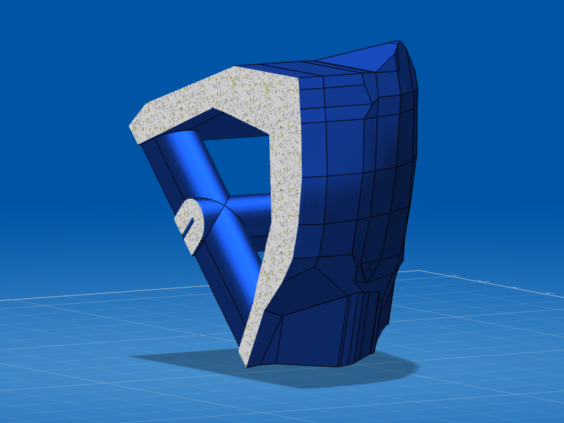
 Then define a body space gap with the model so you can use it as a boolean operator against the piece you wish to mount it in.
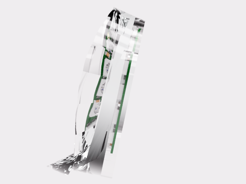
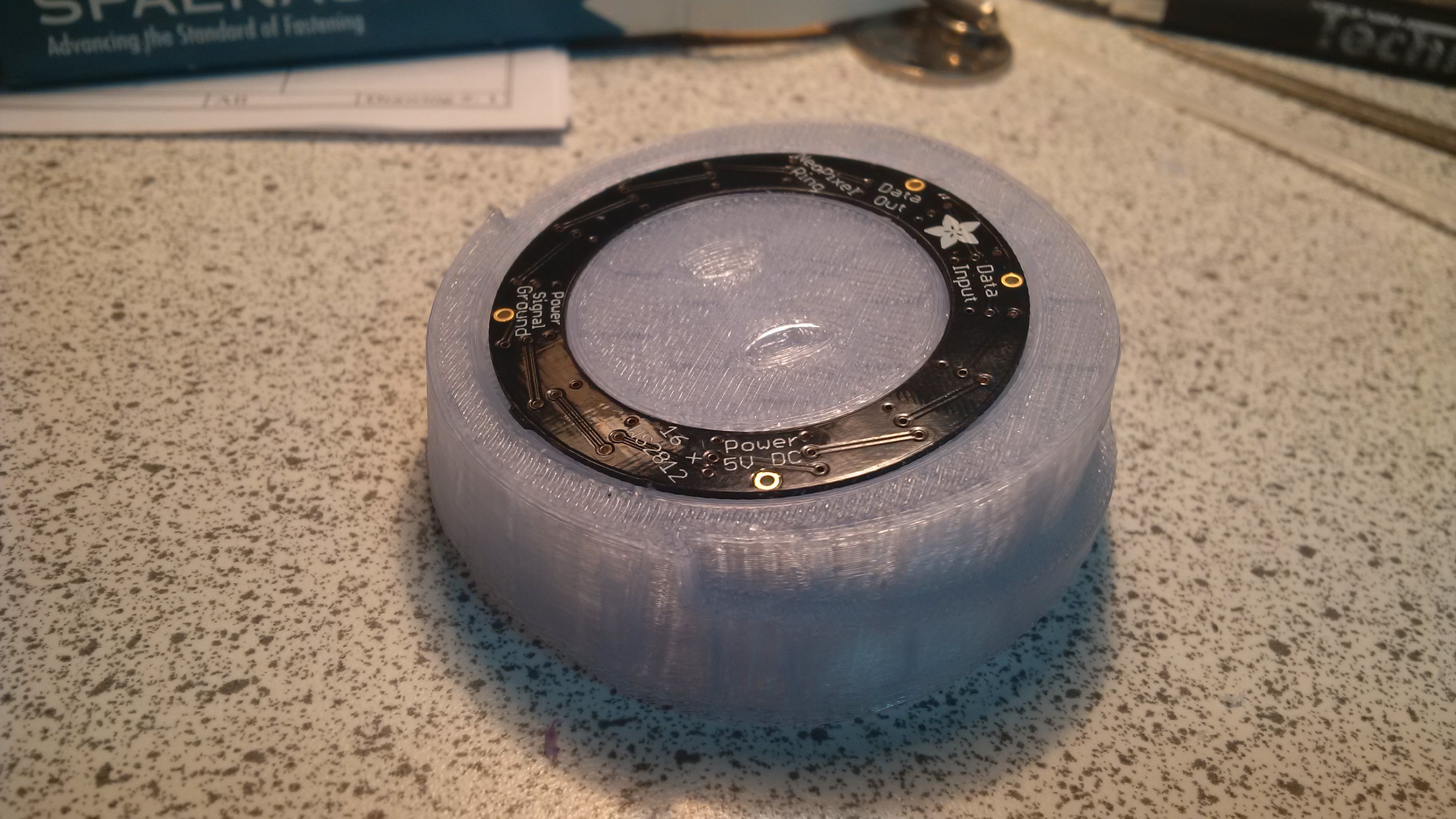
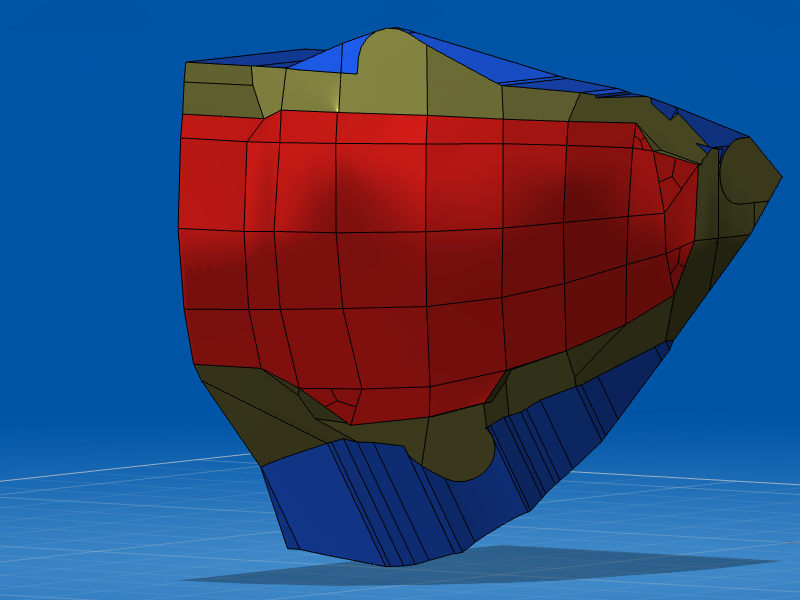
Design a test piece to test the body space fit.
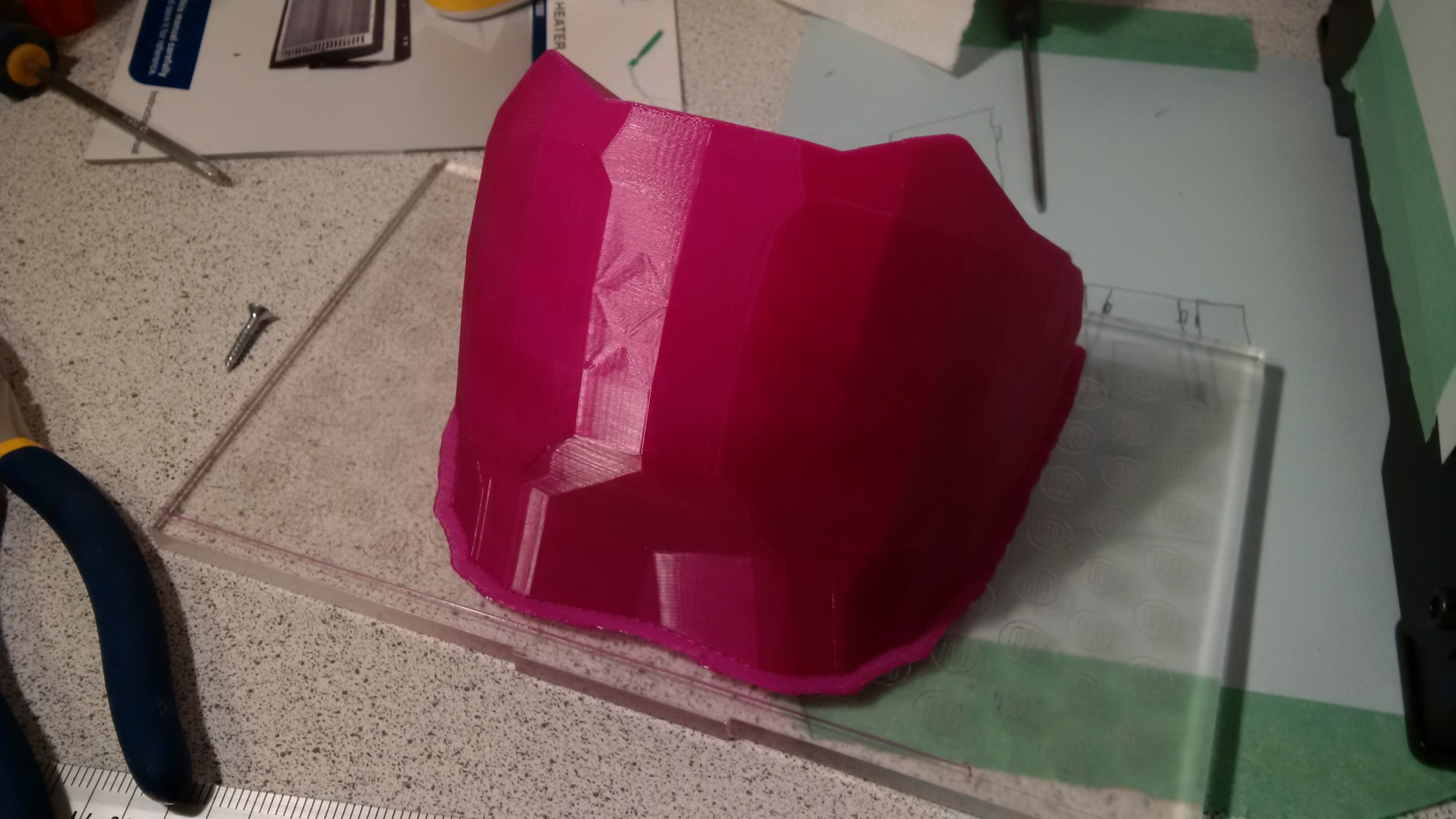
Print it, low material use compared to final part, so you can afford to iterate...Be amazed when it fits like a glove the first time.
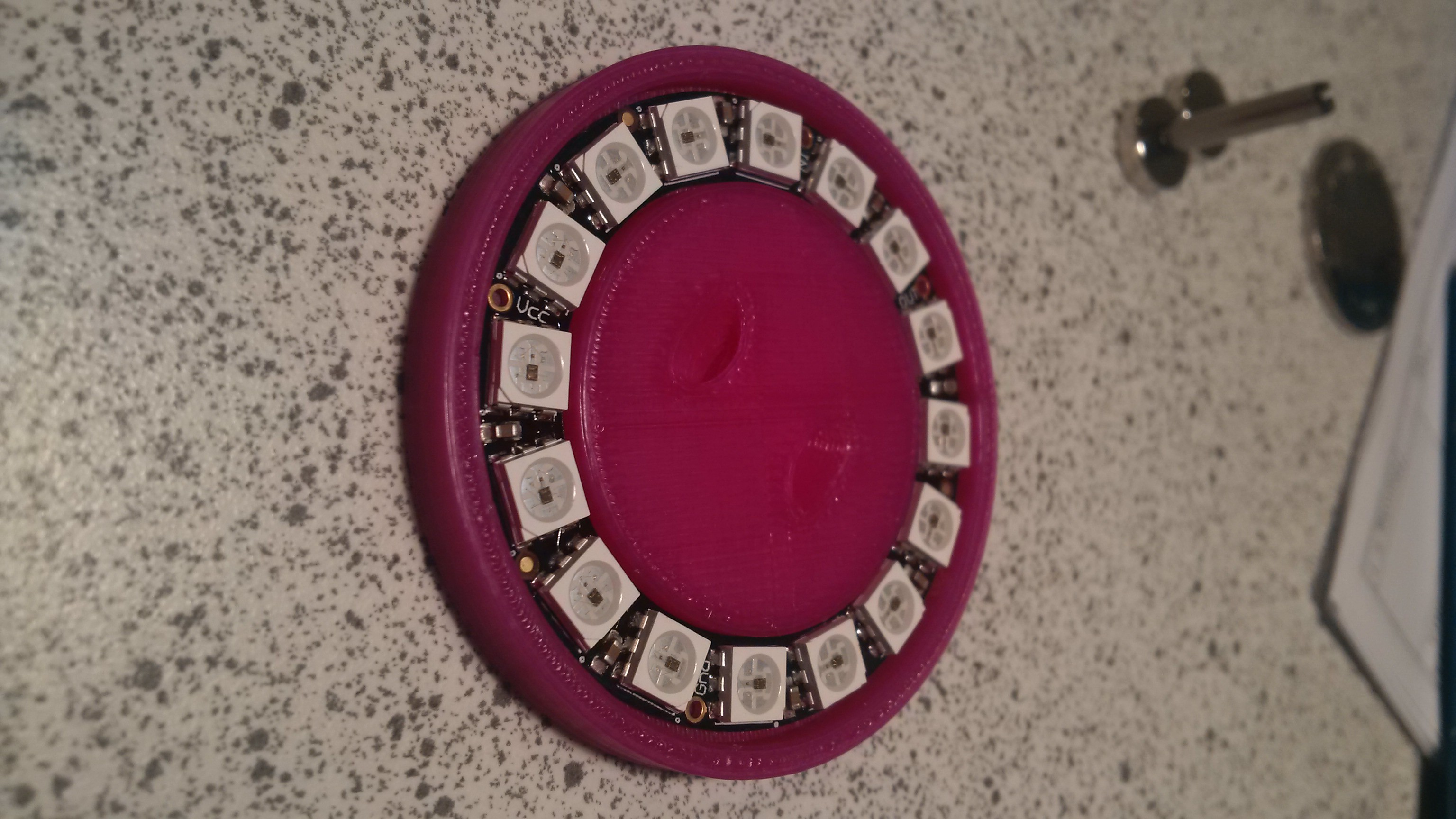
Model it directly into the target part...
Prototype your electronics.
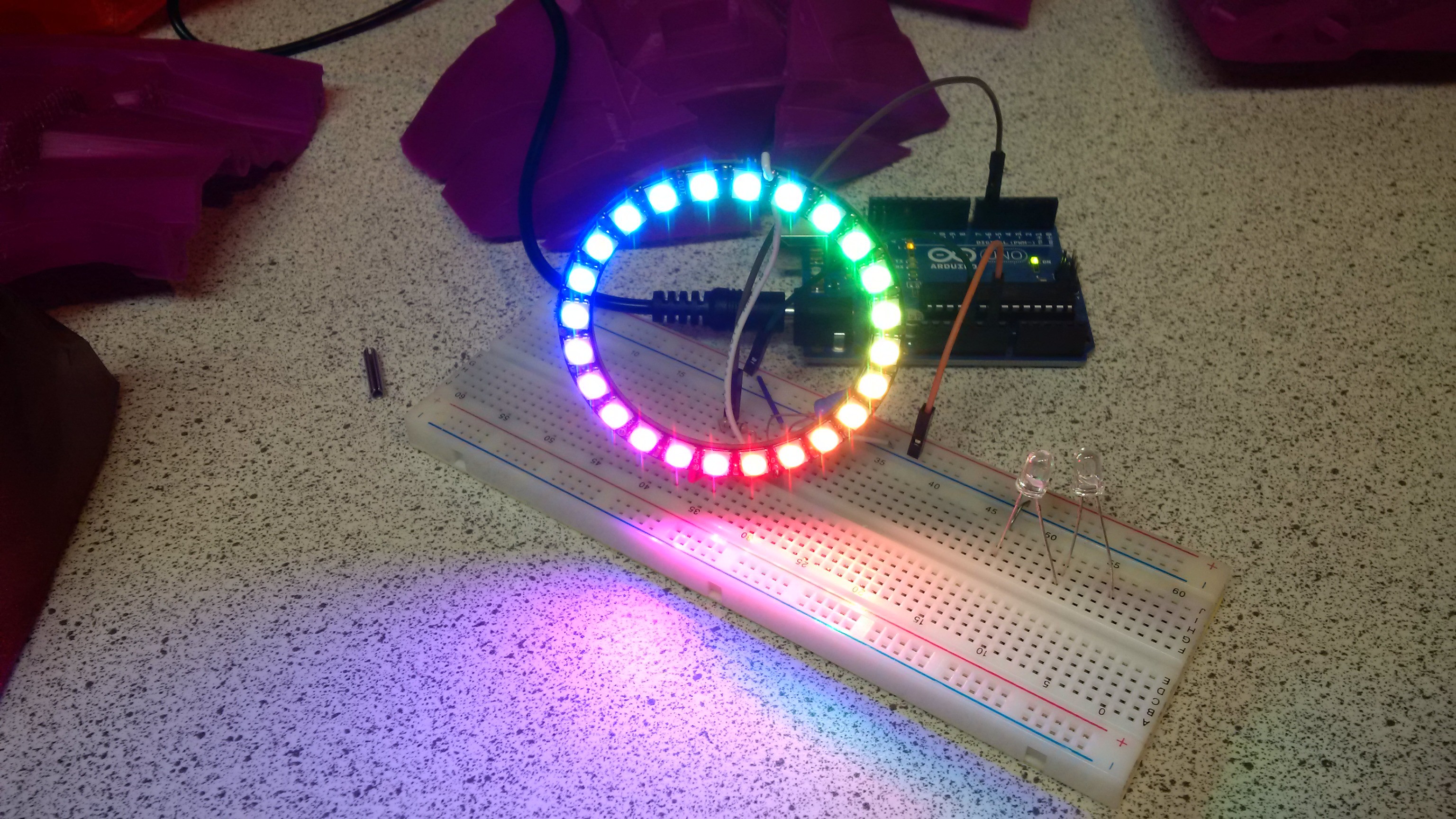
No easier to video when in the helmet, trust me, it looks fab...
to be continued.
Original STL files are hosted in thingiverse at
http://www.thingiverse.com/thing:217267
Work out where your cut lines are
 By looking where it intersects the main model.
Once you have the model, print it.
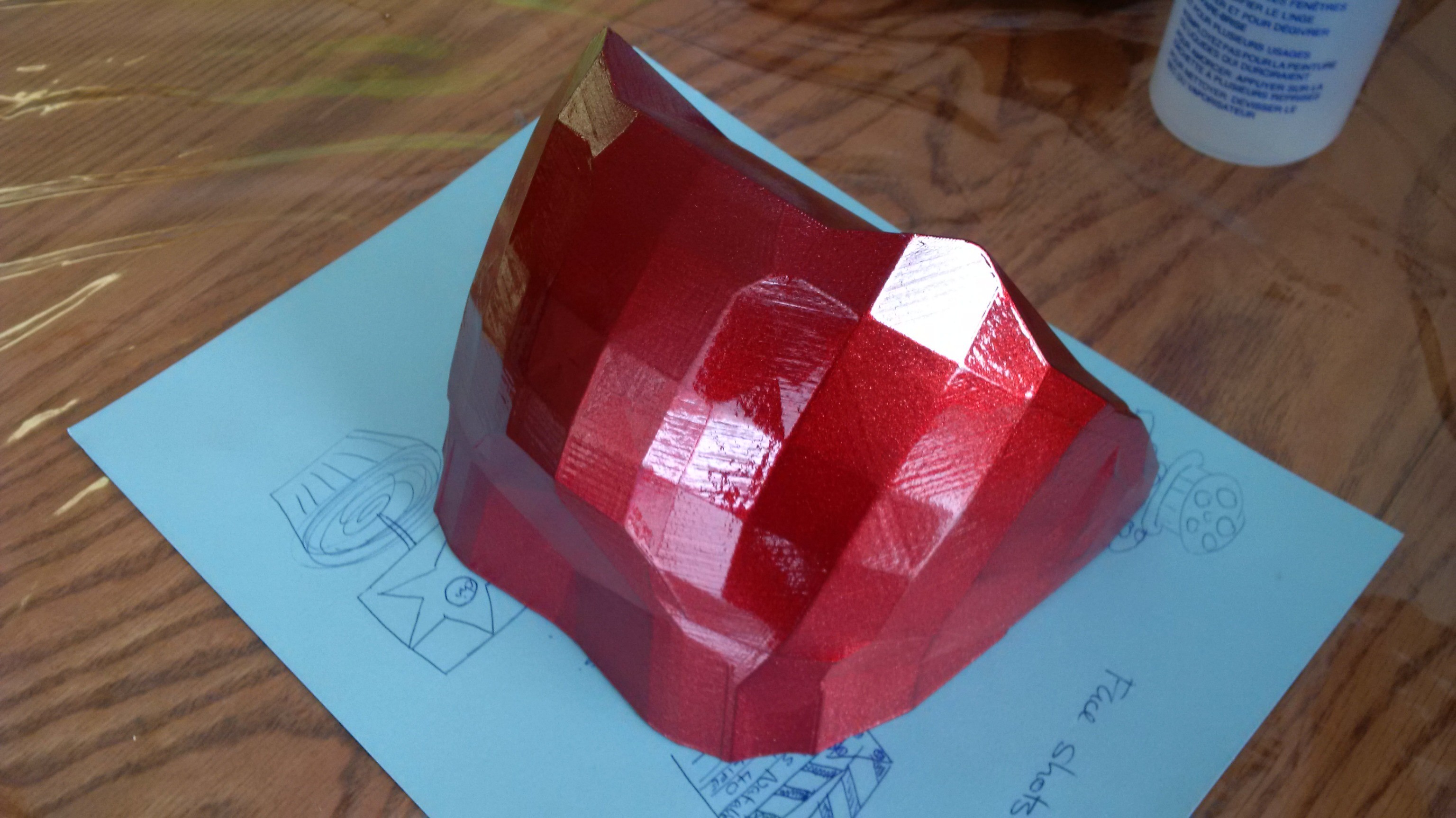
Spray it.
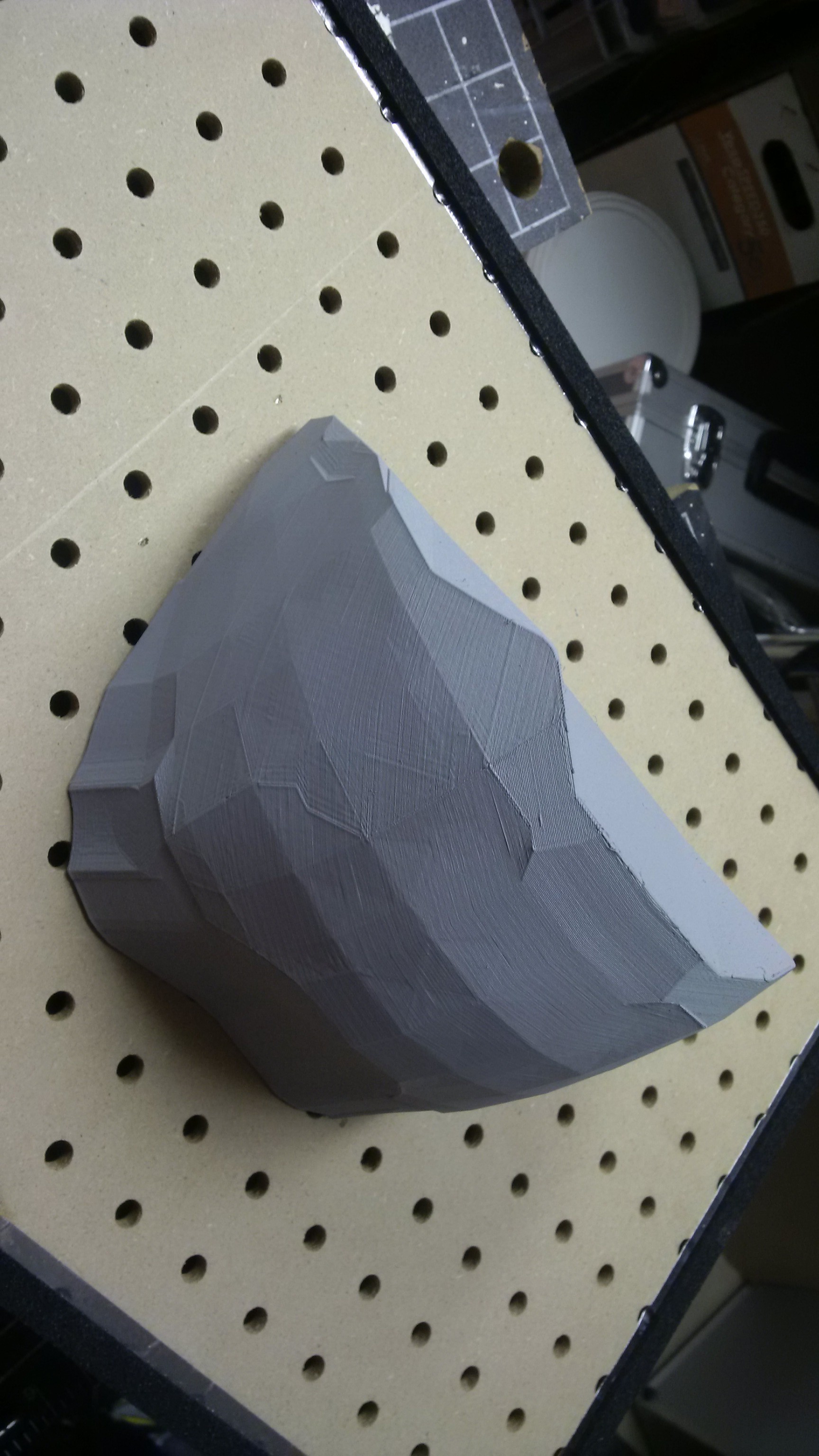 spray it some more
Have pull handles and screw locators for the peg board
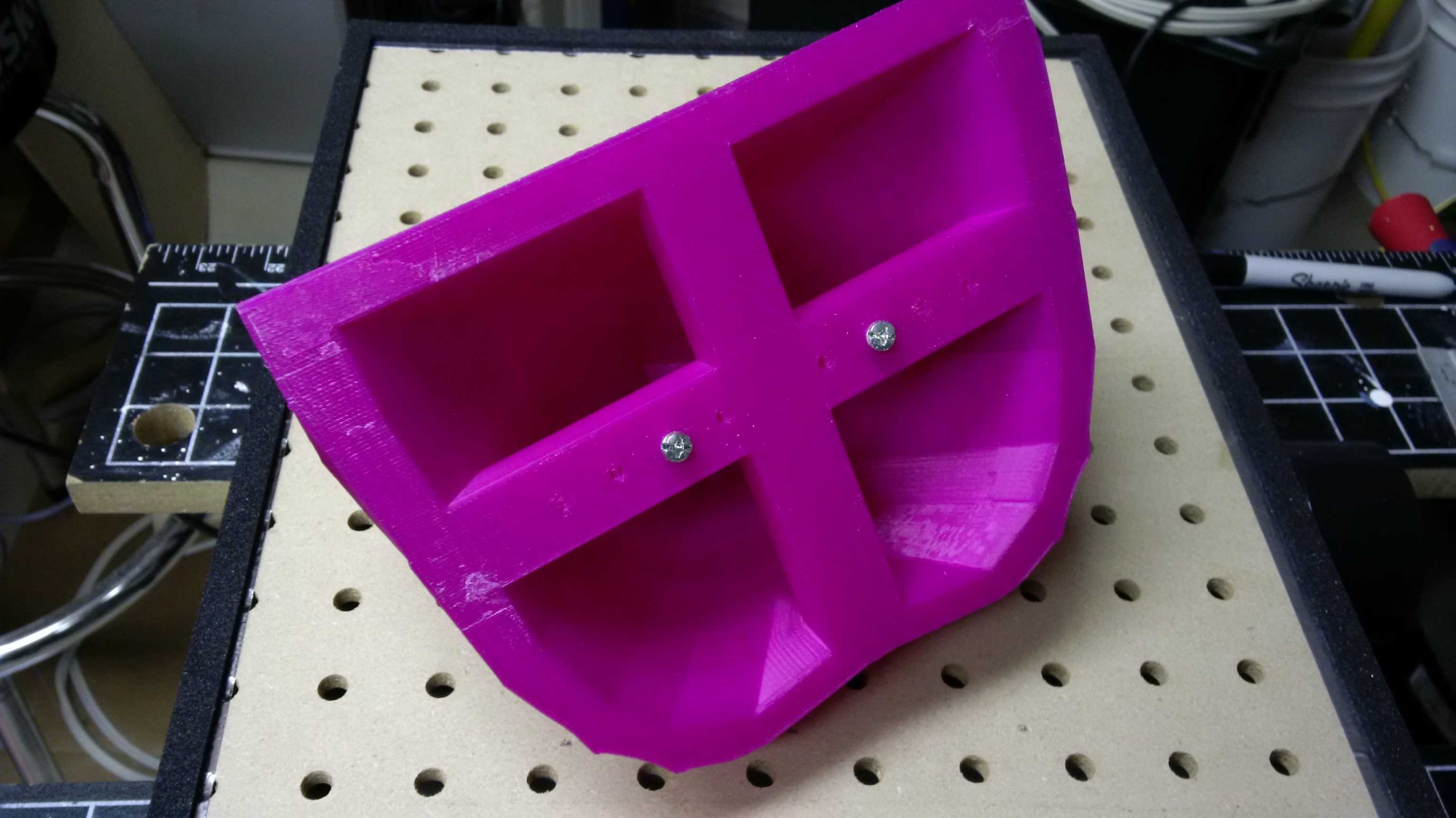
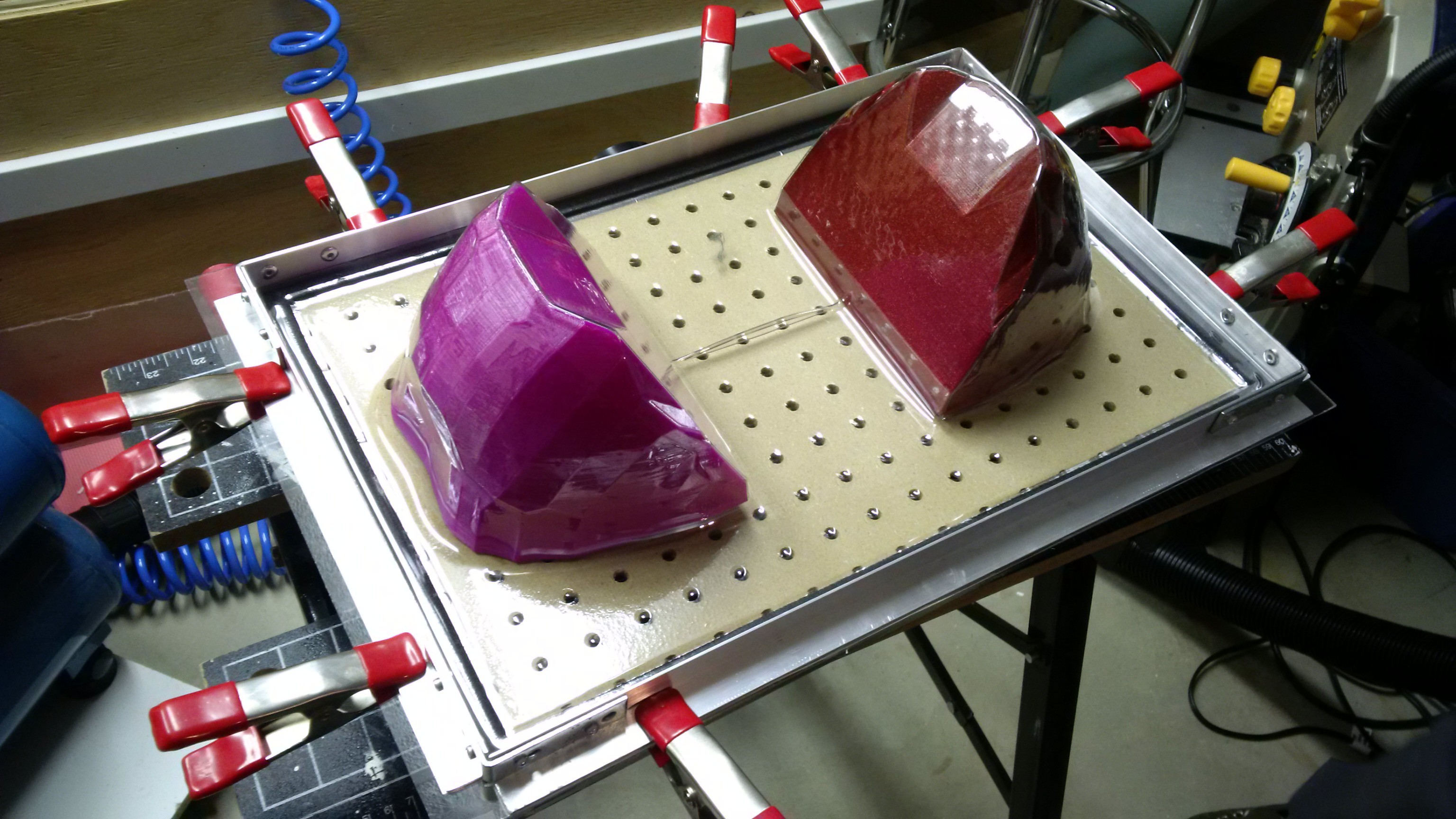
Then pull in pairs out of PETG so the webbing is on sacrificial areas, having first sprayed some furniture polish for easy release.
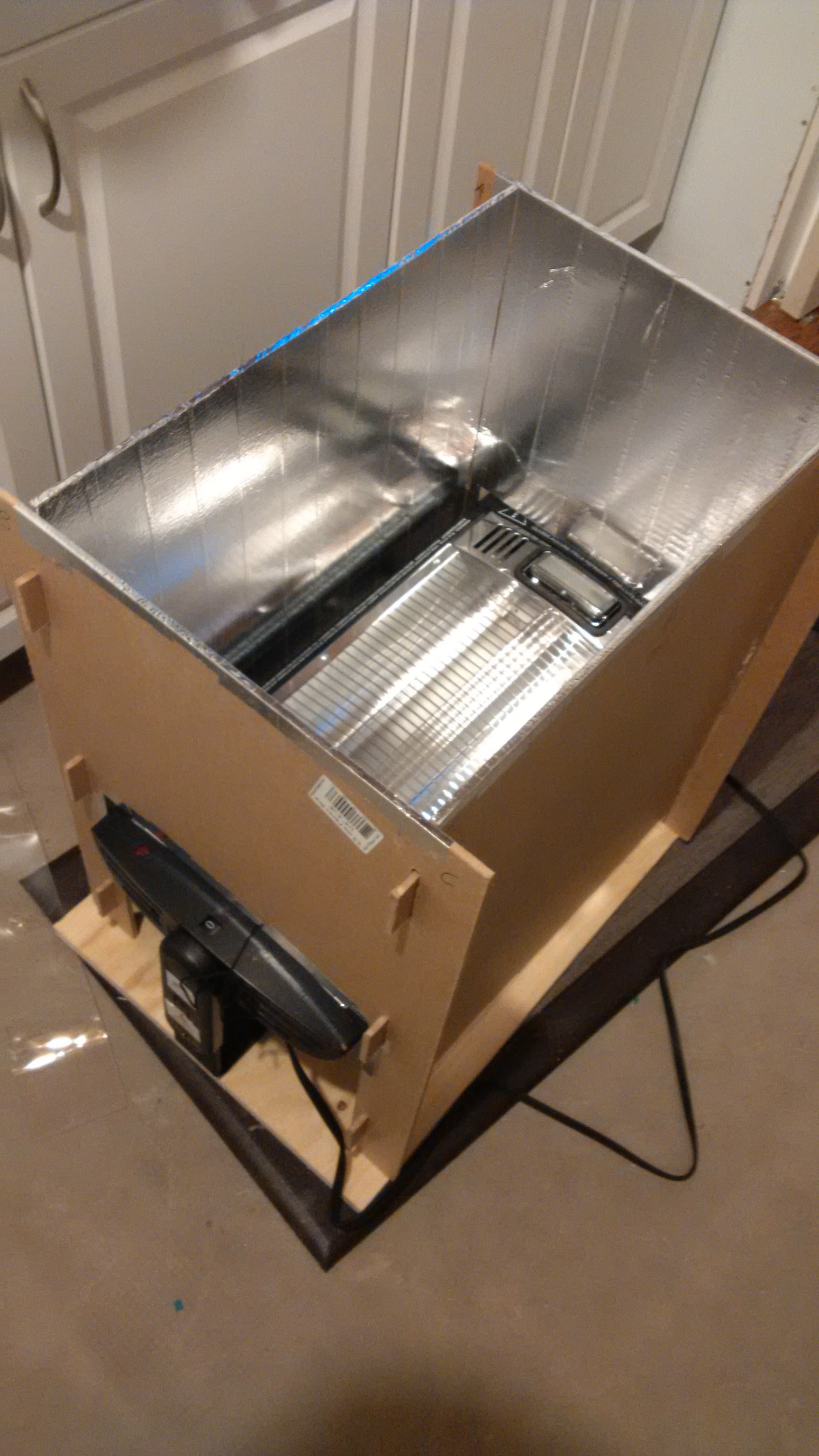
 But first of course heat it on a quartz heater hot box that you can collapse for storage and transport
 remove the molds with a bit of compressed air down the side
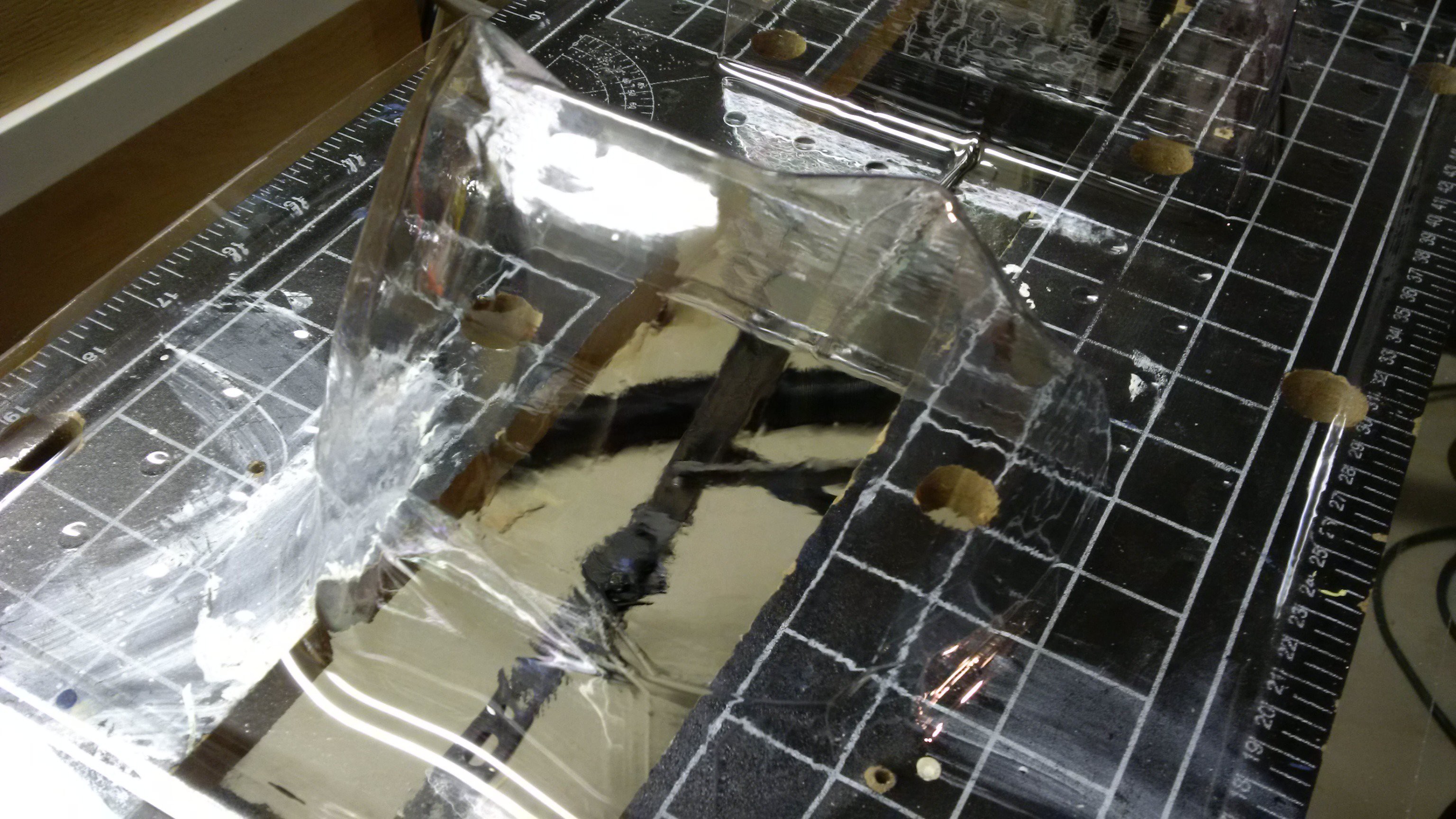 Cut out with metal shears, its just safer, easier and more accurate than a band saw. Add magnets and drop in place.
 Next step is to paint the visor, but that's another adventure...
Step 1 test - these instructions are to test layout / intent of hackaday projects.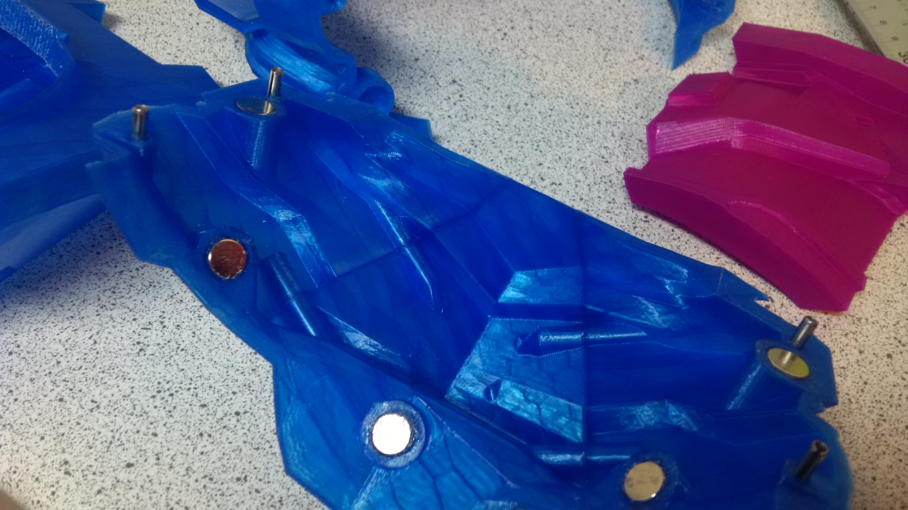
step 2 test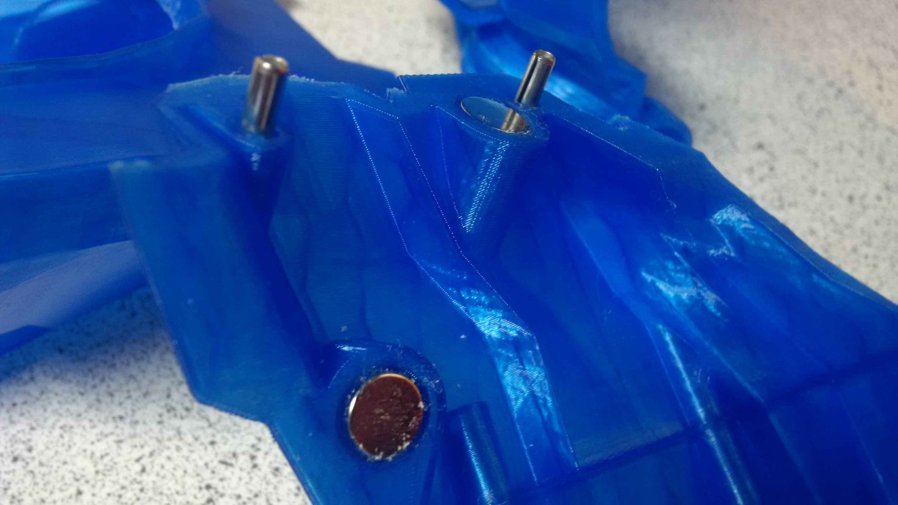
Step 3 test

I just completed my first build of the size A. Such a cool project. I'm wanting to add a more "authentic" visor. Do you know if any off-the-shelf motorcycle or sports visor will work or could be adapted to fit? They're not cheap so I was hoping to see if someone had found a solution to this yet. Thank you!

hey!how many pins and magnets do i need? And where can i order them
Bit of a late reply here, but it might help you still (or help someone else).
For the pins you can use 16-20mm M4 grub screws available from many places online or "hardware stores" that are focused towards mechatronic/tech assembly industries.
If you want a really cheap option and don't mind epoxying everything in place and having to be a bit more careful with alligment, you can just cut up a piece of M3 threaded bar and use that, though it's too loose to just press fit. Don't use 5 minute epoxy as you'll probably struggle to get it all applied before running out of time.
how many of the pins do you need and where did you order them

what size is the adult helmet. My head is 11 inches / 279.4mm in the length and I didn't see anything saying what size it was please help.
Dunno if I missed it, but how much filament does it use (size A)
Is it possible to buy a couple vac formed visors from you? I was going to print the mold and mac a vac form bed, but it was a 30 hour print... or if there is a standard one out there that fits, can you send a link? Maybe some sort of paintball visor would fit
Thanks
Does the visor go in after everything is put together? Or will it need to be put in before the 2 halves go together?

Is it possible to make one large enough to assemble over a basic motorcycle helmet
Anything is possible. However, it would be very big if you were trying to print for clearance.
Practically you would be better off boolean'ing out the motorcycle helmet and printing the parts to stick on.
Quite a lot of work unless you had a very good model of the donor helmet.


 Sina Roughani
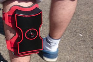
 TAIBHSE DESIGNS
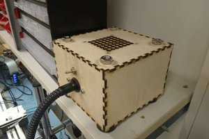
 Øystein
 zapwizard
Any chance of getting the .step or .f3d files for this project? I'd like to get one printed in SLM Aluminium but the wall thickness and thickness caused by the inner structures are a (cost) issue, as SLM/SLS prints have to be 100% infill, and .stls are so tricky to modify with any real precision.
Only way to do SLM/SLS infill is to supply to the printing service with a design including 3D modelled infill stucture that is specially designed to let the unused powder to escape after printing. Even then that can cause quality/consitency issues and not reduce price much, as the powder between the walls generally ends up in a state where it cannot be re-used for the next print.