ziggurat29
-
Serial Killer; The Sorrow of Sad Sorry Serial Stuff
07/07/2017 at 15:46 • 0 commentsSummary:
I implemented UART functionality. The STM HAL libraries an 'middleware' left a lot to be desired. But the cracks therein have been spackled-over, so things look sane from the outside.
Next is to implement USB CDC.
Deets:
Implemented circular buffer. For this first implementation I chose to make this implementation a macro that expands to a full definition of the data and API, with name, data type, and size as parameters. This gives me an STL-esque capability that I can use in C.
The first implementation simply declared the data at file scope, but I noticed that the linker strewed the 'members' about, which was not to my debugging taste, so I made a trivially different second version that kept the members in a struct. To my surprise, this struct version saved several bytes in code space. Hmm! Maybe because the compiler could use a single register to point to the struct and encode the small offsets in instructions, rather than doing loads of the full addresses of the strewn-about members. I didn't look at the generated assembly for this one, so I am just guessing.
I may do some other implementations later, anyway. One idea being to be a little more OO in the implementation so that I won't get the redundant code instantiation since most of the implementation of the methods are identical, only differing in the size of the stored type, and the size of the buffer itself. But that's optimizations for later. Now I need to use this for my serial port code -- both conventional UART (for the printer) and for the USB CDC (for whatever, certainly a logging console initially; I'm a little beyond my one debug LED).
My intention is to use the ST-provided peripheral libraries -- why do I want to hand write all that register-level code? Thats when things got... less than nice.
UART serial implementation in STM32CubeMX HAL
The API look OK; transmit and receive, a spin-wait version (no), and interrupt-based version (OK), and a DMA-based version(OK), and callbacks for TX empty and RX done and error. All this is just OK, but there are some aspects that are not-so-great.
One is that the buffers provided are long-lived linearly addressable buffers. This is not the end of the world, but it requires a little care with my circular buffers in case a run for transmit or receive wraps around. That's my burden to code. The other problem, though, is that when I am notified that either a TX or RX is complete, I don't know what was the originally requested transfer size, so I cannot know how far to advance the dequeue pointer. So as it is now, I do one-byte only transfers so I can know fer shur how far to advance. For RX I needed to do this anyway because I want to set a Data Available (DAV) event for a consumer process to pick it up the moment data does come in, but it is unfortunate for TX that I have to do it byte-by-byte. But whatever.
The second wart in the implementation is the notion of 'state' in the peripherals' Device Control Block (they call it a 'handle', but it is really a big struct you pass around by pointer. The pointer should be called the 'handle'). The state has various enumerated values and it looks like it was conceptually meant to be a bitfield, but the author couldn't quite figure it out. So you need to understand that carefully if you want to be able to full duplex and event driven. Side note, they did alter that implementation to split it into two state variables in later versions of the library, but not the one that is current for this chip. That implementation has it's own quirks, though. While on that side note, here is a caveat: ST does change their libraries' APIs in a non-backwards compatible way from time to time without warning. So, caveat upgrader!
Anyway, I worked around these warts and made an API that looks a bit like a non-blocking stream that you can push data into and pull data from at will whenever, and also has a DAV event that you can have a consumer thread block on until stuff comes in to process. I initially implemented that with a binary semaphore, but then I learned about 'task notifications', which are much more efficient in this case, so I migrated to that. (Oh, did I mention I'm using FreeRTOS for this? I am.)
My initial test was to squirt out a fixed text string to the serial port which I then attached to the ever-popular and thoroughly-indispensable FTDI adapter and then to my computer, to view with PuTTY. (Tip: I try to always have about 5 or so FTDI boards on-hand at any time. They're just too handy. Tip on Tip: ALWAYS use FTDI and NEVER use Prolific. Just sayin'.) I had a bug initially by not locking around the circular buffer operations. I knew better than this and already had comments in where I wanted the locking calls to go, but I thought I might get away with it. Wrong! Most of the time it worked fine, but once in a blue moon a character was dropped, and then subsequently a stray character was in the stream. Well, that's what I get! I put in locks around the enqueue and dequeue buffer operations and now the serial code is seems quite solid.
So, all that worked out, and I tested by forwarding the decoded IR data to the serial port, and it looked as expected. No more manually decoding on the scope trace!
I also hooked the callbacks that are invoked on IR parity error, and lost/bad signal, and use them to light the one LED on the board. A separate task turns the LED back off after a few seconds. This will allow me to do some simple range tests with ease.
The resulting API is:
//transmit data via UART2; returns bytes enqueued
size_t UART2_transmit ( const void* pv, size_t nLen );

//read data received from UART; returns bytes dequeued
size_t UART2_receive ( void* pv, const size_t nLen );

//maximum that can be read from the UART2
size_t UART2_receiveAvailable ( void );

//maximum that can be pushed into the UART2
size_t UART2_transmitFree ( void );

//optional callbacks you can implement to get notified of xmit/recv
void UART2_DataAvailable ( void );
void UART2_TransmitEmpty ( void );
Next:
Next, I want to get the virtual serial port over USB working. I want this at a minimum for debugging logging output, but eventually I will put more fancy functionality in there. It has occurred to me that this receiving interface might be useful to some folks in it's own right, even without the printer attached.
-
Tool Everything Tool Terrible Two: OpenOCD Rift
07/05/2017 at 17:44 • 0 commentsSummary:
- System Workbench woes have befallen me
- Error messages are horrible
- I have worked around it again, and want to record these things for posterity
Did I ever mention how much I dislike Eclipse in particular and Java in general? Well, I guess I just did.
Deets:
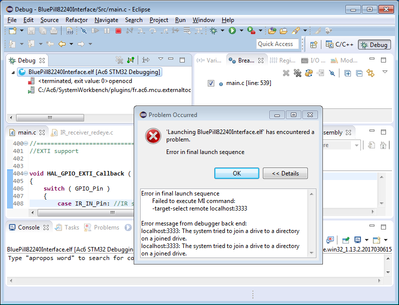
OK, today, spontaneously, my debugger fails to run. I now get the dreaded "Error in final launch sequence" message. 'Details' reveals "The system tried to join a drive to a directory on a joined drive."
![]()
"Joining drives", WTF? This error is a Windows error, 138 (0x8A) ERROR_JOIN_TO_JOIN, and the message comes from using FormatMessage to translate a GetLastError() result into some friendly text. Veteran Windows programmers will already know that you have to take these things with a grain of salt, because you are hoping that the programmer did a SetLastError() with a sane and meaningful value -- there's nothing that enforces that sanity. Also, sometimes between where an error occurs, and where you get around to doing a GetLastError(), there is enough intervening code that the error value no longer reflects that generated by the root cause. Anyway, I thought I'd give a brief mention about this particular error code in this particular instance.
First, what does it mean? The literal text refers to an ancient facility from DOS whereby you can 'JOIN' a drive onto a directory of another drive's filesystem. It's a little like mount'ing in *nix. I have never seen anyone use this facility in over 30 years. Presumably it was to extend storage by, say, JOIN'ing a whole 'nuther floppy onto a directory that some application used for data storage. Whatever it was for, the facility (along with SUBST) still exists to this day in the NT-derivatives (though implemented differently). Microsoft does like their backwards compatibility.
So why are we getting it here? Well, that is Java's fault. An error occurs within Java's Windows platform-specific implementation, and that implementation chooses to simply do a GetLastError() FormatMessage() and bubble the results up. A much better implementation of Java would have been for it to have said something about what Java was attempting to do when the error occurred, because I can tell you it certainly wasn't trying 'to JOIN a drive to a directory on a joined drive'! Years ago, I did debug into Java to find where it originated for an unrelated reason, but I can't recall exactly where, alas, so you'll have to take my word on that. Or not; your choice.
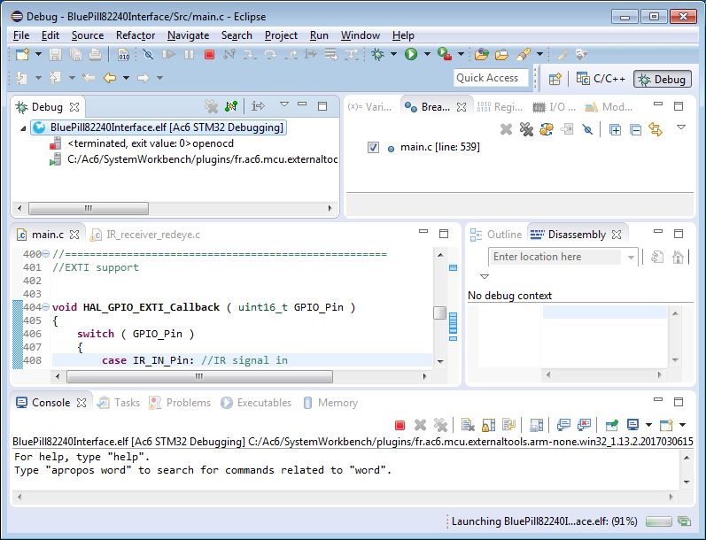
Anyway, as a result of all this, googling on that message typically will not give you useful results because this comes up in many unrelated products, and arises from many unrelated causes. I can tell you that in this case, what is happening is that the openocd.exe process is terminating unexpectedly, causing the pipe to be broken, and other stuff (gdb) to lose connection to the localhost port on which it is listening (3333 in this case). You can see it here:
![]()
In the 'Debug' tab, you can see "<terminated, exit value: 0> openocd" with the red stop icon, and the GDB process is still running below it. Exit value 0. Hmm, that usually means 'normal termination'. Who knows, though, that's up to the programmer to be meaningful as well, and a lot of folks don't set the process return value to distinctive things. But it definitely terminated for one reason or another, and that certainly would bring debugging to an end, since openocd is what interfaces with the ST-Link v2.1 pod.
So, what to do. Well, you'll have to dig into Eclipse for that, or more properly, the AC6 plugin to Eclipse that is what is doing all this launching stuff. Not thanks. Here is my work-around; it's a little klunky, but at least it does work.
Work Around for Can't Launch OpenOCD Joined Drive Nonsense
What we will do is create an 'external tool', and manually launch that, and just leave it running. This will be our manually launched OpenOCD instance. It's a little klunky, because the joys of our IDE automatically launching stuff will be over, and also because as it turns out, the configuration will be project specific, so you'll need to twiddle with it if you work on multiple projects at once. More details about that later. First, creating the external tool.
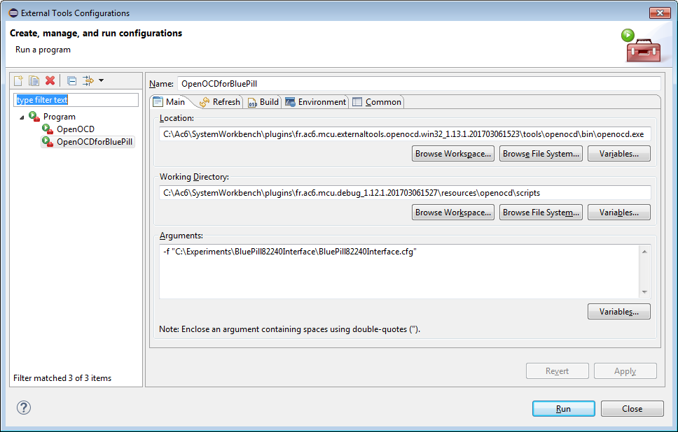
Under Run, External Tools, External Tools Configurations... create a 'New launch configuration'. There is an icon in the upper left, it looks like a page with a "+" sign on it. Do that, and give it some helpfull name like "ICantBelieveIActuallyHaveToRunThis". For reasons of space in this example I used the more pedestrian "OpenOCDforBluePill". Tip: do not use spaces in the name, or you will never be able to access it, or ever be able to delete it. So be careful with that axe, Eugene.
On the 'main' tab, you will need to specify the 'Location' of the openocd.exe, the 'Working Directory' where that process is launched, so it can find it's data, and the 'Arguments' that are passed on the command line for the process. Here is what mine looks like:
![]()
I have only ever gotten this to work with absolute paths, not of the fancy 'Variables...' seem to have any effect. Consequently, this External Tool is bound to the version of System Workbench I have currently installed (via 'Location' and 'Working Directory') and also this particular project (by 'Arguments'). Sigh. But, I do now have a working environment, so there's a good thing!
OK, how to use:
Before you start debugging, you will need to run the External Tool from the Run, External Tools flyout menu. This will stimulate a build first just because, then you will see OpenOCD process running, with the green icon.
Then, when you are ready to debug, just the 'bug' button as per usual. This will attempt to launch a separate openocd.exe, which will die, but the gdb will connect instead to your manually started one, and you will be off to the races once again. Note: you might or might not get a new message box complaining about the second openocd having croaked. Just dismiss it. It can't run successfully because the localhost port 3333 is already being used by the other successfully running process.
An upshot is that you will be able to see the openocd console output, so you can see more info about why it's croaking, if it does still croak on you.
OK, now back to work on serial port stuff....
Next:
Now I am working once again, so I can proceed. Again.
-
Giving the Blue Pill the 'Red Pill'
07/05/2017 at 16:04 • 0 commentsSummary:
* My Blue Pill dev board(s) arrived; now I have 6
* The board had some software protection kookiness that had to be worked around (hence 'Red Pill' reference)
* I got the board working with the toolchain
Now it's time to add some higher-level system functionality; probably UART (and maybe USB serial for debugging), circular buffers, and event notification.
Deets:
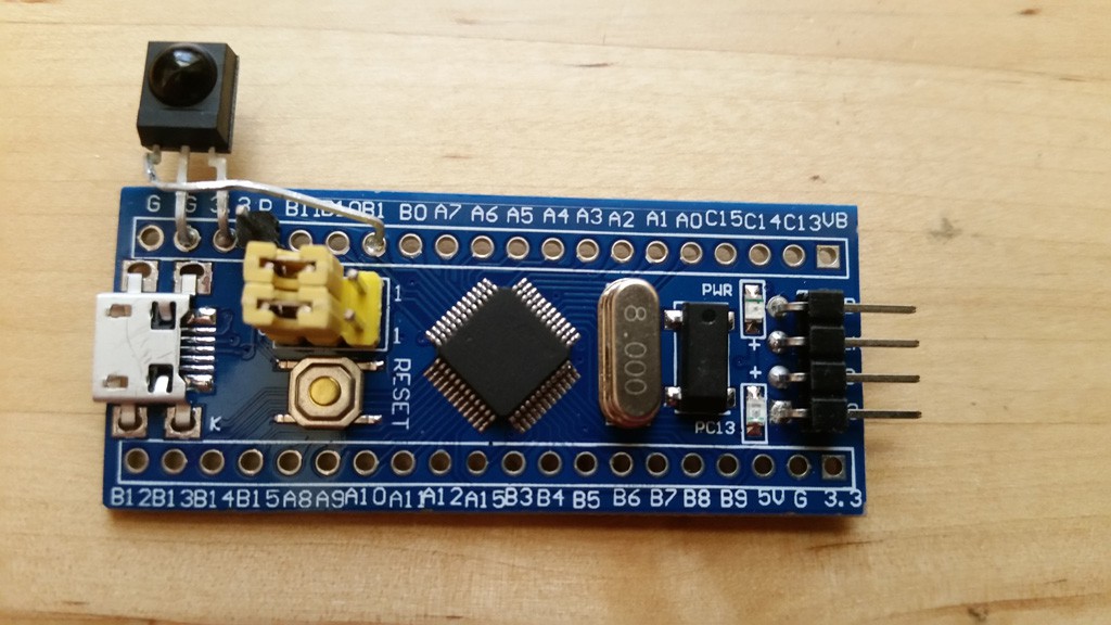
Today, my 'Blue Pill' 'STM32 Minimum System Development Board' came in. Interestingly, both the 5-pack I ordered domestically, and the 1-unit I order from China. I guess it came on the fast boat from China this time. So now I have plenty to destroy in the process of this project.
The board uses a STM32F103C8T6, and it was straightforward to set up a STM32CubeMX project with that processor. I went ahead and declared assignments for the very few hardware items on the board: A jumper for BOOT1, a push button, an LED, the USB, and the two crystals (I'm a little surprised they splurged for to crystals).
Now I have to decide where I'm going to put my hardware. Looking at the pragmatics of physical placement, I have decided to put the demodulator on PB1 because I should be able to bend the pins on the Vishay TSOP-4133 and connect it there next to where power is also available. I've pretty much decided to put the printer on UART2 using PA0,1,2,3. I believe the printer uses hardware flow control, so I wanted the RTX/CTS lines, and UART1 has those tied up with USB. Anyway, UART1 is used for the bootloader, so I just as soon leave that free for now.
Next I wanted to do an initial test drive of the toolchain. Immediately upon connecting the board (via USB, which also supplies power), I noticed /something/ enumerating on the system. Hmm. That means the chip is not blank. The thing enumerates as "Maple 003" vid/pid 1eaf/0003. I don't know what this is, the vid/pid don't lookup to anything known, but I am guessing that it is a bootloader that is meaningful for the Arduino guys. Interestingly, the board from China does not have this, it just has a 'blinky' application running. Another minor difference is that the board from China has an amber led, whereas the ones shipped domestically have a red led.
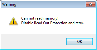
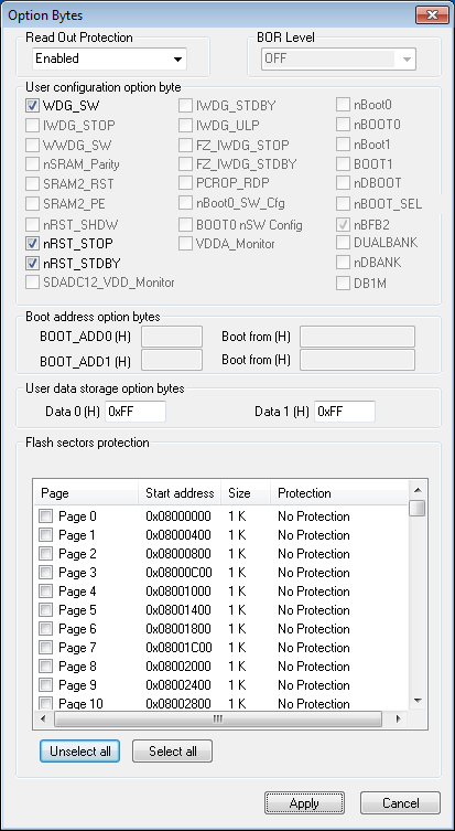
There was a little challenge, though, in that I could not program the device initially. I started up "ST-Link Utility", and it complained about "data readout protection".
![]()
I see how the game is played! Who knows why they turned on DRP, but fortunately, it turns out that this is reversible. Using the ST-Link Utility, and navigated Target,Option Bytes..., select 'Disable Read Out Protection'.
Option Bytes before:
![]()
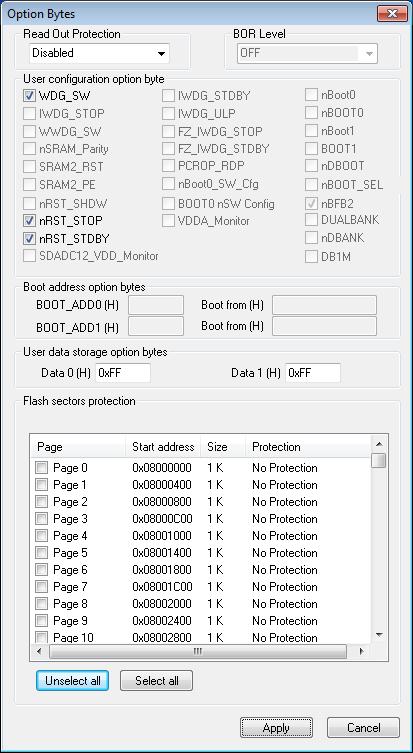
Option Bytes after:
![]()
FYI, the board from China did not have this challenge, so your mileage may vary. Also, apparently you can do the same from gdb/OpenOCD directly with the command:
monitor stm32f1x unlock 0
This resets the protection and erases flash. So he board has taken the 'Red Pill' and gone back into my Matrix, and now I have a blank board.
Tool Time:
I started up the System Workbench, but I could not get the debugger working. The complaint was 'unable to erase flash'. I fiddled with the openocd configuration file, but to no avail. In the end I hazarded a guess that the NRST line needed to be connected, since that was notably missing from the 4-pin connector at the end of the board relative to my other boards (that, along with SWO). NRST is available on the side, though. I soldered a 1-pin header on that, and connected it, and then things were working.
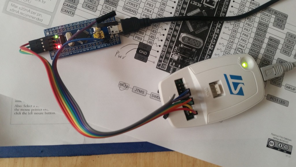
![]()
I still suspect that there might be some clever openocd magikry that can be put in the config file, but I don't know what it is. I'm up now, so I'm not going to look further (at least at this time).
UPDATE: I did figure out how to avoid needing the NRST line. It's a bit convoluted. First, you must have a 'debug' configuration to edit. If you start to debug, it will fail, but in the process you will have one to change. Then select project properties, and "Run/Debug Settings". Select the newly configured debug setting (or just skip to this step if you already have one. Then select 'Edit'. This will open a new dialog, and select the 'Debugger' tab. Down the page, you will see 'Show Bootloader Options' that will expand things further (it will be 'hide' if you've already been here). Once you've expanded that stuff, there will be an item 'reset mode'. The default will be 'connect under reset', bu you will change that to 'Software System Reset'. Tada! What all this means is that a software command is sent over the SWD lines to reset the board at the start of debug, instead of using the hardware reset line.
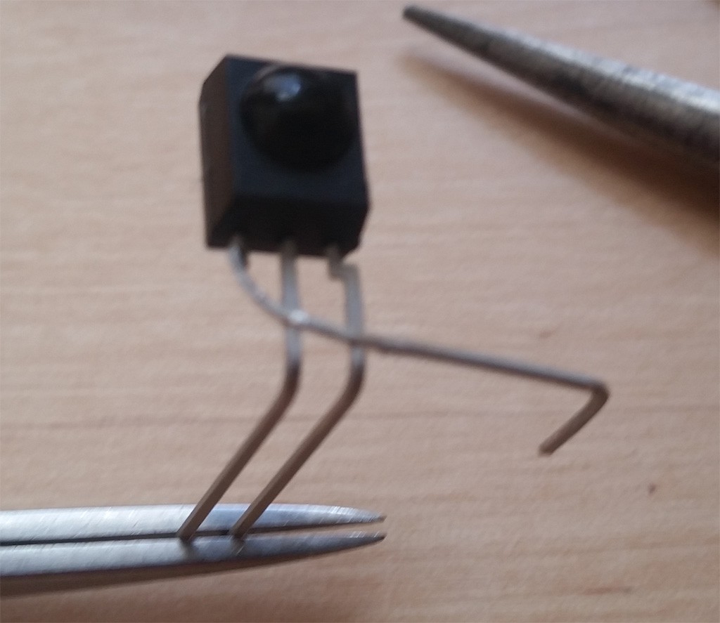
I bent up my detector like this to mount it on the board:
![]()
The added NRST pin is a mild annoyance, since it is right in the middle of where the detector line is being routed, but a little bendage of that wire keeps things reasonable safe from shorts.
![]()
OK, so I'm back up with the new board!
Next:
Now that I am in the same spot as a couple days ago -- just with the new board -- I can continue work. I need to implement a bunch of system code in advance of receiving the printer unit. I will probably start with UART support. I possibly will also implement USB CDC so that I can have a means of getting debug output as well.
-
Decoder Coder
07/02/2017 at 22:25 • 0 commentsSummary:
Coming off of yesterday's apparent success with the low-level signal stuff, I decided to start coding the decoder.
My current idea is to measure the distance from bursts, and that, combined with knowing the last bit received, will allow me to correctly decode the incoming signal into actual data values.
This worked. (And now I have an even better idea.)
Deets:
Yesterday I mentioned that I believe I should be able to decode the bit values by measuring the time between bursts, coupled with knowing what was the previous bit value. I started by making a table of the 4 scenarios, and computing the related timing value in timer ticks.
Here it is:
![]()
Case 0,0 and 1,1 have the same timing value, and so it is necessary to know the previous bit to disambiguate. Actually, this case is pretty easy: the current bit is whatever was the previous bit.
For the code, I implemented this as a sequence of range comparisons. This picks up faulty cases as well as the valid ones. For faulty ones, I am currently going back to the 'hunt' state, but I could conceivably do error correction using the parity bits in some cases. I'll mess with that later, though.
Because of my merged pulse work-around, the first burst may be coming in during the timer ISR (if the first bit is a '1'). I need to take that into account. Further, if the first bit is a '0', then I also need to take that into account in the EXTI ISR. I handle this situation in two ways:
- if there is a burst, then this bit is definitely a '1'. Go ahead and shift it in, and set the 'last edge time' to 0, which is what it would be if we clocked it in from a perfectly demodulated signal.
- if there is no burst, then we know the bit is a '0', but we can't shift that in yet, because later we will have a burst in the second half-bit time, which will be coming in via the EXTI handler. So, we fake the system a little, by pretending we have already received a 0-bit, and setting the 'last edge time' to -28 (where the sample would be if there really was a preceding 0 bit). Doing this makes decoding work out correctly in that case.
The rest of the signal decoding occurs in the EXTI ISR, and bits are shifted in as they come in. To handle timing variances, I am using a 1/4 half-bit time window around the ideal sample time. I implemented the logic as a series of comparisons to categorize the time into the various cases.
The code for this logic works like this:
uint16_t tNow = GetTimerCount();
uint16_t tDelta = tNow - _tLastSample;	//ain't 2's complement great?

if ( tDelta < (28-7) )
    {}	//error, too soon
else if ( tDelta < (28+7) )
    {}	//case of 0,1 or error
else if ( tDelta < (56-7) )
    {}	//error, possible noise
else if ( tDelta < (56+7) )
    {}	//case of 0,0 or 1,1 this bit is the same as what precedes it
else if ( tDelta < (84-7) )
    {}	//error, possible noise
else if ( tDelta < (84+7) )
    {}	//case of 1,0 or error
else
    {}	//missing pulses
OK, testing time! Decoding the signal is a real-time process, so breakpoints are not going to be useful. I reach for my handy debugging GPIO once again. This time I simply set the line to be whatever bit I am shifting in.
Following are a couple traces of the signal from my calculator. As per usual, the CH1 (yellow) trace is the demodulator output, and the CH2 (blue) is my debugging GPIO. When looking at this trace, realize the pulse width of the debugging data signal doesn't mean anything. Rather, it's level is meaningful at the time that the demodulated IR signal goes low. So you can think of the IR signal as a 'clock', sort of. For convenience, I have annotated the trace with the bit values being shifted in.
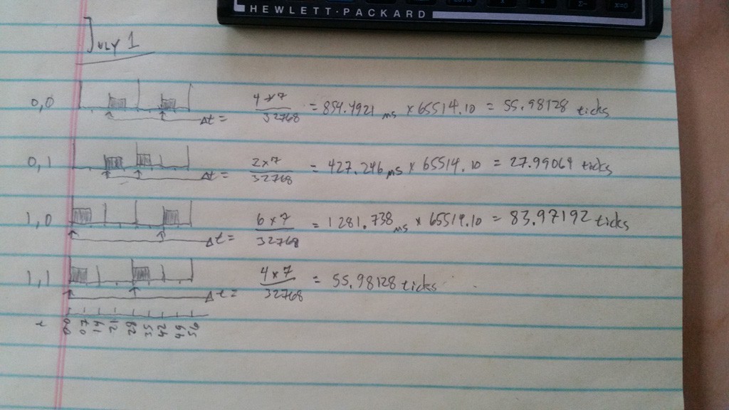
Trace 1:
![]()
This first trace exhibits the 'merged pulse' issue -- you see the first 4 pulses are merged into one big one. The timer trick I described yesterday works around it, and also samples the first burst period, which in this case does happen to be bursting (hence the initial '1'). When the end-of-frame timer expires, I return the GPIO to 0 so it is easy to see when the next transmission comes in. This transmission decodes to:
1011 0101 1011
The first 4 bits are parity, and I won't discuss that in detail here other than to say that the 4 parity bits are individually computed over a distinct subset of the data bits, and are set to create even parity. The next 8 bits are data. So this value is 0x5b, which is the code for the '[' character.
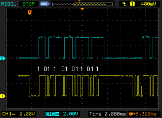
Trace 2:
![]()
In this second transmission, the Vishay device demodulated ideally, and you can see the three start bursts the first data burst distinctly, without merging. But it doesn't matter because the workaround works the same for all those cases. This transmission decodes to:
1011 0100 0101
This is for 0x45, which is the 'E' character.
These characters '[E' are indeed what is expected, because I am testing using the 'print stack' function, and the message being sent is '[Empty Stack]'.
So, that's pretty good; I think I am decoding correctly.
Now, I will implement the parity check. Later, I will try my hand at error correction. But this will require more handling in the last 'else' case shown above. In fact, there are windows all the way out to 686 ticks, and it will get messy. But this gave me an idea.
So, my new new idea is to implement all the bit times as window cases, and not do this delta time stuff. This will make my ladder of comparisons quite a bit longer, but there are a deterministic number of windows, so I don't think it will be too bad, just not particularly pretty code (I could do something fancy with a table of window values and an advancing index, taking advantage of the fact that time moves only forward, but I'll save that as an optimization). The upside of this approach is that it will be very easy to recover from missing pulses, and also know exactly which pulses are missing/damaged to facilitate the error correction. But again, that is for later, since I've got so many more core features to implement now.
Next:
My Blue Pill board should arrive this week sometime; when it does I'll need to setup for that new board (should be quick). In advance of that, I am going to implement the parity check function, and I need to make some sort of circular buffer to which the incoming data gets pushed.
Also, since I ultimately will need to implement the serial port, I could go ahead and do that now. Doing so will give me another debug output, because I'll be able to dump all the decoded data to a terminal window. Also, I'd like to put on a couple blinkenlights to indicate 'data', 'bad data', etc. Then I can easily do some tests of range and bulk data transmission by visually verifying that all the data was received correctly.
-
IR Demodulator; step: the first
07/02/2017 at 00:19 • 0 commentsSummary:
- Hooked up IR detector to interim test MCU
- Started implementing basic framework for decoding IR signal
- Observed quantifiable events to verify low-level assumptions and implementation
It looks pretty good so far; much more decoder implementation to do.
Deets:
I am currently waiting for more hardware to arrive: the 'Blue Pill' board and the printer itself. Since the results a couple days ago of the otherwise delicious Vishay detector module were not as perfect as I had hoped for -- but still promising -- I was eager to do some further experiments to refine my assessment of the challenges I'm still up against.
I have on-hand a dev board, the 'Nucleo', which has a different processor than the Blue Pill, but it is representative enough to be valid to do work on. I can configure it to run at the same 72 MHz as the Blue Pill, so all my timing parameters should port over as-is.
I am implementing the demodulator using two peripheral resources:
- an EXTI line; basically a GPIO input, with interrupt capability. This is wired to the Vishay detector. For the time being I set it to interrupt on both edges. (bit I will probably change that)
- a timer, TIM4, which I will use both as a timing measurement component and also as a timeout/event generator.
I also configured a GPIO as an output, which I simply twiggle at certain points in the code. This allows me to use the second scope trace to know where in the received signal certain parts of my code are being executed.
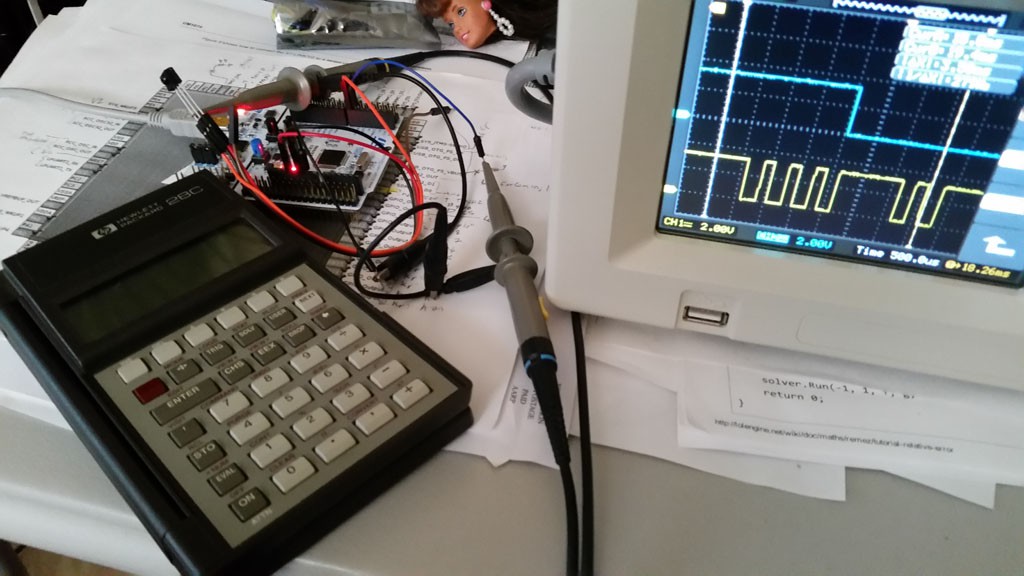
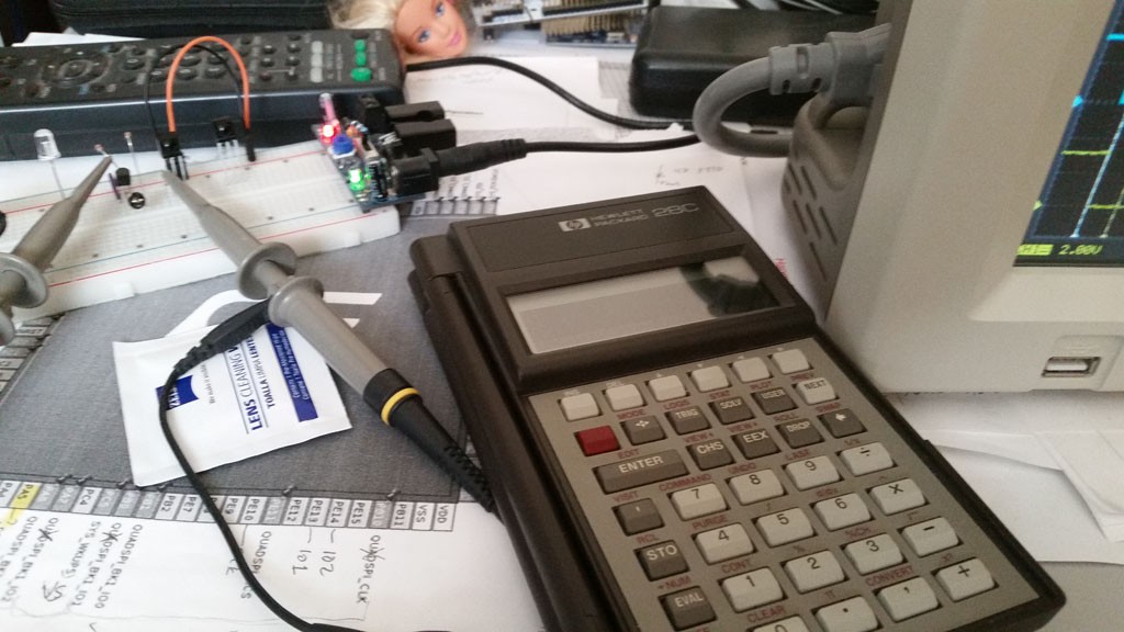
Obligatory bench shot:
![]()
OK, I mentioned two candidate approaches to demodulation in the last post. These were to work-around a deficiency in the detector during the initial signal reception. The first involved masking off processing for a period of time, then proceeding with decoding once the signal was believed to be stabilised, and the second involved decoding backwards from the end of transmission, instead of forwards from the front as a sane person would do. Being inclined towards insanity, naturally I planned to do the second. But the next morning I had a clearer head and decided to give Occam's Razor a KISS, and keep it simple until I could prove this entity needed to be multiplied out of necessity.
All that being said, my current approach now consists of:
- a state machine
- an IRQ handler for timer timeouts, and some APIs to set/cancel arbitrary timeout periods
- an IRQ handler for signal transitions
The state machine state currently include:
- 'hunting', which is looking for a period of continual silence. This is used to sync the machine with the signal. The spec dictates the stop condition of 3 half-bits of signal silence, so I use 2 half-bits in my implementation. This will let me validly detect any valid transmitted signal, and give me one half-bit time of fudge factor for timing jitter/overhead/etc.
- 'begin', which means the receiver is ready to start detecting. Ostensibly this is entered after a successful 'hunt' has completed.
- 'start', which is the mask-out period where the start bits come in. As mentioned, normally they would be received as distinct pulses -- and sometimes they are -- but the Vishay device has a tendency to at times merge them together (I think I've noticed some patterns, but more on that when I have done more experiments). Since I've been lucky that so far the observed merging happens only in the 'start' bits, which convey no information (well, other than one bit of information 'start happened'), I should be able to ignore signal during this period.
- 'accum', which is the accumulation of incoming signal transitions to build a datum.
Parts of the machine are implemented in the GPIO interrupt handler, and parts in the timeout handler.
I started out prescaling the 72 MHz clock by 2197 to yield a 32771.96 Hz clock, which is pretty close to the ideal 32768, thinking that this would make some of the coding easier, but I later noticed that some of my timing computations involved periods like 3.5 clocks, so I decided to divide by 1099 to make for a double-rate 65514.10 Hz clock. Then I can resolve those half periods when I want them. (I want them for when I want to sample in the middle of a burst, but maximize robustness against jitter, these bursts are pretty short in duration). As mentioned, the timer is sometimes used to trigger an interrupt on overflow, and sometimes used to measure durations by way of the current counter value.
The GPIO interrupt handler is currently set up to interrupt on both edges. Why? Just initial experimentation. I think I will wind up only using the falling edge in the end.
Currently, what I do is this:
- upon entering the 'hunt' state, set the timer to expire after 2 half-bit times. any edges detected in this state will reset the timer. If the timer times out, then we conclude that we are between transfers, and switch to the 'begin state'
- in the 'begin' state, if we see a falling edge, we interpret that as the start of transmission by way of the first burst. We set the timer to expire 3.25 half-bits later. This means that we expire once all start pulses are out-of-the-way, and in the middle of the burst if the first bit is a '1', or silence if it is '0'. The 0.25 half-bit delay sampling point should clear us from timing mismatch as much as practically possible. Any signal transitions during the 'begin' state are ignored. (I might wind up counting them for QA purposes later, though). Once the timeout occurs, I sample the signal level to 'synthesize' a signal transition that would have occurred beforehand hand pulses not been merged (if they even were, it only happens sometimes). This will transition to the 'accum' state. The timer is reset and a new timeout is set to be 1/4 half-bit past the last expected bit period. When this timeout occurs, we know the data transmission has finished, and that we are in the stop bit period. I chose 1/4 half-bit period to give a little insurance against timing jitter, a little time for any processing overhead, and plenty of time for 'hunt' to succeed between transmissions.
- in the 'accum' state, signal transitions will clock in bits. I have not implemented this yet. Also, when timeout occurs in this state, we conclude that the data transmission is completed, and can do parity checks, error detection/correction, and emit the received byte to whatever part of the system will be consuming it -- probably a queue with some sort of semaphore indicating 'data available'. I am expecting to use a scheme where I measure the current time (the timer's counter value) and depending on how long it was since the last transition, and whether the last bit is a 1 or 0, determine what this bit is. This should work because there is always 1 burst per bit period. This will make for 4 timing windows, which I have not yet calculated (4 because there are two bits -- the previous known one, and the current one being decoded).
As mentioned earlier, to help debug/validate my code, I also provisioned a GPIO line which I twiggle and can observe on the scope's second channel relative to the received signal on the first channel. Following are some traces that depict what I have described above. Channel 1 (yellow) is the Vishay module's output (and input to the board), and Channel 2 (blue) is the GPIO that I twiggle in my code at places of my choosing.
Overview Trace:
![]()
There are two data transmissions shown here. I set the code to set the GPIO high when I first detect signal, and when I have timed out at the expected end-of transmission. I set the GPIO low when I have exited the 'start' state/entered the 'accum' state. You can't see the 'hunt' state, alas, because I only have a 2-channel scope :(. But, since the board resets with that line low, you can at least see the entrance to 'start' in the first capture, and just take it as read that the other's work the same way. Anyway... in this trace you can see the chunk of time where the start bits are being ignored (the high time on the blue trace on the left), and where the accum state starts (the low time), and where the data transmission is expected to be over (goes back high), and the same process for the next trace (but not being able to see the intervening hunt state change to the start state, alas, because there are no twiggles to differentiate them). Also noteworthy in this capture is that the first transmission has merged the first two bursts and the next two bursts. The second transmission demodulates ideally, with all the bursts being distinguishable as one would prefer.
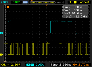
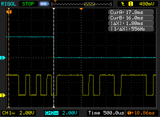
The next capture is a zoomed in version of the start of the first transmission:
![]()
Again, in this transmission the first two bursts of the start period are merged, and the last burst in the start period is merged with the first data-conveying burst. Cursor A shows where the timer times out (via the debug GPIO, shown on baby blue Channel 2), which is meant to be in the middle of the bursting period if the bit being transmitted is a '1', as is the case here. The computed ideal time for this is 1.388599 ms, and scope say 1.4 ms, so: great. This sample point will be in the middle of the bursting period if the first bit is a '1' (as it is here), or in silence if it is a '0'. Since we know that at this point we are meant to be 3.5 carrier cycles into the bit period, we know where we are and what signal we are supposed to have, so we can set up the decoder into a state as if we had a properly demodulated start bit period. You'll see later, but first I want to show the end of the signal for this transmission.
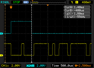
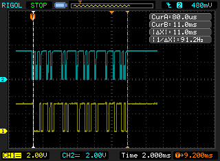
End of Transmission:
![]()
This is visually boring, but this is where the timer expires at the end of the 'accum' state. Cursor A is positioned on it, and shows 11.8 ms, which is close enough with the computed ideal of 11.74926 ms. As mentioned before, this is 1/4 half-bit time out from the end of the last bit's period, and into the beginning of the stop period's quiescence. In retrospect, I don't need to extend into that here, so maybe I'll alter the code later. (Because the last transition, if the last bit is a 0, will end 1/2 half-bit time before the bit's period ends, anyway.)
When this event occurs, we transition back into the 'hunt' state, looking for contiguous silence, and then transition into 'begin' where we look for the first burst in the next transmission.
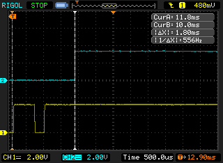
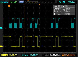
Here is the start of the next transmission:
![]()
As mentioned before, I didn't bother to reset the debug GPIO line going out of 'hunt' (I added that state later in the development), but take it as read that 'start' does begin with the first falling edge. The timer expires in the middle of the first burst of the data-conveying portion of the signal.
In this transmission, we were fortunate in that all the bursts were demodulated correctly, and we can see all the individual bursts in the start period (the first three). We can also see that the timeout in the 'start' state does hit in the middle of the first burst (if it is for a '1' bit), so: great.
Moving forward with this approach is warranted, I think.
Onwards:
I'm still waiting to receive the Blue Pill and the actual printer. The Blue Pill should be here in a few days. There is a bunch of coding I need to do on the decoder, and I have a great surrogate dev board with my Nucleo. Really, my great risk now is getting those parts in before I'm ready to receive them.
It's holidays where I am now, and parties will compete for attention, but I do feel compelled to get data decoded correctly. What I am hoping to do for my next test is to:
- decode data
- accumulate statistics of successes, signal loss, parity errors, recoverable errors, etc. Maybe convey them via some LEDs on some GPIOs, and fiddle with range and whatnot to see how reliable this thing is without needing to do a scope trace every time.
- build the next layer of software for this part, which makes this look like an input stream of bytes. Something like a notional /dev/irin if you like. Either way, close the book on bitfiddling with IR, and get on with building up the rest of the system
//end
-
Doleful Day -- IR Receiver Arrives!
06/30/2017 at 02:24 • 0 commentsSummary:
Happy news: my IR receiver modules (Vishay TSOP-4133) arrived today!
Sad news: they do not work perfectly
Hopeful news: I am pretty sure I can still make them work correctly and reliably
Deets:
My receiver modules arrived today. As mentioned before, the HP 'redeye' IR protocol is rather different in timing from the various conventions that IR remotes use, and I had a little challenge selecting a part whose characteristics have a hope of being usable in this application. I found one that was pretty close -- but not perfectly so -- and so I was eager to look at the output signals to make a pass/fail determination for the part.
For this test, I set up the module next to a trivial hand-rolled detector. My trivial crappy detector just consisted of an old (1970's!) FPT-100 phototransistor darlington-connected to a 2N3904 and some resistors. This detector is just so I can see the raw modulated signal next to the TSOP demodulated output, and does not have any of the goodies you would want on a detector for real use so I won't discuss that further.
Here is the obligatory bench shot:
![]()
I won't relate the details of the line encoding here, since they are well documented elsewhere. But if you don't want to search, and if these few words suffice, then consider it 'Bi-Phase-L' with the further modification that a marking half-bit time is actually conveyed as a burst for a quarter-bit time, followed by a space of a quarter bit time. Otherwise, it's the same. Here's a little graphical glossary of line codes:
And here is the first trace captured:
![]()
The CH 1 (yellow) trace is the TSOP demodulator, and the CH 2 (blue/cyan) trace is the raw IR signal from my crappy detector (the fuzz on the signal is the carrier, I had a lot of ambient light or you would see the carrier better, but I didn't care about that for this test).
The stuff between the cursors is 3-half-bit-times, all marking (oh, these signals are inverted, btw, so 'low' is 'marking'). As mentioned, this protocol is modified from conventional biphase-level in that a marking-half-bit-time is represented by a burst of a quarter-bit-time following by silence for the remaining quarter-bit time (a spacing half-bit is simply silence in both quarter-bit periods). I am guessing that this was done so that every burst will have a transition regardless of if you have two consecutive marks or not, but I really prefer my Manchester code the way the Mancunians intended -- it's already self-clocking, anyway. But, hey, not my spec...
OK, right away there is a problem. You can see that the first few bursts have been 'merged' into one output pulse. This is a bit of a disaster. I cried a little. But once I hardened my heart, and swallowed my tears, I noticed that the rest of the signal demodulated pretty much perfectly. You can see the whole byte when you zoom back:
![]()
So, what does it all mean? Well, my guess is that the unit's AGC was settling during the first part of the signal reception. Most IR protocols have a fairly juicy initial burst (or use long bursts in general), and this one doesn't; it instead goes into the regular timing but just with the illegal 3-half-bits-marking sequence. I further suspect that the rest of the signal demodulates correctly because AGC has converged by the end of the 3-half-bit time. So, maybe there's hope if, say, I were to disregard spurious transitions during the initial 3-half-bit-time, and carry on from there.
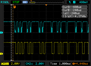
This is a little bit more wishful thinking that I prefer, so I took another sweep over a longer interval to gauge how reliable this hypothesis might be. This trace has 5 bytes in it, but I need to scroll them into view sequentially, so 5 images from the same trace.
Byte 1:
![]()
This one is different; it demodulated completely as expected/desired. Maybe because the AGC was still set up from the previous signal. This doesn't make me happy, though, because I like deterministic behaviour. But, it still suggests that the problem is tractable.
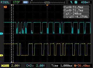
Byte 2:
![]()
Wahh! Now the 2nd-4th bursts are merged. Well, still the rest of the signal is fine if I can safely get past the first three bursts.
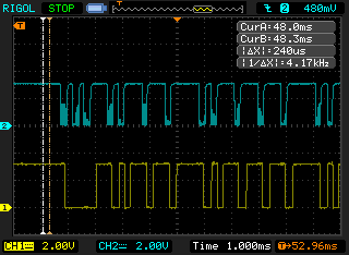
Byte 3:
![]()
Grr! Now all three initial bursts are merged!
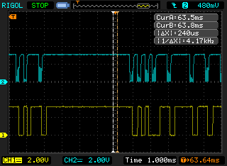
Byte 5:
![]()
Now the 3rd and 4th bursts are merged. Hrmrmrmrrr!
OK, so what can I do?
Well, one thing is I can give up, and go back and implement the IR detector circuit in discretes. But I'm just too hard-headed for that. Plus, since the signal looks so good for the rest of the transfer -- just the initial burst is a problem -- I am more impelled to carry on. So I have two ideas:
- I can try to lock out the spurious transitions for the first 3-half-bit-times and then be careful about sampling the first burst period, and carrying on from there. This should be doable.
- I can log transitions, and decode backwards. In a perfect byte transfer, there are 15 bursts. The byte transfer ends with 3-half-bit-times of spacing, so the end of the signal should be very easy to detect. If I were to log the timestamps of all the transitions, and reliably detect the end, then I should be able to decode the signal in reverse, at the expense of the storage of the transitions log. I believe I will have enough RAM to spare to support such a log.
OK, because I like to do things the hard way, I am going to make option '2' first attempt. I think it will be fun, and I think it might even prove to be the most reliable way, given the limitations of the IR decoder. After I get it working, I'll probably make some sort test suite (which means figuring out how to program this HP28C). If it doesn't work out, then I'll be back at the drawing board on the detector.
Onward...
For now I am parked again until my Blue Pill boards come in. I went and ordered some more that ship state side, so maybe I'll get those next week. If I get some time before then, I might try implementing the decoder on a Nucleo board I have, since that core code would port to the Blue Pill anyway, but I do have several other projects competing for my time, alas....
-
Torment and Torture by Tortuous Tools
06/25/2017 at 17:17 • 0 commentsSTM32CubeMX: "you are in a maze of twisty passages, all alike"
Brief soapbox advice to those new to that tool: it uses a 'progressive disclosure' style of UI design, and distributes pieces of functionality throughout the GUI. This can make it difficult to find something that you might think should be easier.
Case in point: I was trying to set up an interrupt on a gpio for the IR signal in -- pretty basic need, right? But I couldn't for the life of me find any options on the GPIO configuration for something 'mode = input with interrupt', nor any options on the NVIC for 'EXTI xxx'. Reference Manual says they're there though (and it would be shocking if they weren't). At length I found that what you must do is go to the 'pinout' page, and set the pin not to be 'input', but rather 'exti input'. Then the options on the 'configuration' page for 'gpio' will reveal the additional options of 'input, interrupt on rising/falling', and then the options will be presented on 'nvic' to handle the interrupt for that line. Whee! There's other 'fun' to be found, but I'll keep this post short(er).
So the lesson is: if you can't find something you believe is there, just shake the dickens out of the app until you hear stuff rattling around, and then look to see if maybe that's the piece you were looking for.
-- "I beat my machine; it's a part of me, it's inside of me / I'm stuck in this dream it's changing me I am becoming..."
-
Printing particulars
06/24/2017 at 17:16 • 0 commentsWhilst waiting for physical stuff to arrive, I have also started looking into this printer. As typical for things on eBay, you frequently don't get a data sheet with the item. This is listed as 'Aps Elm203-CH' compatible, so I'll try to dig that data up from somewhere.
In the meantime, it seems that this will probably be ESC/POS compatible from a command set standpoint (this is a common POS printer command set), so there will need to be some translation of the HP commands to ESC/POS. This shouldn't be too hard. What will possibly be more 'interesting' is that this printer has a different character set than the HP82240A/B, so I might wind up operating it in graphics mode and rasterize the text mode output myself. Hopefully I will have the RAM for that, but I think I probably will.
Another challenge is that the resolution of this printer is higher and incompatible with the HP82240 unit. This printer has 384 dots per line, and the 82240 has 166(?). So, even doubling the pix will still be 52 short, which is about 13%. I'll need to do some thinking and experimentation to see what looks best: discarding the extra 52, or stuffing dups in.
Lastly, the Devil is in the details, and sometimes items on eBay indicate something that is not entirely true. This is listed as serial RS232/TTL, which I hope is an accurate statement. The serial is a must in order for me to be able to use the BluePill board, and the TTL is important to avoid extra parts. And I hope 3.3V logic, but the pins should be 5V tolerant, I think....
-
IR Ire
06/24/2017 at 16:15 • 0 commentsThe HP 82240 uses a somewhat distinctive IR protocol developed in the 80's. I don't know what you would classify it as -- at first I thought it was 'biphase level', but that was a misinterpretation on my part. It does have some similarities to that, but the pulses are actually for 1/4 bit time, rather than 1/2 bit time. Another way of looking at it is that a marking signal is actually 1/4 bit time marking, and 1/4 bit time spacing.
I can appreciate the motivation for that: marks always have transition to detect their boundary, so a 0 followed by a 1 will still have a detectable transition, and because detecting the otherwise-illegal start sequence of 3 half-bit marks is easier. But, this does have a consequence: the pulse bursts are unusually short ('unusually' relative to the myriad of other IR protocols).
My hope is that I can use one of the Vishay TSOP IR detectors. This would be a boon for many reasons:
* cheap
* reduced component count (the whole thing is in a single 3-pin package with demodulated signal out)
* sophisticated: the unit includes amps, filters, AGC all in the unit
otherwise I will have to build the IR detector/demodulator from discretes&op-amps.
As mentioned, the major problem is that this IR protocol is unusual in the carrier frequency (32768 Hz -- wonder where that value came from? haha), and the timing involves comparatively short bursts followed by short quiescence.
The first part is not that big a deal because the parts typically have a fairly broad bandwidth -- I picked up the signal just fine on a part I have on-hand that has a center frequency of 36 KHz (TSOP4836), for example. The second part is trickier, though. On that same part the pulses were so stretched that the signal did indeed look like proper biphase level signalling. This cause me confusion for about a day when I was trying to do the reverse: to emit a signal to the printer. I couldn't see any significant difference between what I was generating, and my control signal generates by an HP-28C. But my signal would not print and the calculator's did. After several hours, I broke out a phototransistor and crufted a crappy detector together so I could see the raw modulated signal, and then it was clear that the TSOP was pulse-stretching. And it was all there in the spec, but you know how the brain and cognitive dissonance go, and I misinterpreted it as a standard line encoding that I already knew.
Anyway, Vishay has a ton of different parts, so I started rummaging though all the specs. The frequency part was trivial, they have a unit centered at 33 KHz, so that's solved. The timing was the tricky one. There are a couple more obscure IR protocols, such as RC-MM and RECS-80 and some Sharp that have bursts/quiescence of similar durations, and at length I found a part Vishay number TSOP4133 that just might work. I couldn't find any on eBay, so I ordered them from Mouser. Mouser will let you order just one, but you will be paying for shipping, so I usually order 10 of anything small like this. Who knows what I'll use the others for -- Christmas gifts, perhaps. Imagine mom's delight! Anyway, the upside of ordering from Mouser is that they ship quickly. I chose 'economy' shipping for this one, but I still expect that it will be here in the next week. Then I can test reception. I reeeeeally hope this unit works out..
-
Setting up build environment
06/24/2017 at 15:41 • 0 commentsIn advance of receiving parts off the slow boat from China, I set up my build system.
There's plenty of choices, but in the interest of simplicity, I have elected to use the various free tools from ST Microelectronics. You have to register a free account with them (they really don't send me any junk email) to get access to the tools. These include:* STM32CubeMX -- this is a 'wizard' tool whereby you define your board and it generates a skeleton project for various build systems. It's Java based, so it's slow as Christmas, but it is useful, especially when doing clock configuration for the more complicated devices.
* System Workbench -- this is an Eclipse-based build environment. I personally dislike Eclipse, and it too is Java based and slow as Christmas, but it really is convenient to have a complete toolchain that installs correctly out-of-box, and also to have a source-level debugger, so I put up with it. Mostly, I use this just to build and step in the debugger -- the bulk of my code authoring I do outside of it in Notepad++.
* ST-Link v2.1 -- this is the JTAG & SWD debugger physical interface. You will want this for debugging, and probably already have one if you have done any other ST development. There is a software package 'ST-Link Utility' that works directly with it. That is not critical, but I find it handy sometimes for simple chores like erasing the chip or dumping images from flash, or sometimes just sanity checking.
* All the usual docs: the Reference Manual, the Datasheet, the Errata, and any info I could find about the BluePill board, which is available from many sources on the Internet.
These ST chips typically have a factory-installed bootloader. It's somewhat of a pity that this one does not support USB, though, which means that folks just wanting to flash the pre-built firmware will need to do it over the UART, which in turn typically implies a USB-to-serial adapter and some soldering. Developers will probably prefer to burn over the ST-Link.
Today, I created my STM32CubeMX 'project' file based on documentation for the board, and guesses about where I will probably put my IO. I generated the skeleton project, and did a test build. This was just a sanity check, and to get a feel for memory consumption. I don't have any actual boards, yet, so I can't really doing any testing.
I'll probably carry on in the meantime by building some skeleton framework code for the low-level IR interface, and low-level serial printer interface.
HP 82240B IR Receiver and Printer Interface
This is an IR receiver and interface for adapting a commodity receipt printer to be 82240B-compatible.