-
The Scrobby on Kickstarter!
09/11/2014 at 08:12 • 0 commentsIt's been a touch quiet here, but not for me! I've been working on getting things ready for the next step in this project: Getting ready for production. I like the idea of Kickstarter from the start, the idea of combining testing your product's market reception with getting this crucial bit of early stage financing is very appealing. Usually financing in this stage is based on best guesses based on the appeal of the product and market position tools (patents, etc). Kickstarter and similar ideas allow you to gain real world feedback from a much earlier stage.
So, without further delay:
https://www.kickstarter.com/projects/stefanhamminga/scrobby-solar-keeping-your-solar-panels-clean
I hope you'll have a look and maybe even become an early adopter!
-
Assembling the rest of the bottom unit
08/20/2014 at 11:01 • 0 commentsSo below some more bits on the mechanical assembly, the internal layout of the spools and drives.
![]()
![]()
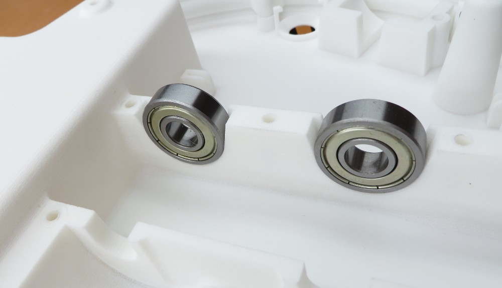
Bearings fit just fine.
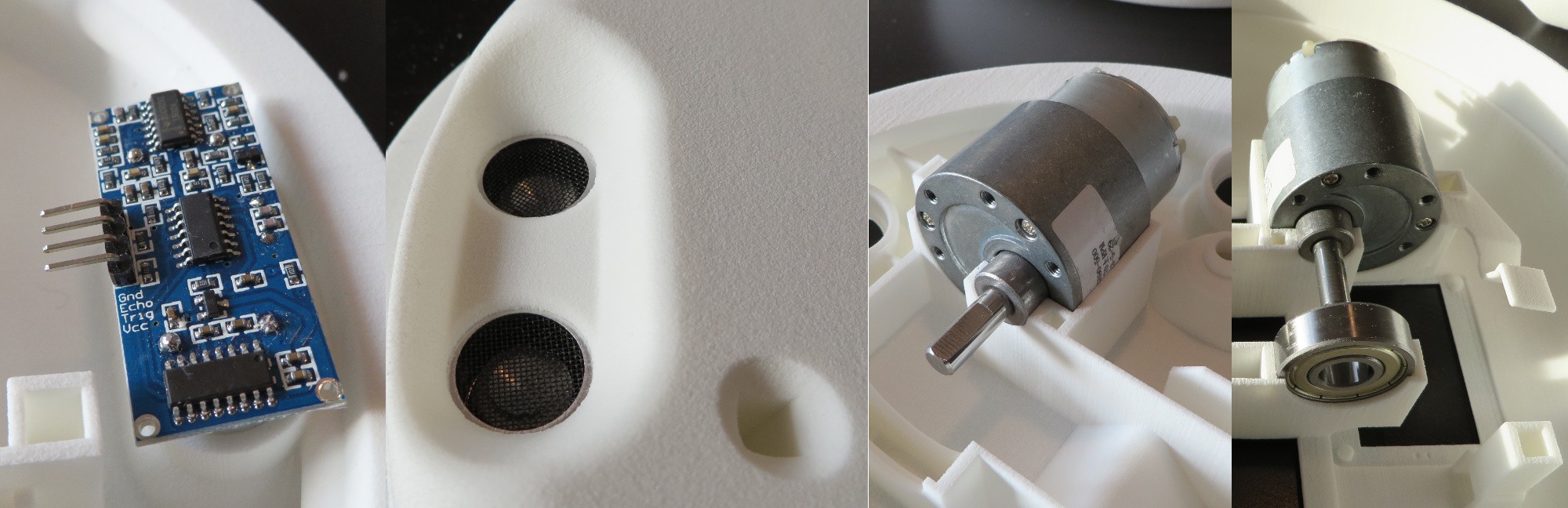
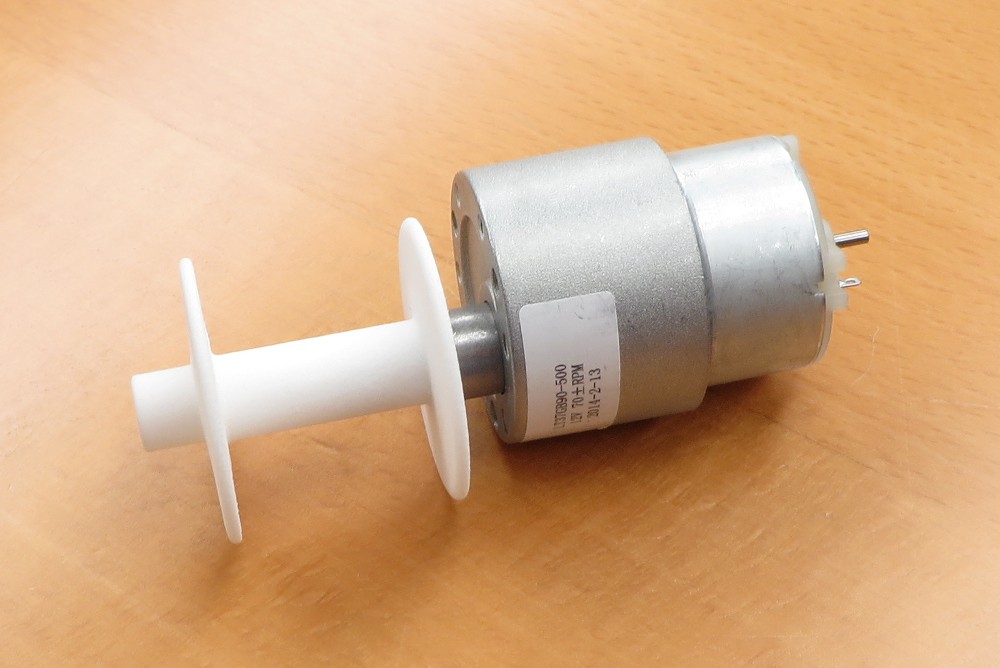
![]() I chose these 37mm DC motors for the prototype because they are available off the shelf in a decent amount of ratios and power ratings. They seem to be pretty sturdy as well. The relatively low power density keeps them from overheating under continuous use.
I chose these 37mm DC motors for the prototype because they are available off the shelf in a decent amount of ratios and power ratings. They seem to be pretty sturdy as well. The relatively low power density keeps them from overheating under continuous use.The plastic spools will carry up to 50-80 meters of 0,5mm Dyneema wire and are slightly offset, the rear spool axis being closer to the top of the device.
![]()
-
Bearing system fitment testing video
08/20/2014 at 10:26 • 0 commentsA quick video showing how the slewing bearing system works.
-
Mechanics for prototype 2
08/19/2014 at 20:55 • 0 comments![]() Before heading into the electronic designs I'd like to go over the mechanics of the second prototype and the changes made. I think it'll clarify some of the demands put on the electric designs I'll be discussing later on.
Before heading into the electronic designs I'd like to go over the mechanics of the second prototype and the changes made. I think it'll clarify some of the demands put on the electric designs I'll be discussing later on.As you can see to the right, I've been having quite a lot of fun trying it out.
Lets start with the new parts (with prototype 1 in the background):
![]()
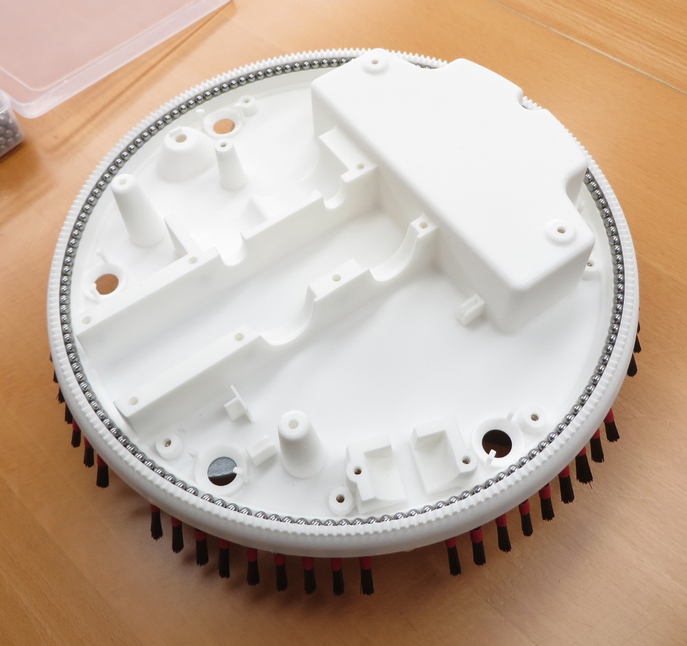
![]() I've split the design into parts with more consistent wall thickness (crucial for the injection moulded parts). The brush bearing race is now a 3 part affair, with the bottom quarter in the bottom shell, the inner top quarter a separate part (just below it) and the outer race still in the slewing ring.
I've split the design into parts with more consistent wall thickness (crucial for the injection moulded parts). The brush bearing race is now a 3 part affair, with the bottom quarter in the bottom shell, the inner top quarter a separate part (just below it) and the outer race still in the slewing ring.The main reason for doing this is that, while the previous bearing design worked very well, it was a real pain to assemble. The split design allows me to just drop in the bearing balls, instead of many minutes prying them through the small opening.
With the split design the bearing is still nearly completely sealed, only the drive gear has an opening (which will be shielded in production models, but allows for much easier part exchange here).
The top shell is now just an empty shell, there is a separate piece to clamp down the internals. This makes life a lot easier in both assembly and stress on the outer shell.
If you'll be doing a lot of taking things apart and putting it back together, get some of these:
![]()
They are sold by the 100 on eBay, named 'Metric Thread Brass Knurl Nuts'.
-
From bits to box, the 3D prints for prototype 1
08/19/2014 at 13:25 • 0 comments![]() I'm going to kick off this project documentation by showing you some, hopefully, interesting details about the mechanical parts, the 3D printing work and putting it together.
I'm going to kick off this project documentation by showing you some, hopefully, interesting details about the mechanical parts, the 3D printing work and putting it together.As I said: from bits to box!
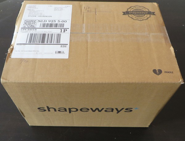
My preferred place for print work is Shapeways, they generally do very nice work.
![]()
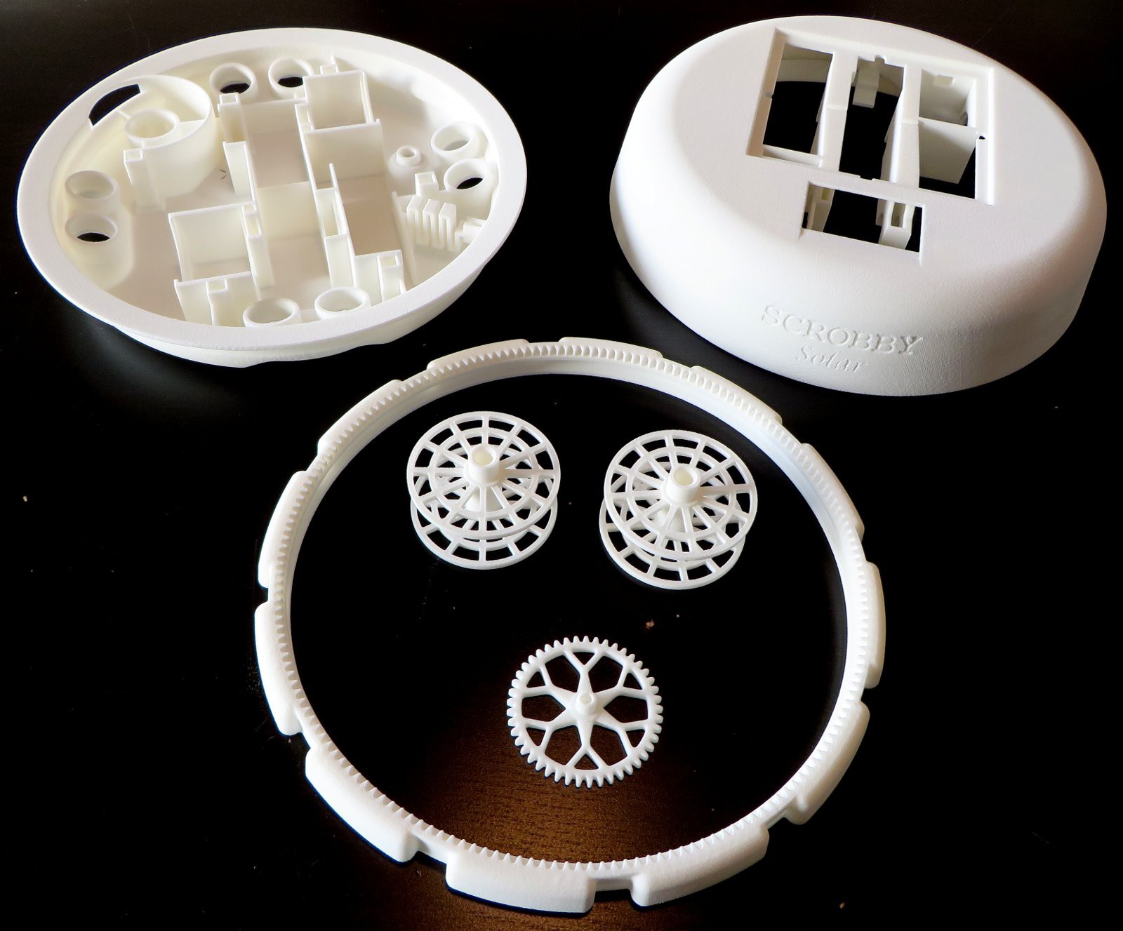
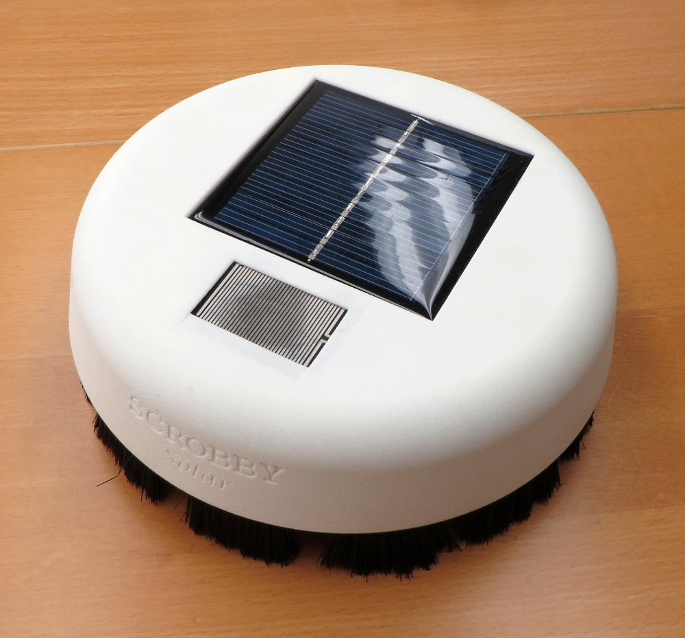
The first prototype of the Scrobby Solar consisted of only five 3D printed parts, as shown on the right. Top left is the bottom half of the shell, with the top half next to it. The larger centre part is the main brush. This is what will do the cleaning, plus it'll be what the robot rests on... Look mommy, no wheels!
The part is actually a miniature slewing ring, including a gear and bearing race.
Shown inside the slewing ring are the two spools for the tether wires and a gear to drive the slewing ring.
![]()
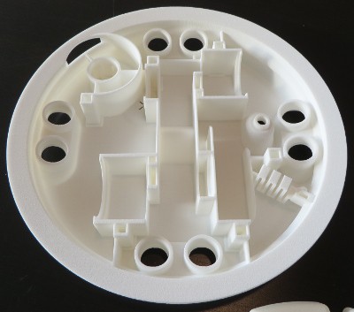
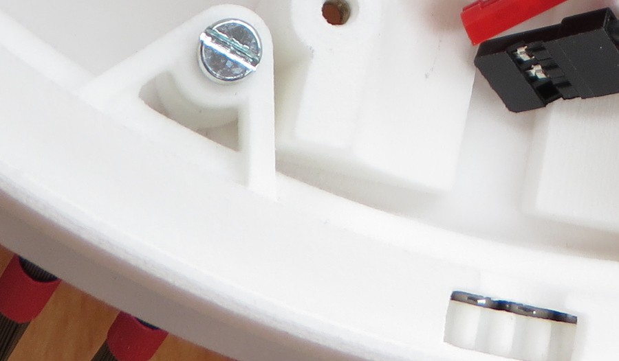
The bottom shell in some greater detail shows how I used square shapes for the non essential surfaces, in order to save polygons for the round faces (the 1M poly limit at Shapeways). In the bottom right is a small zigzag bit, this is a sprung opening to the raceway to allow inserting the bearing balls. Afterwards a 2mm pin can be inserted to hold it into place.
It turned out the fitment was quite spot on for most part. The holes for the ultrasonic sensor were modelled 0,15mm oversized and turned out to give a nice snug fit. The motors were a tight fit though, so after breaking out the callipers it was found the model had been printed to scale on two of the three axis, but a bit undersized on the 3rd (about 0,3mm per 100mm). No worries though, the device still fit together nicely.
![]()
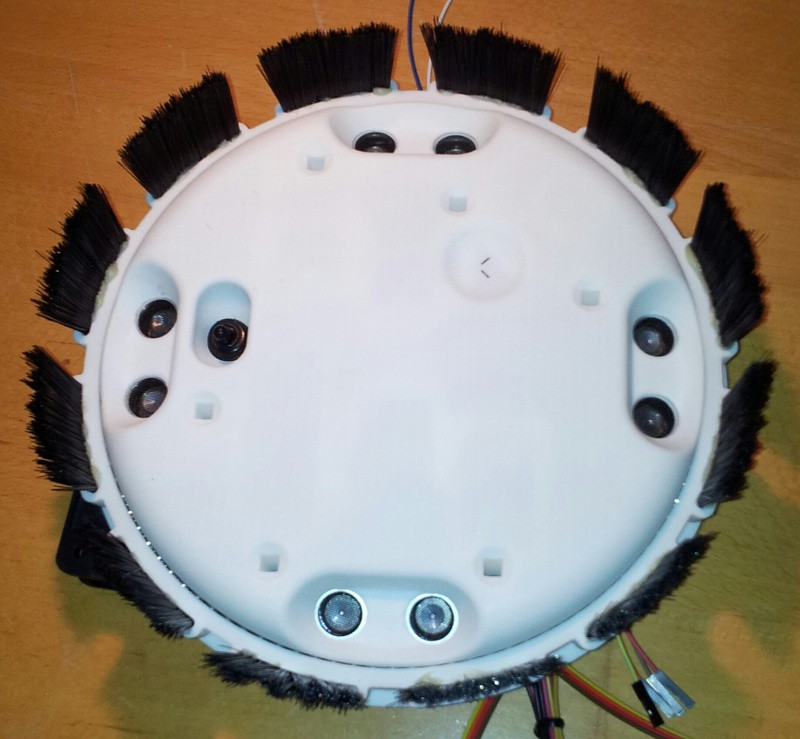
And this is what it looks like from the bottom, after painstakingly glueing all those little hairs in (took me a day the first time, pfew)...
![]()
![]()
Scrobby - a solar panel cleaning robot
Creating a small, autonomous robot to keep solar panel installations clean.
 I chose these 37mm DC motors for the prototype because they are available off the shelf in a decent amount of ratios and power ratings. They seem to be pretty sturdy as well. The relatively low power density keeps them from overheating under continuous use.
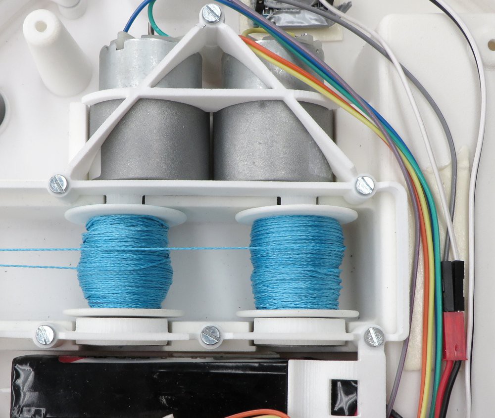
 Before heading into the electronic designs I'd like to go over the mechanics of the second prototype and the changes made. I think it'll clarify some of the demands put on the electric designs I'll be discussing later on.
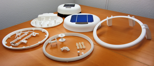
 I've split the design into parts with more consistent wall thickness (crucial for the injection moulded parts). The brush bearing race is now a 3 part affair, with the bottom quarter in the bottom shell, the inner top quarter a separate part (just below it) and the outer race still in the slewing ring.
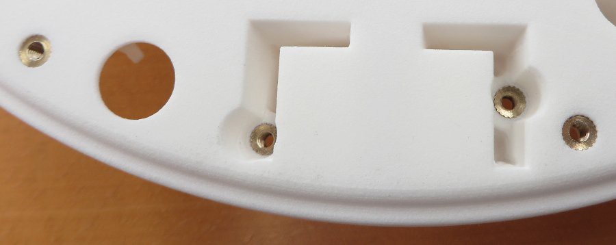
 I'm going to kick off this project documentation by showing you some, hopefully, interesting details about the mechanical parts, the 3D printing work and putting it together.