Dan DWRobotics
-
Micro Log, Tappy Legs and GUI crouches
06/04/2018 at 21:42 • 0 commentsTonight's efforts have been centered around experimenting with different control methods.
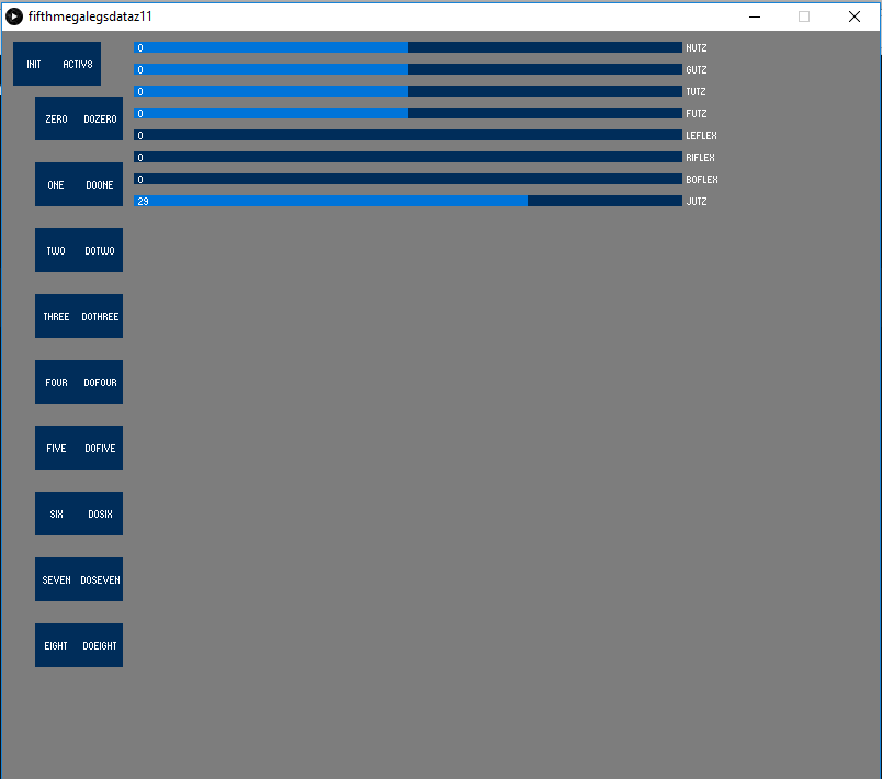
My GUI is still pretty basic. But I have big plans for it. At present the sliders affect various sets of joints by adding or subtracting amounts to the leg positions. The slider labelled 'Boflex' is the one seen in the video above which makes the legs crouch and rise up. It's a long way from inverse kinematics, but it's the start point. The idea of these movements is to create a set of movements that can be used in conjunction with each other to make more complex movements. When I have found the best movements to combine, I will create a 'sequencer' on the GUI where I can pick various preset movements and play them back in a sequence to make my first 'walk'.
The squares give me the option to remember a movement by pressing teh number and then replay that movement by pressing the button next to it.
The slider labelled 'jutz' at the bottom controls how many steps there are between each movement. So if I select 10, the code will work out the difference between teh current movement and the next one and then divide it into ten steps, which plays back quite fast. If I select a higher number the movement plays back much slower because there are more steps between each movement.
Eventually I will program some buttons which can apply acceleration 'curves' to each movement so that I can make it speed up and slow down between two movements. This should help reduce the jerkiness of the movements and make them more lifelike. One of the issues of having a constant rate of movement is that sometimes the set point and current position oscillate around each other causing more jerkiness.
The above video also demonstrates the very first and miniscule movements conducted while balancing on one leg. They are tiny, but showing that this is possible is extremely important if they are ever going to walk! It also demonstrates the power of the joints. Without a counter balance in the form of arms, the legs in the tappy motion are using a huge amount of force to keep the waist level.
-
Finally, back at the Programming Stage
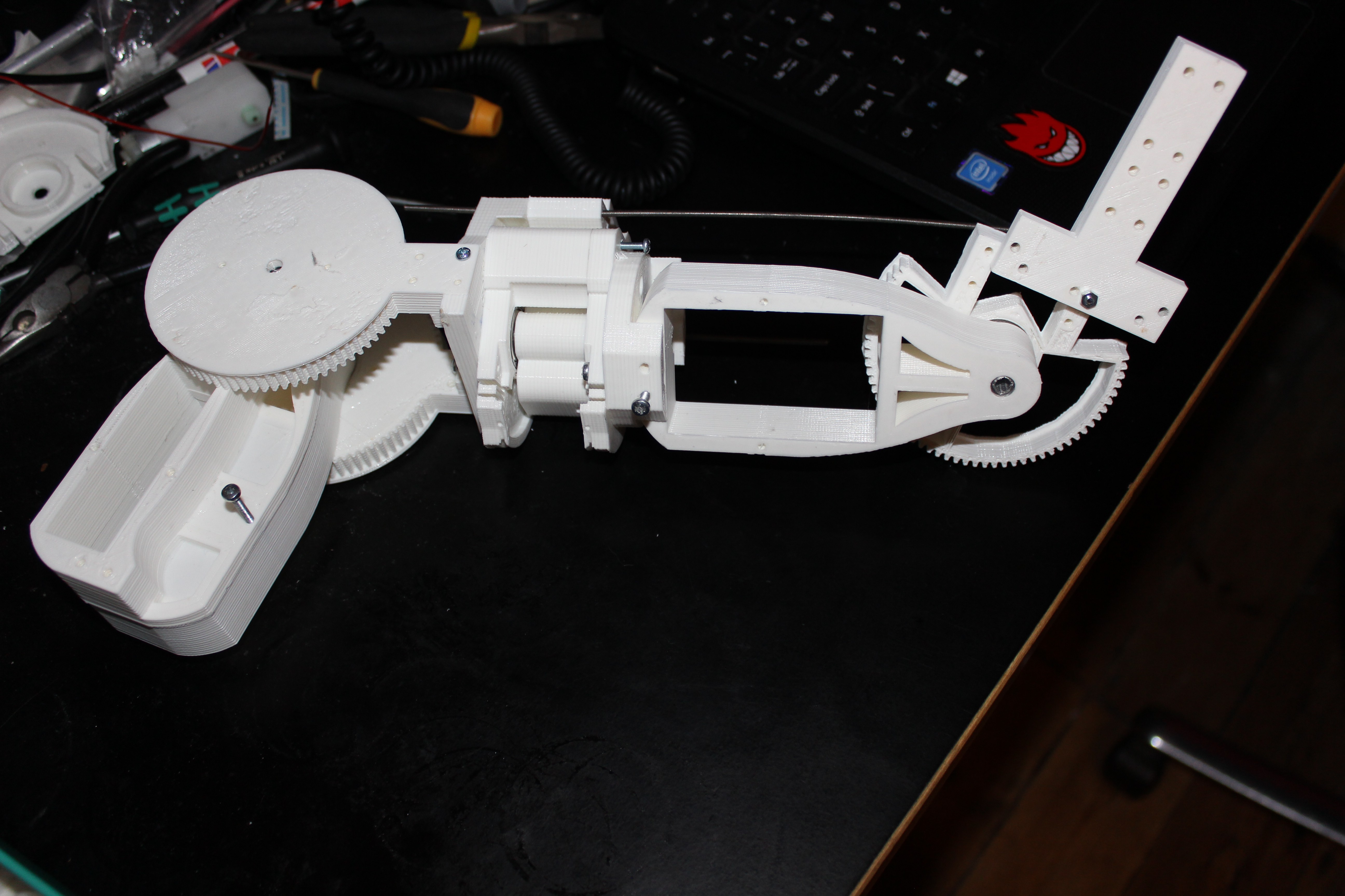
06/04/2018 at 01:48 • 0 commentsAfter an arduous and long process of completely redesigning my legs I am finally back to a stage of testing and programming. I spent quite a large amount of time wiring everything up. I designed a new housing for the potentiometers which uses a pre-made dupont style pin header connectors to plug the potentiometer directly into. This design was to speed up the install of the pots, but also to address the limited lifespan of potentiometers. When they wear out they can simply be clipped out of the housing and a new one slotted in, without the need to solder.
The new design is pretty sturdy. Still a few minor bugs I need to work on with the potentiometer feedback. Interestingly I wouldn't have dreamed of doing my first crouch tests on a carpet but the feet are now big enough to give some leeway when it comes to the thing balancing. A short video, but many more to come:
-
Mark II legs, Now standing around
05/07/2018 at 23:28 • 1 commentI just couldn't resist posting an update up to show the progress of the 'Mark II' legs design.
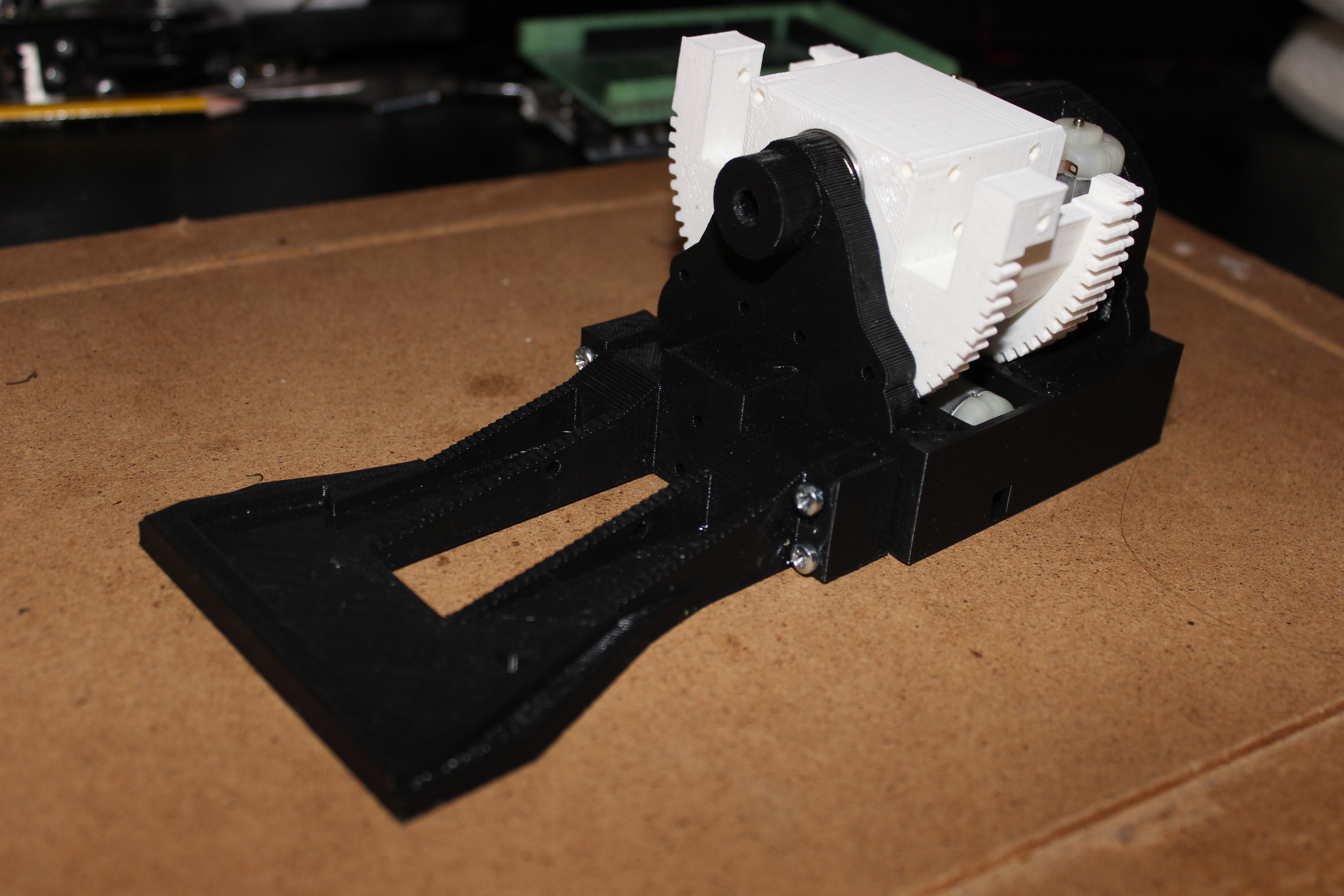
Spent much of the weekend printing and designing. I also started prepping and soldering the electric motors for the legs. I was keen to see how rigid the structure is with the new pelvis and have not been disappointed. It is a long way from walking anywhere but the leg is very rigid, even with no power to the motors. Picture demonstrating standing up on one foot, so to speak:
![]()
As expected, the new gear ratio is lovely and smooth when I drive them directly with a battery, but the leg will still be able to move fast enough to walk and do all the normal things a robot might want to do, such as gangnam style. Actually my robots will never be reduced to such buffoonery.
-
Big Parts and more re-designing....
05/02/2018 at 21:59 • 0 comments![]()
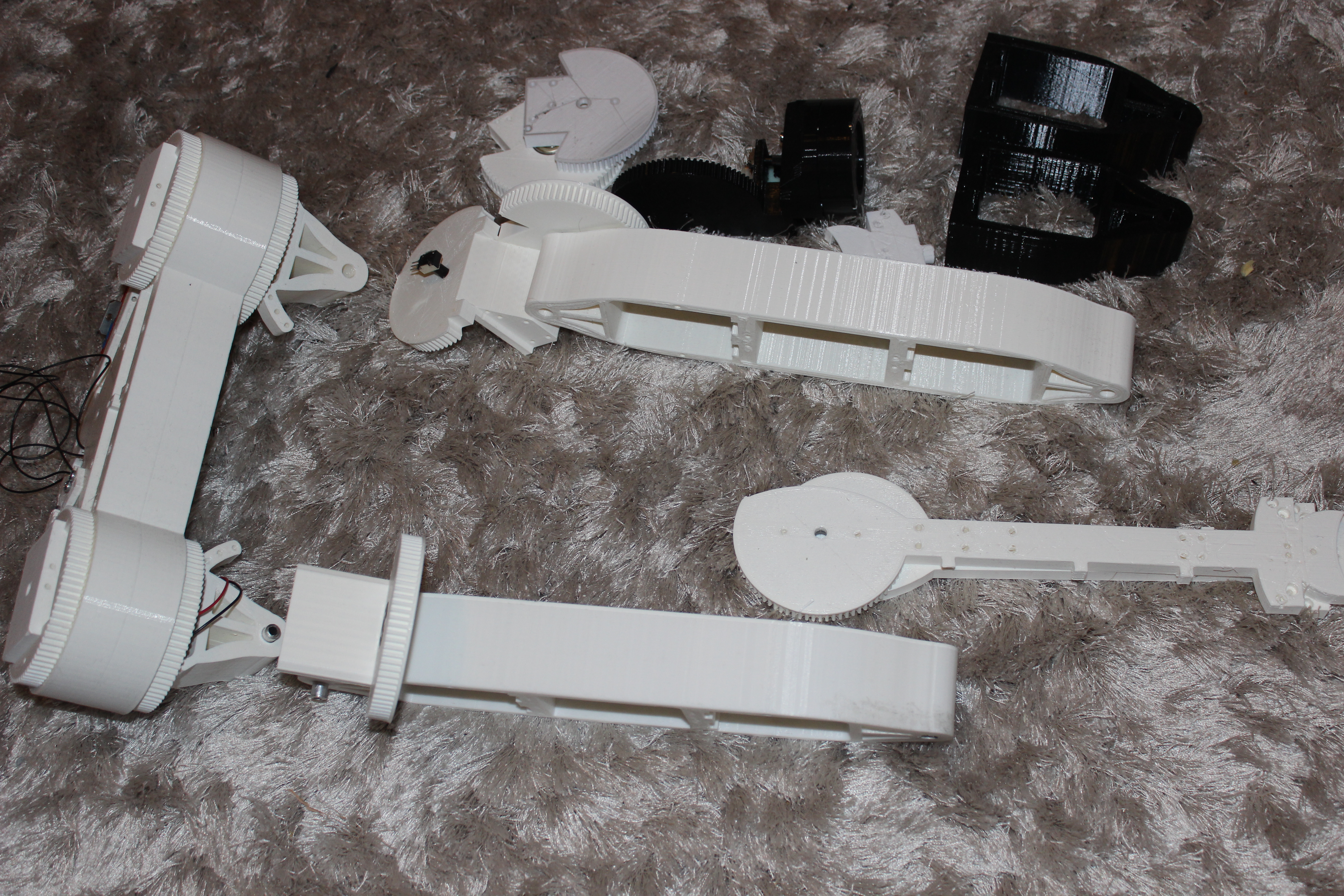
I am now feverishly printing parts, big parts. The above picture shows the new pelvis and the new 'Femurs' which are all now printed in one piece where they had previously been multiple parts bolted together. This reduces the complexity of the build and should ultimately lead to more rigidity in teh frame.
I've taken many of the drawbacks from the previous design and rectified them. The first thing that was annoying me about the previous design is that I tried to make human proportions to the joints, meaning I made the lower leg slightly shorter than the upper leg. This had the unintended consequence of making movements quite de-stablising to the whole structrue. My maths hasn't quite gotten to full body kinematics and so the new designs has these two parts of the leg as teh same length meaning moving between standing and crouching should be much smoother and less wobbly.
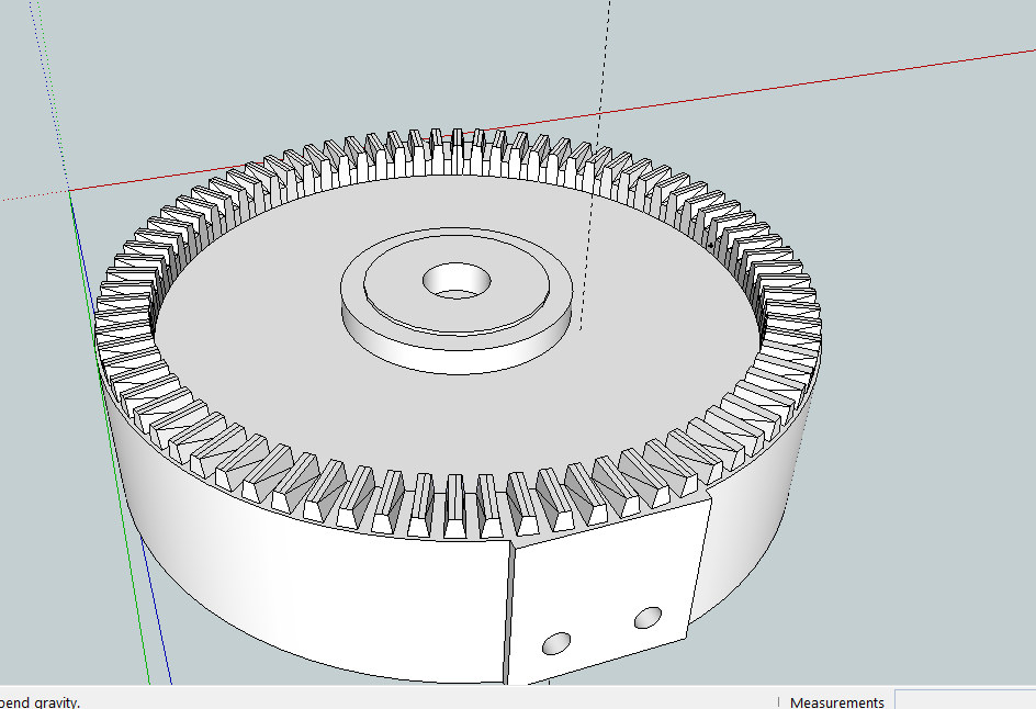
One of the other real key things I did was to redesign the cog ratios to give more torque and slower movements. This should have multiple benefits. Firstly, this machine is going to be STRONG. The extra torque is required as I am planning to add a torsoe, arms and a head. All will be fully motorised and so the extra weight will be substantial. The second major benefit to the new cog ratio should be smoother and slightly slower movements. Whilst I did like the fast response of the previous model, it was slightly too jerky and weirdly I actually need more mechanical movement at this stage, rather than human-like fast movements. I've gotten to know my new CR-10 and the extra build plate size really allows me to design much bigger parts, which is simplifying the build. Previously I had made small parts and bolted them together but the large print size and the success rate of the CR-10 means that I am not afraid to do big parts such as the pelvis below.
![]()
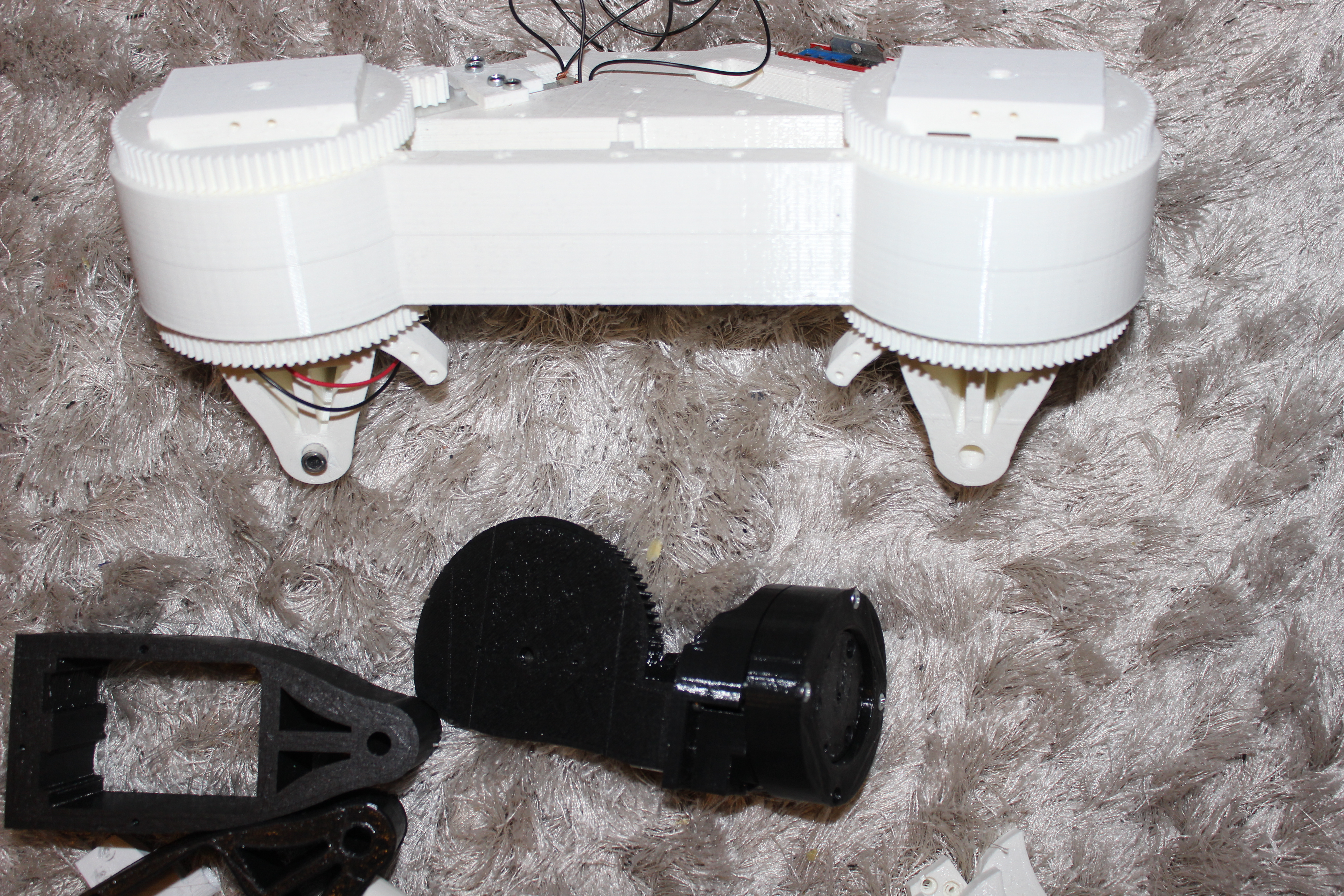
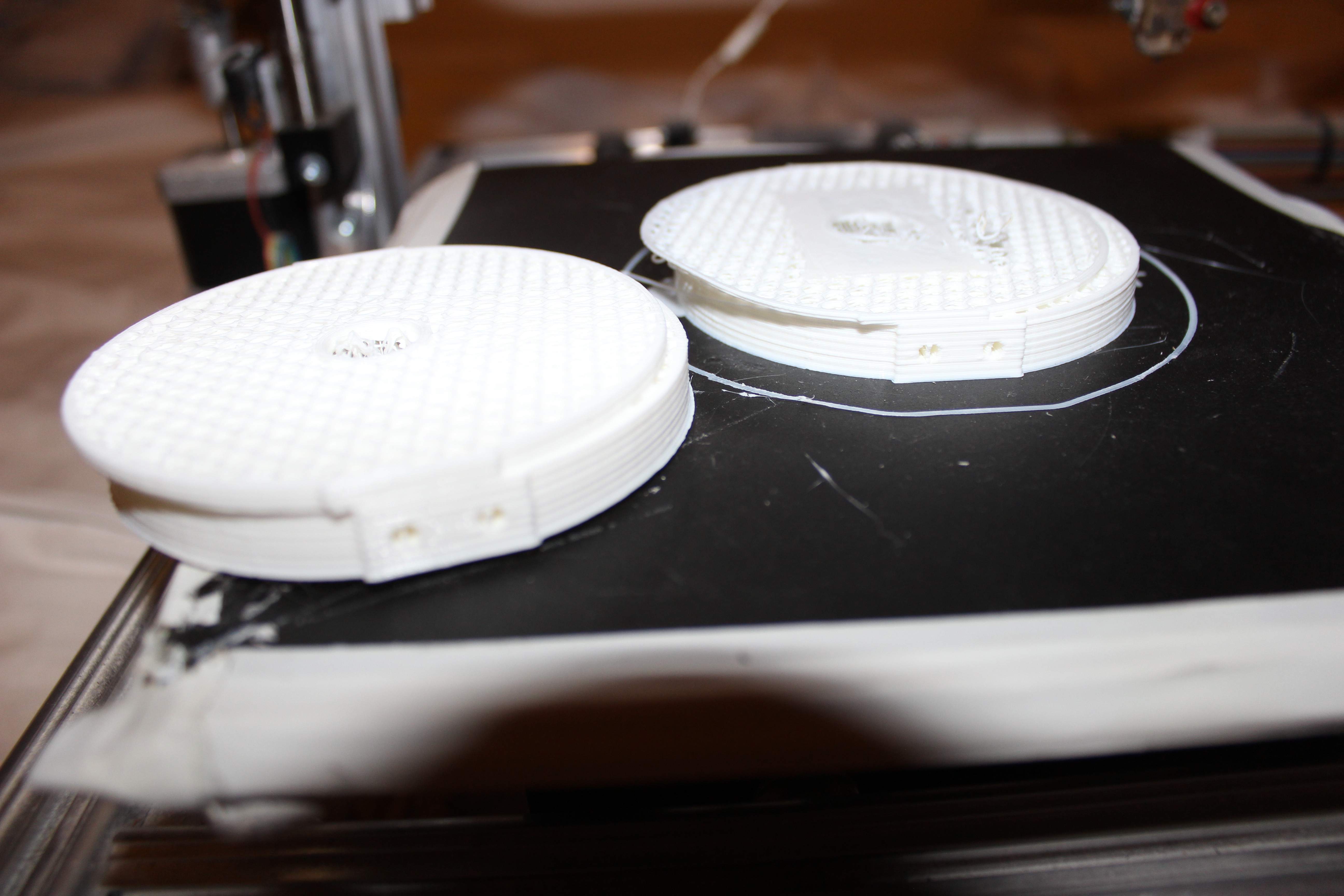
Above is the pelvis. Most of the parts don't have motors in yet. I am trying something totally bonkers and using the plastic on its own as a bearing. So the bearing is basically two massive printed barrels inside each other and the bearing relies on the plastic parts sliding against each other. This will work because the motors have a large amount of torque and the hip 'yaw' mechanism does not need a lot of torque. Previously I have inserted skateboard bearings into joints which is great for most applications, but for the hip 'yaw' or swivel mechanism this part needs to be very rigid as any 'give' in this joint is amplified along the length of the rest of the leg creating instability. Suffice to say, the joint is now incredibly rigid.
![]()
Then this is 'foot' mark II. It doesn't look like much, but I wish I could demonstrate how smooth and powerful the 'Ankle Roll' mechanism is. It is ridiculously strong, but when it is operating it could potentially need to resist the whole weight of the body when making any movements where teh body sways left and right, i.e. during walking, shifting the centre of balance between left and right foot. The toes are minimalist at the moment but the whole front section screws off so if I want to update those later I can. I am planning to attach four flat Force Sensitive Resistors to the base of the feet with some kind of rubber cover. This should provide some shock absortion and give a more uniform amount of force onto the FSR's so they are not just sensitive in their own spot.
![]()
I'm sure you all know, but I can't tell you how long it takes to design this many moving parts. Usually after a long day at work I will get home and start printing and work on the designs so it pretty tiring and I often need to force myself to get something substantial done. I still have a large amount to design, arms, hands and upper body. -
Miniscule Update
03/28/2018 at 21:05 • 2 commentsJust wanted to add a very quick update. I took a break from working on this project for a number of reasons, but I have been preparing to ramp up progress on this over the last few months. I had a crushing realisation that I needed to completely redesign the legs if they are ever going to walk and the prospect of spending that much time on something I had already done was very disappointing. Basically the legs need to be mounted into the waist completely differently to prevent wobble as the structure was not rigid enough. Basically any YAW type movements on my machines have proven to be difficult to build at home, but i think I have overcome this with a very sturdy design. I also bought a CR-10 and had to get used to the settings. The parts I print can't be done at the usual pace because they are too large and each joint would take weeks. I now have some great settings and am currently redesigning the cogs for the large joints. This is to give them greater torque and a smoother more controlled motion. This should help with stability and make programming walking easier. I am also happy that the CR-10 can print larger parts which means I can combine parts in one print rather than bolting parts together. This will also lead to a greater rigidity as there will be less joins on the legs.
I hope to post some real updates after the long weekend. Just wanted to make sure anyone who is following knows I am still designing and printing :)
-
Really need a hand...... Pt1
08/26/2017 at 13:59 • 2 commentsWell, thought I would share the progress with the hand. Hadn't really predicted quiet how complex a task it is to design a hand from scratch. It is still in its early stages of conception, but the design is starting to look pretty badass, so I thought I would share. What you can't see from the snapshot is that there are a ton of internal tunnels which allow the cabling to be run for transmission of motion from the motors in the forearm. These tunnels and the points at which the cables have to change angle or need to bend needs to be very carefully thought out, otherwise when you move the wrist the fingers would change position for instance. Nothing new there, although there are two cables for each finger, so that instead of a spring action pulling the fingers back to extension the action will be actively driven. Lots of hand designs I've seen use a spring mechanism to open the fingers but I want the fingers to be stable in both directions in case an action requires it.
![]()
I'm close to printing now, but I know that there will be lots and lots of design revisions until the final version is realised. The angles and mechanisms are all estimated, I actually have no idea if they will work out. But from the first print I can test and make decisions based on what works and what needs changing.
-
Goofy Drawings and failed parts...
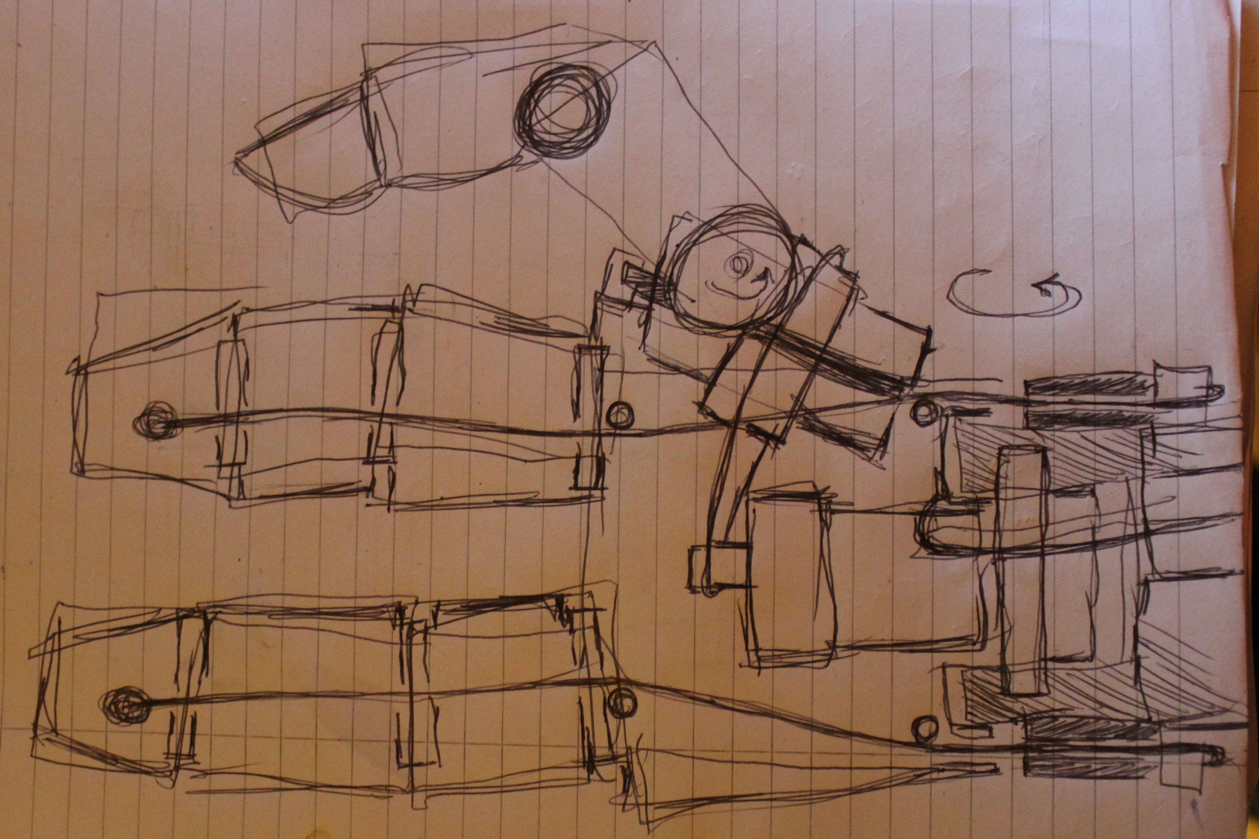
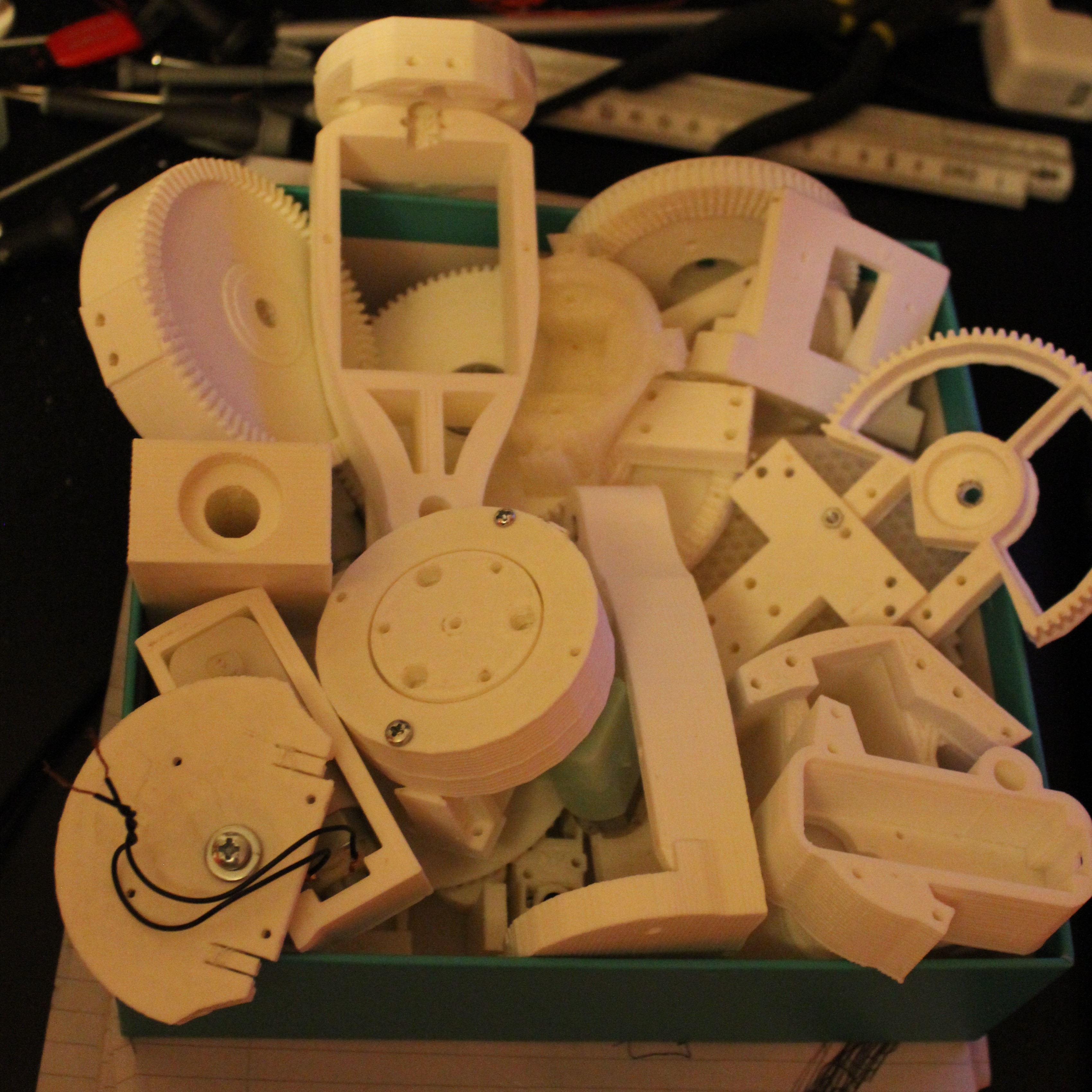
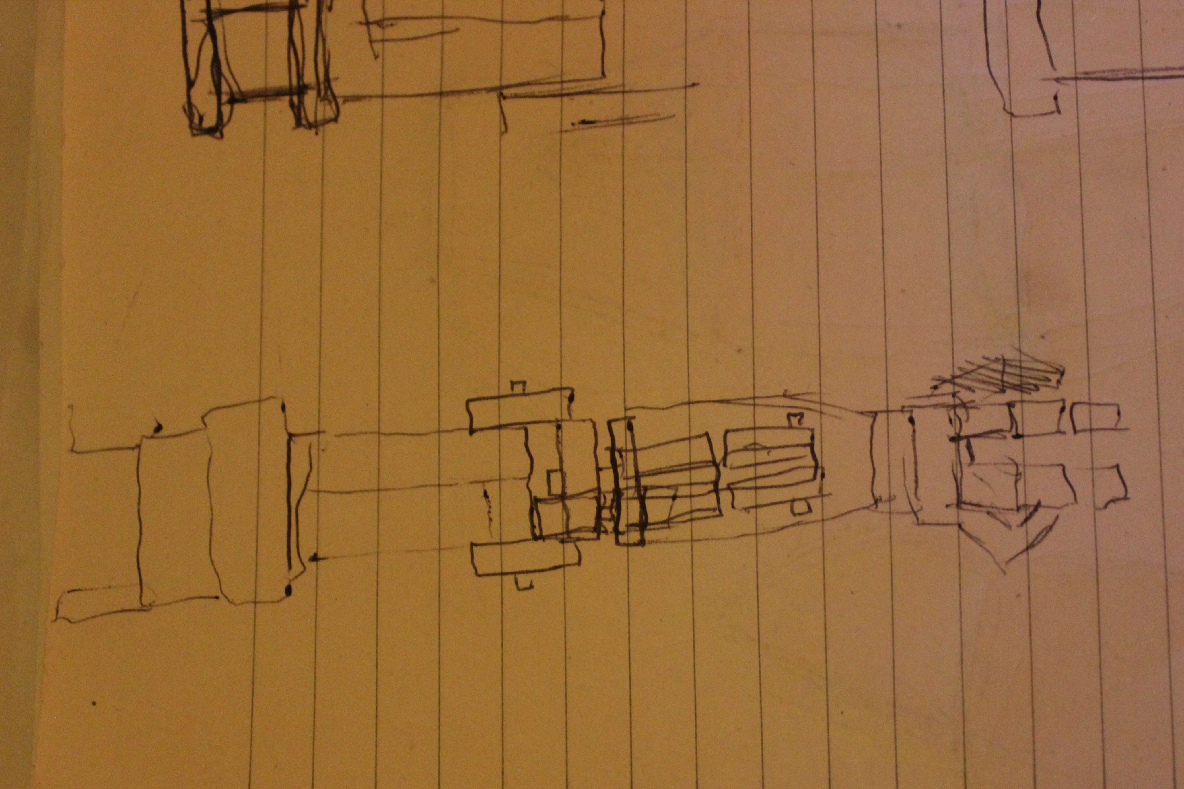
08/22/2017 at 21:20 • 6 commentsI guess it is worth at least once showing the very basics of designing a completely new device. Often you can do this in your head. I do this, usually when I am supposed to be asleep but just can't get a particular problem out of my head. Or many times you can do this directly in your CAD program of choice. But sometimes, and in fact many times, the very starting point is
........................... the rubbish drawings.
I have hundreds of these. Some I come back to again and again, to inform the later design process. Many times, there is no quicker way to decide which cables, cogs and axles are going where, than by just trying to draw it out on paper. So to break the monotony of actually designing the hand in sketchup, I thought I would take a break to share to the utterly ridiculous 'concept' drawings that eventually lead to solid printed items and the many rejected parts I have printed over the last couple of months.
![]()
![]()
![]()
-
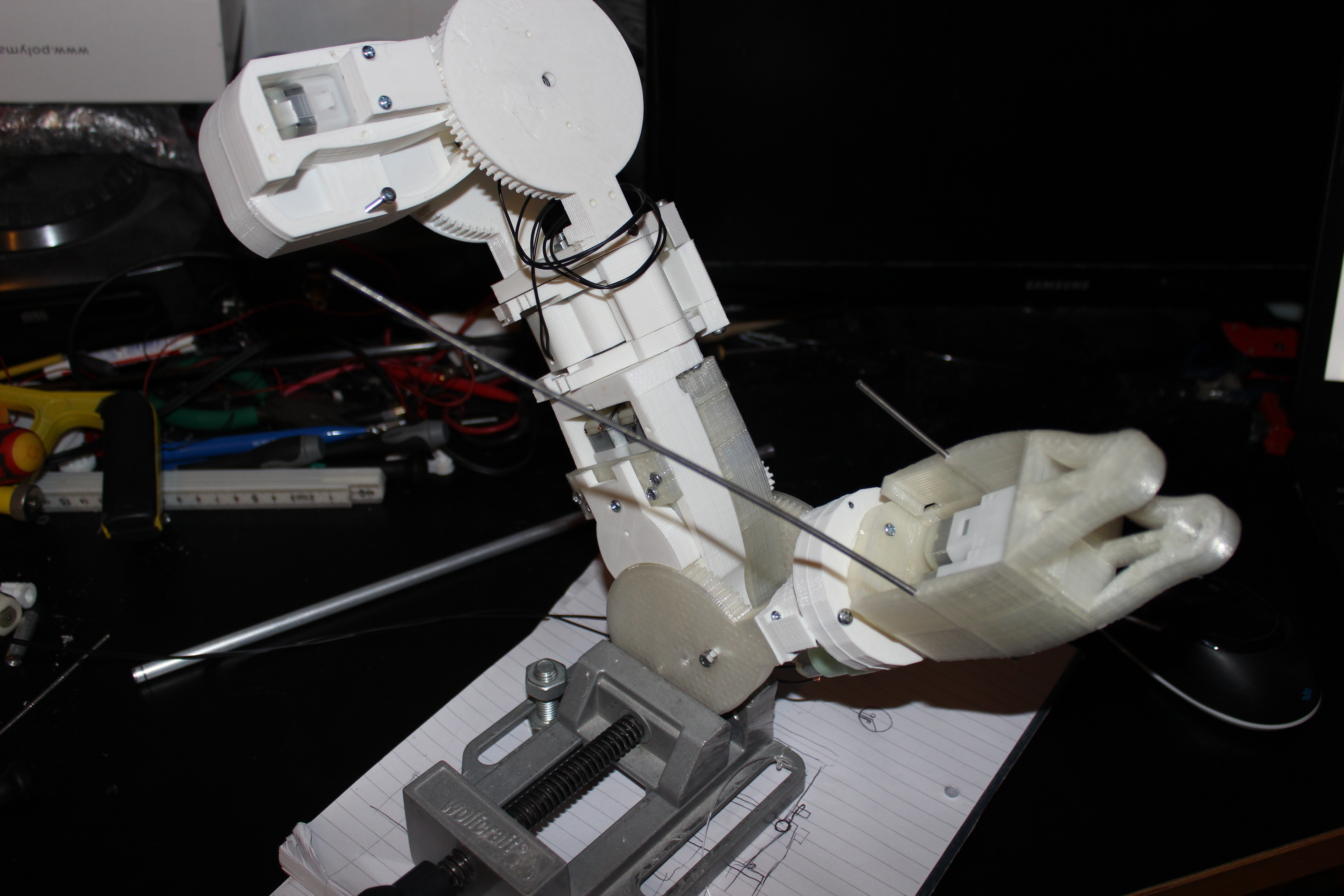
Arm is starting to take shape
08/20/2017 at 20:04 • 0 commentsSo I have been working a huge amount on designing the arms. I needed to make sure I get all of the articulation required but retaining some semblance of the human form factor. I decided I was not going to be able to have a five fingers but will have to go with two fingers and a thumb. My local print shop ran out of 3mm White PLA so I had to continue printing in 'natural' which I don't like as much, but never mind. Let me know if you can't see the video below, I forgot I had music on for this one so it is copywrited.
The arm has a Yaw in both the upper arm and the lower arm. I had to design a new planetary gear for the lower arm yaw. I like it so much I will probably redesign the upper arm to use this same yaw mechanism. I spent a lot of time debating whether I need a wrist 'pitch' and I have ultimately decided that I do need it as it is key to being able to pick things up and do other tasks in a human-like manner. So I now have a decent idea of how the hand will work and look but just need to design it. The hand is going to be designed to be strong enough to handle every day objects. I think if it can't crush a beer can, then it is not strong enough. Ultimately I want it to be able to pick up things like a drill or a shopping bag etc. It does look quite simplistic in design, but an incredible amount of thought has gone into the design to make this work.
![]()
The fingers and wrist pitch will be 'cable pulled' like many other designs out there and I am planning to have one motor in the hand to pull the thumb inwards to the centre of the hand for grabbing. So the thumb will have two actuators to enable it to do what the human thumb does by either opposing the fingers to pinch or keeping the thumb flat and making a kind of fist shape.
-
Humerus - Humourless more like.....
08/07/2017 at 21:58 • 4 commentsSo, no updates for a while. For a very good reason.
I have been fighting with the design process. Really slogging away, forcing myself to endure days of staring at a screen making measurements and generally trying to animate the mechanics in my head. I had to create a whole new method of driving the joints, using cables instead of large cogs. This gives me the ability to make high ratio differences whilst maintaining the ability to make the parts printable. ( There is a minimum practical size to 3D printed gear teeth.)
This is specifically required for the upper arm Yaw mechanism which needs to be small form factor but high power and relatively low speed. I have gone through about 50 iterations of this mechanism, each time having to wait hours whilst my parts print.
Each time I change the design I also need to redesign how I am going to get position feedback, which is actually quite difficult to design in pre-emptively.
The first three large iterations of this joint required angles of the motors that made the upper arm far too large and heavy when using printed cogs, which is why I begrudgingly turn to cables.
I'm going to post here the final result. The skeleton. No drive motors as yet, or cables, but all the mechanisms are proven after painstaking testing. The test yaw I have here is surprisingly strong and uses heavy duty fishing line to transmit movement. The best part is that it almost looks like it could sit inside a persons arm. It also moves within a very similar set of angles, stopping very close to where our own arm yaw would stop in each direction. I can't wait to get the motors hooked up!!!
![]()
I am going to now post a picture of what the first iteration of the upper arm yaw looked like next to the current version. You can't really see it from the angle but the first iteration at the bottom of the picture is 12cm wide and weighs a whole lot more than the current version.
![]()
I guess a final note, I should point out that each one of these joints is designed to hold a significant amount of weight. No-where near as strong as a person, or robot arm driven by dynamixels. But for the cost of each joint, these arms should hold an impressive amount of weight. Hopefully allowing them to interact with the world, carrying bottles, bags etc. If I get the fingers right ( I am thinking of having two sturdy fingers and a thumb) then I can easily see it holding an object of around 2 kilograms. The benefit of having a whole body is that many more motors can be brought into lifting movements, if enough control can be programmed in. I'm still struggling with IK of the legs, so I can certainly see these kinds of complex movements being an issue for me to program.
Why design the arms before the abdomen? Because it is crucial to know how they will work before I design the bit that they sit in. My designs evolve rather than me sitting there and having exact measurements and angles drawn down. I have a rough idea, but nothing exact until I have been through a few iterations.
-
Disaster.......
08/01/2017 at 22:51 • 0 commentsReally frustrating update!
I've spent the last two night trying to make a strong yaw mechanism for the upper arm of the full size humanoid. I've refined the design and fought with sketchup to export an .stl that doesn't have any non manifold or self intersecting surfaces. I finally managed to refine the design to something that works and now the printer itself has decided it doesn't want to play ball.
![]()
I just spent 6 hours on two prints that both failed half way into the print. As you can see they both skipped on a Y axis on both prints, but on different layers. This is suggesting a mechanical fault with the printer so I am going to get my WD-40 out and lubricate all of the guides. I'll clear any dust or particles out of the mechanism and make sure there is nothing messing with the cables of that sensor.
I should have a pretty bad-ass upper arm to show by now but I am still at the printing stage after three days. Very frustrating!!! I will update this log when I have more success.
![]()
Inexpensive 3D Printed Full Size Humanoid Robot
I'm designing a super cheap humanoid robot platform. It is going to be the same size as an adult person.
 The squares give me the option to remember a movement by pressing teh number and then replay that movement by pressing the button next to it.