Dan DWRobotics
-
Bevel-ly Crusher
07/29/2017 at 21:38 • 3 commentsWell, I spent an entire day designing a pseudo bevel gear - and it works.
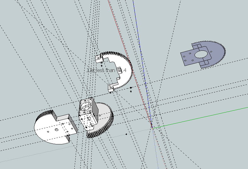
Quite a boring update, but the implications of what I can do with it are quite great. I've been toying with the idea for a while but since my main design tool is sketchup, there are no inbuilt tools for designing gears and so when I do it, I do it by manually designing and drawing out the teeth in sketchup and then rotating and copying them to make a full gear. There is a certain amount of intuition involved and it is by far not the best way to create mechanisms, but this one is working really well. What it does is gives me a really nice way to have a 'Yaw' inbetween the shoulder and elbow of my humanoid robot, but keeping the form factor within humanoid proportions.
![]() I have been putting this off for quite some time because I knew how long it would take me to get a working design.
I have been putting this off for quite some time because I knew how long it would take me to get a working design.What this also does, is gives me a really nice mechanism to use on a gripper, for a different project I have been working on in my head. A super cheap, but highly functional table top robot arm. The gear above is not really a 'bevel' since the gears are not angled and so don't truly mesh in the way a bevel does, but it does give me a really nice smooth motion between my cheap hobby motors and any Yaw joint that I want to make.
-
Kinematic Videos - Need Sensor Feedback and Big Feet
07/26/2017 at 23:20 • 6 commentsSo I did some further work towards controlling the legs. I added a set of sliders to the GUI that control the legs individually or together. The one for the left leg 'contracts' the leg so it raises up in a straight line. This is achieved by programming the slider to add values to multiple joints at the same time. Specifically, for every 1 degree that the hips and ankles move, the knee will move by 2 degrees. This is using very basic trigonometry and is the basis of inverse kinematics. I
Here is a poor quality vid of messy room and shakey legs. The slider controls the legs up and down movement. I should be able to use these movements at a later date to begin the basics of walking.
These next vids are demonstrating the use of one slider to teleoperate the legs. That one slider changes values on six joints at the same time. Previous movements have been generated by merging between two previously save positions, but those I need to teach it. The slider controlling all six joints is creating a new range off movements according to all possible configurations of an equalateral triangle made by the legs:
This video also demonstrates the PID program I have been working on to control the legs. I think the jerky motion is caused by the maths behind the PID I wrote. As I move the slider up, the difference is only small and so the leg power output is not high, but after a period of time, the error multiiplying over time causes the power to increase which makes the legs move upwards but they jerk upwards because they are catching up to the desired position. This would mean that I should slightly increase the effect of the Integral factor, so that the power increases slightly quicker. The danger however is that by increasing the speed that the integral affects the power output, the legs will become even jerkier . The legs will eventually have large LiPo batteries in the shins, this will prevent some of the wobble and jerk for two reasons. The batteries have enough current to drive the legs without cutting out ( the current power supply cuts out past 4 amps). Also having slightly heavier legs will lend overall stability to the structure. At the moment they are all motors and plastic, but not much weight which causes them to jerk and wobble. Having the extra weight will dampen the jerky motions a little.
The main change that is require however, is to completely redesign the feet. This will take a long time indeed. The feet need to be bigger ( not massive). They also need to have four rubber points to absorb shock but more importantly will house the force sensitive resistors to give feedback on weigh dispersion. I can then write a basic bit of code that modifies the foot position to always have the maximum weight dispersion. This will be the main ingredient that is going to stabilise these legs.
-
Pythagorus, Kinematics, Broken Hips, Angry Neighbours
07/25/2017 at 23:41 • 0 commentsSmall update. The last couple of nights I have been working on some new GUI sliders for the legs. The idea was to create a slider that would make one of the legs raise up at the hip and knee. I created three sliders one for each leg and one which controls both legs at the same time.
I got reacquainted with Pythagoras and worked out that if trying to keep the hips and ankles level with each other they should contract by an equal amount( of degrees) whilst the knee needs to contract by double the amount(of degrees).
In theory I should be able to keep the legs upright whilst cycling up and down a crouch manually with the slider rather than merging between saved moves.
In it's most basic form, this is the essence of kinematics. Although there is much more work to be done on making and accurate mathematical model of the legs.
This gives me a very basic ability to control the total 'crouch' by moving one slider up and down. By alternating crouch on each leg I can begin to build the rudiments of a walking gait. Although the hips need much more strengthening before they will rigid enough to do this properly.
The below video shows me using the slider to control all 6 joints at the same time:
I thought it would be fun to throw some extra difficulty into the mix by putting it on carpet to see how it would fare.
When the legs cut out completely this is due to the power supply I am using. It only provides max 4 amps at 12 volts so the legs sometimes try to draw much more, usually at an extreme crouch.
I am designing bigger, more rigid feet for it, that will also feature quad pressure sensing to enable autonomous balancing to stabilise the legs.
-
PID woes Solved and New designing phase
07/22/2017 at 12:33 • 0 commentsSmall update 22/07/17:
I realised something that had been working against me massively. The legs seemed to be much less controlled than I expected, always shakey and the power wasn't as high as I had thought it should be.It all came down to the PID calculations I had programmed. I was racking my brains to trying to work out how to calculate the Derivative value and then I noticed something. I had been adding my P and I values together because the sum fitted nicely into a usuable value for PWM. But with PID you are supposed to multiply the P and the I and this gives you the proportional output required. However when multiplying my P and I , I was getting crazy values, far too high to use with PWM. The solution was really simple - divide the result by 10!
The I have values I can use in PWM and I can also tune that number to vary my overall speed and strength. The legs seem to move a lot more smoothly now.
I am currently trying to design the upper arms. It is surprisingly difficult to work out because I need to add a 'swivel' to the section between the shoulder and the elbow, which allows the arm to move in a similar manner to humans. I have some designs for turntable type swivel motion but they are not rigid and they are also enormous which is not going to translate very well to a human type form.
I have also printed a 'bicep' joint which I am fairly happy with, but it impossible to know how it will look until I design the upper arm . This part is always really difficult because I know how I want to achieve something and have a rough idea of how to do it, but it takes a huge amount of time to work the 'best' way to do something. It means sketching on paper or even just staring at pieces that I have laying around and trying to reconfigure them in my mind to get a working piece. Very long and quite frustrating.
![]()
As you can see. My designs are nothing more than massive cogs. No where near as advanced as the harmonic drives and brushless motors of ASIMO or those massive robotis servos. But to get a similarly sized robot servo I would be looking at a huge cost, whereas I can make each joint for around £5 so if it means I can make a whole robot I am going to go with the simple and cheaper option. The way I see it, human muscles are very much analog. The thing that makes ballet dancers so graceful is a combination of the sensors and processor. If you have a good processor and lots of sensor data, you can achieve a decent amount. I was always planning to put a powerful onboard PC solution on the machine, so that should be able to crunch the numbers. The arduino is essentially just a big servo controller.
-
Motor Control and Rigidity Frustation
07/21/2017 at 18:26 • 0 commentsSo I wasn't able to get it stand on one leg reliably enough to do it in a sequence without me holding it up. I don't want to ever rely on harnesses and having people nervously standing behind it.
There are a number of factors that need to be overcome. The problem is, they are all boring. So I designed the biceps instead.
Problem 1:
I keep getting oscillating of the limbs around the set point. This is because I wrote a PI control of the motors on the arduino myself and I'm no engineer/mathematician. I got it to move and couldn't be bothered to continue programming preferring instead to make it do funny moves.
What I really need is the D (ok stop sniggering, I didn't mean that).
I have a variable for the distance between where the joint is and where I want it to be, this is in very basic terms the Proportional. Then I have a variable for the amount of time that the distance is far(so the error over time, which accumulates) and that is the Integral part.
I worked out today how I am going to do the Derivative part but it is difficult to keep the concept in my mind. I need a variable which tracks the rate at which the error increases or decreases. It needs to know when to expect the error will be zero again so it can lower the power before that happens. So to get the rate at which the error increases or decreases.....(even now I am struggling to visualise how to do this in an ardunio loop) .
The difference between the set point and the current position is called diff[x] in my loop and it is calculated for all joints. If it is a negative number I convert it to a positive (I reverse the number again when applying the power). So if you were to look at a list of the differences over a number of 10 millisecond cycles it might look like this:
millis() diff[30]
millis()+10 diff[15]
millis()+10 diff[7]
millis()+10 diff[1]
So the above would represent a joint position accelerating to the correct set point. So I need to track the rate of acceleration or deceleration ( not of speed but of rate at which the error changes). Then my code would need to increase or decrease the power depending on rate. I also need the code to know if it is accelerating or decelerating. Well I am going to have a think about this now (maybe a tiny crying session). Then come back and try to solve this. All I know is that it will involve maths which I am rubbish at.
I was going to write about all the problems but that will get boring so I will just summarise the next one:
Problem 2:
The waist/hips rotators are mounted inside their 'bearings' too losely so the whole frame is unstable, which is not good for standing on one leg. I tried to be too clever with the design and should have stuck to directly mounting on skateboard bearing like I do with everything else. I won't have time now to redesign the whole hips/waist so I am going to print a load of add on pieces that will stabilise these joints enough.
-
Programming Control in Processing
07/20/2017 at 10:22 • 0 commentsSo I have taken a few days off work and I am going to make good use of them to really get some groundwork programming done to start automating movements on this machine. I am also going to start thinking about the 'spine' and upper body. Ideally I would design one piece of the upper body first so that I can leave that printing and then work on the programming but designing a whole upper body is a daunting task and requires a lot of thought.
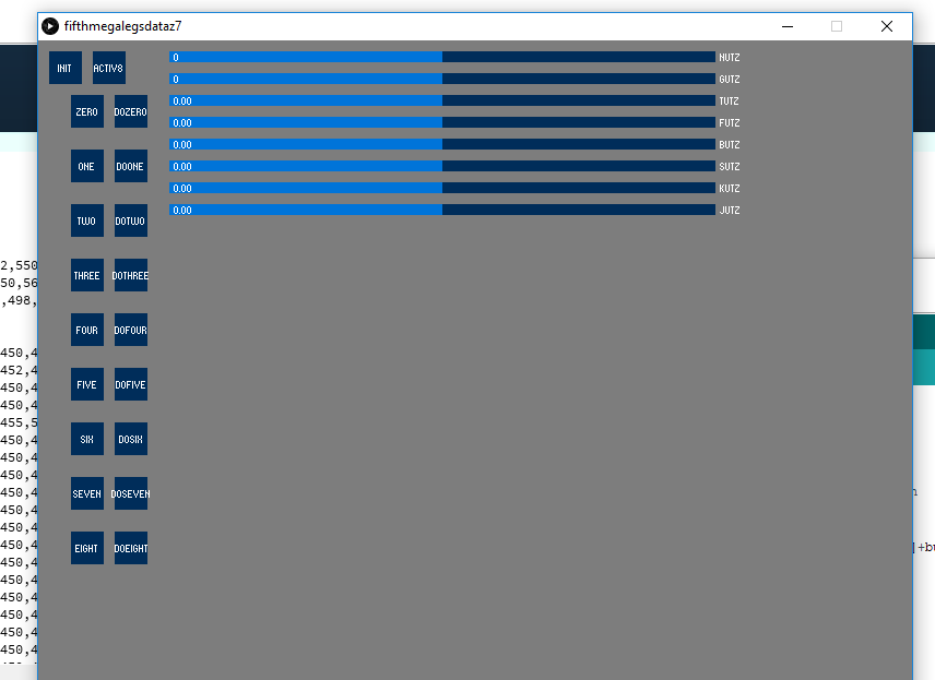
Here is a snapshot of my current GUI in Processing:
![]()
It's very basic as I am still learning processing. The buttons on the left save the positions to the memory as integer values. The buttons directly next to them that are called 'do -xxx' are the ones that recall the positions that I have saved.
Last night I programmed two additional buttons, the first is labelled 'init' which stops power to the motors. This is needed in case the legs freak out, but is more useful when positioning the legs to save down a new position to the memory. The the 'Activ8' button enables the power to the leg motors again.
The sliders are programmed to add a value to more than one joint so I can control multiple joints with one slider. This enables me to lean the legs to the left or right. The hips and ankles will all move by the same angle to make it lean.
I am using 'controlP5' library to create the buttons and sliders as it seemed to have good documentation and lots of tutorials on youtube. The GUI is in it's infancy. Today I will aim to program a position sequencer that uses the millis() function to playback a set of preprogrammed positions. The big space you can see on the GUI is were the sequencer willl go. The goal is to get it to shift it's weight to one side and then lift one leg without falling over. If I can do this then it should be able to walk. The problem is, I have been programming loads in visual basic and this is making things confusing with the c++ of Processing. They are very similar languages but it's the syntax that is making me struggle.
Inexpensive 3D Printed Full Size Humanoid Robot
I'm designing a super cheap humanoid robot platform. It is going to be the same size as an adult person.
 I have been putting this off for quite some time because I knew how long it would take me to get a working design.