 Sebastian Goscik
-
1Laser cutting
The chassis can be laser cut from 3 materials each with their own pro's and con's:
- Acrylic - Looks good and is affordable but extremely brittle and easy to break.
- Plywood - Cheap, strong and can easily be modified but some people think it looks less attractive.
- Polycarbonate - More expensive than acrylic but not brittle.
I personally would recommend using plywood as it is more robust and can easily be hacked by students wanting to modify their robots.
If you do not have access to a laser cutter there are several companies who offer laser cutting services for very reasonable prices online. I have included a ready made file for Razorlab. The design fits onto their P1 size sheets and will set you back ~£11.50 for a plywood E.R.N.I.E, although I am sure in bulk the price would decrease. Be sure to use 3mm thick material
-
2PCB Manufacture
I highly recommend getting professionally manufactured PCBs from one of the many Chinese PCB fab houses. I used Elecrow and got 50 boards produced for £22.57 (45p a board!). If you would like to recreate the exact boards I got made you can simply visit this page and enter the following settings:
- Layer - 2
- PCB Thickness - 1.6mm
- Copper Weight - 1oz 35um
- PCB Size - 10cm Max * 10cm Max
- PCB Color - Black
- Suface Finish - Hasl (lead free)
- PCB Stencil - NO Stencil
- Panelizing - 2-5 copies
- Lead time - Shipped in 4 to 7 days
The zip file you need to attach can be found here
-
3Wheel Prep
Each kit needs 3 wheels, two of which need to have their hub enlarged to 5mm. This can be done very easily on a drill press running on a slow speed or by hand with a drill bit.
-
4Assembly Step 1
Solder stranded wire onto the motors. The wires should be around 20cm long. If in doubt, cut the wire longer, you can always cut it down later.
-
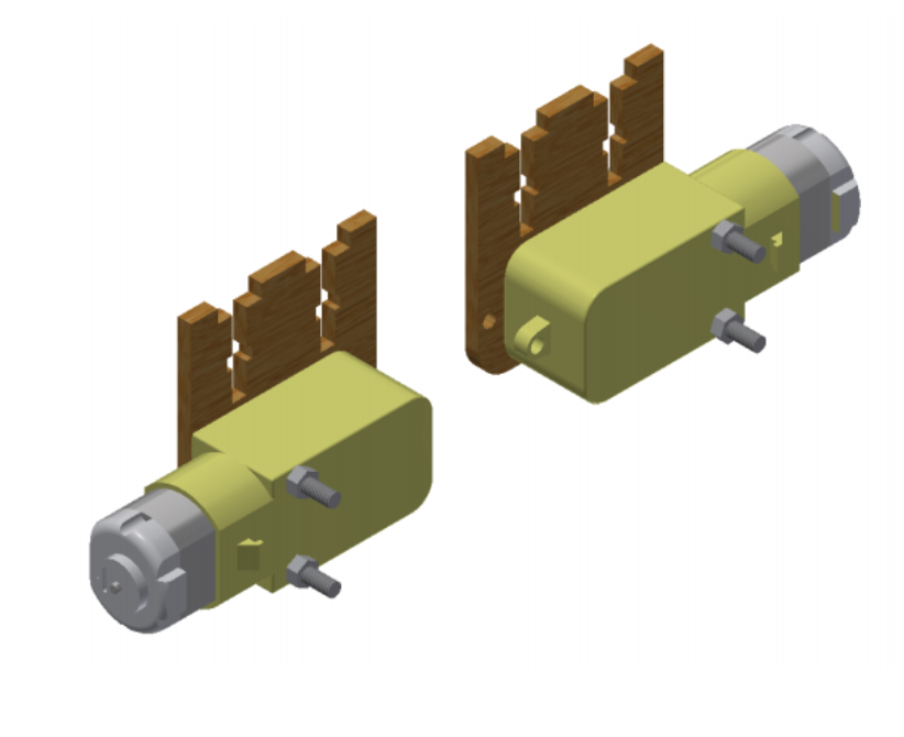
5Assembly Step 2
Attach the motor to the mount using the (longer) 30mm screws:
![]()
Repeat this for the second motor but this time mirrored. The end result should look like this:
![]()
-
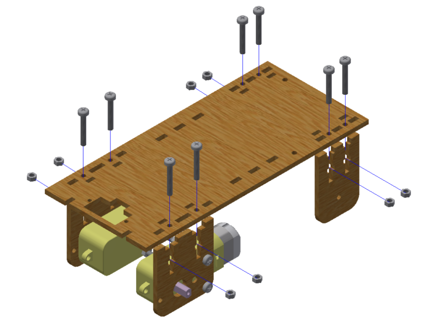
6Assembly Step 3
Attach the motor and axle mounts to the base plate using the 20mm screws:
![]()
NOTE: Do not over tighten the screws if using acrylic. Acrylic is a very brittle plastic and will crack easily if too much force is applied. Do not worry if the mounts have a little bit of movement in them, this will not affect the robot’s functionality.
-
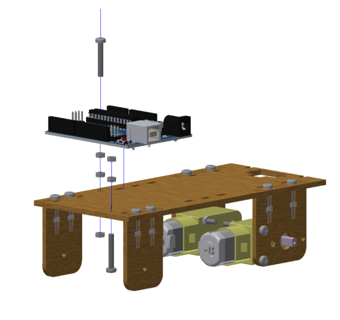
7Assembly Step 4
Mount the Arduino to the base plate using 2 nuts as a spacer. Note that the front screw goes from the bottom and the back screw from the top:
![]()
-
8Assembly Step 5
Apply electrical tape around the rear wheel (the one with the smaller hole). This is so that the back wheel can easily slide around when the robot turns.
-
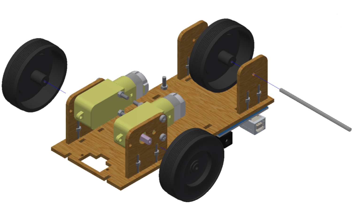
9Assembly Step 6
Attach the wheels to the robot:
![]()
-
10Assembly Step 7
You will find that the rear axle easily slips out of its mounts. To fix this simply wrap a little bit of electrical tape around the axle so it cannot slide around.
E.R.N.I.E
A cheap to produce and easy to assemble robot for use in STEM education.

Discussions
Become a Hackaday.io Member
Create an account to leave a comment. Already have an account? Log In.