-
Sharing the List of Tracked Planes
08/26/2014 at 05:48 • 0 commentsJust some updates on my attempt to share the list of tracked planes on flightradar24.com. In the earlier post 'Ttracking Your Very First Planes' I indicated that I was not successful in doing so. The output from the ADSB receiver was processed by ADSB#. Despite pointing ADSB# and fr24feed (flightradar24.com's feeder software), fr24feed still reports the '"Too few aircraft, at least 2 required" error, despite seeing like 5 aircrafts being tracking in adsbscope. What was interesting then was that fr24feed indicated that the basestation was 'OK'. Normally if there is any configuration problem, fr24feed will spit out a big fat 'ERROR' message at the 'Basestation' entry.
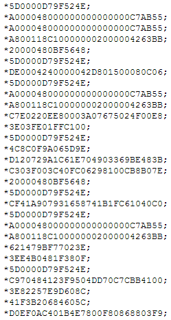
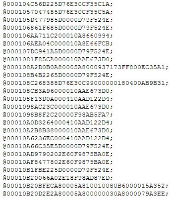
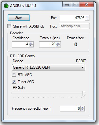
I looked up more on this issue and found the cause, I think. The data format output by ADSB# is simply just incompatible with what fr24feed requires. Here is a screen shot of the dump from ADSB# on port 47806 -
![]()
It turns out the 'correct' software I should use is rtl1090 which was superseded by dump1090, so I went with that. dump1090 can be downloaded from - http://www.satsignal.eu/software/dump1090-win.1.08.2705.14.zip
A good guide for setting this up can be found at - http://planeplotter.pbworks.com/w/page/79995023/Dump1090
Since my ADSB receiver driver is working and I did not install rtl1090 previously, I only need to unzip the downloaded folder and run 'dump1090.bat'. You should see something like this -
![]()
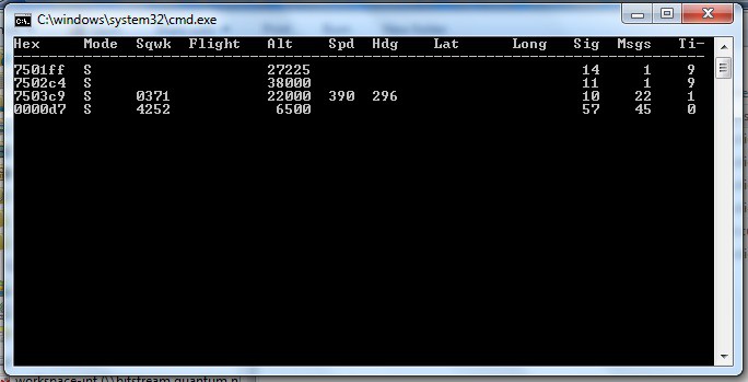
The screen shot of the dump from dump1090 on port 30002 is completely different -
![]()
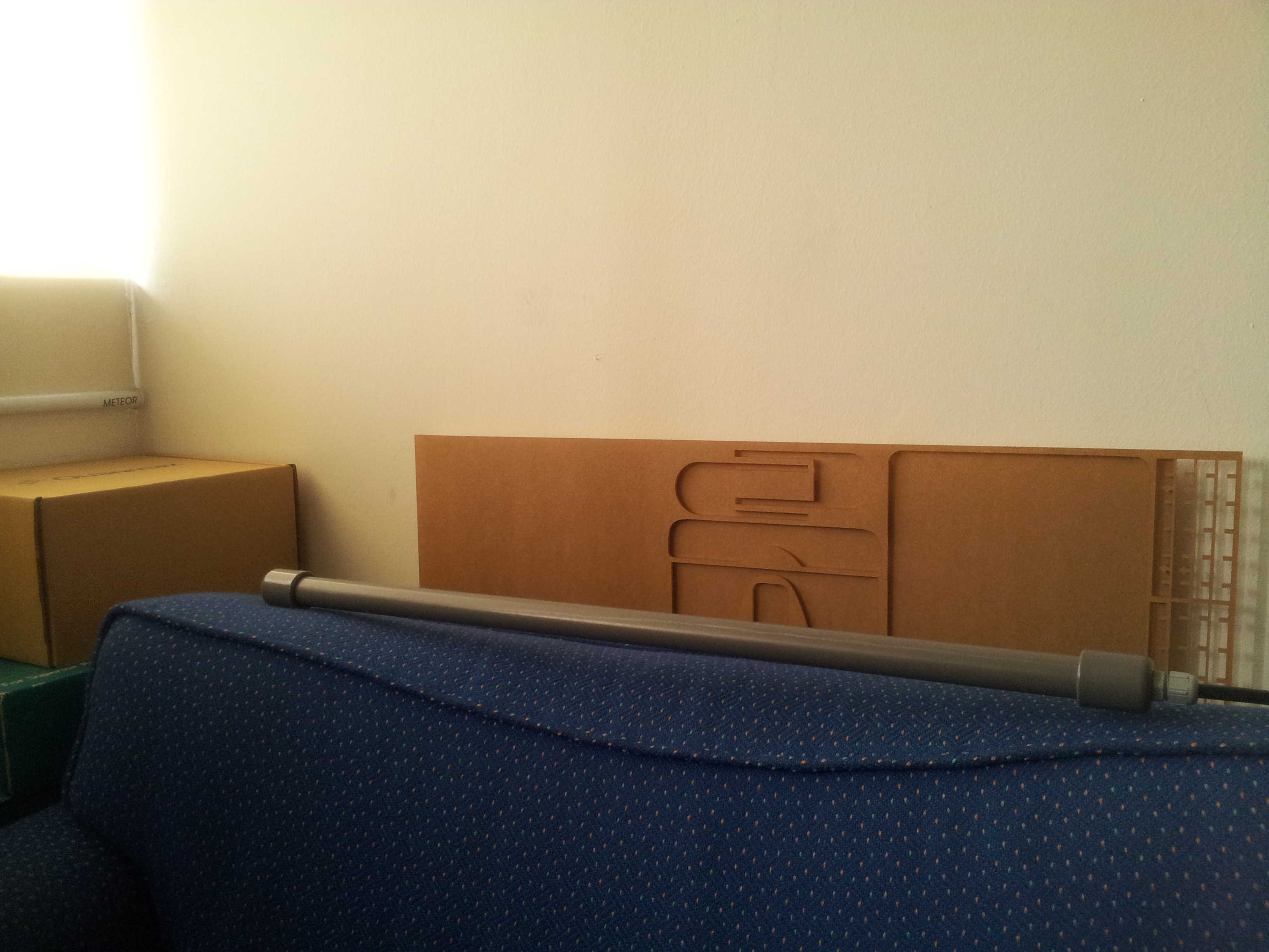
I then went through the routine of entering my email and approximate GPS coordinates and started fr24feed. It again return with a 'Basestation:OK' and 'Too few aircraft, at least 2 required ' status. First I have to say I am testing all these in my office. Soon I realized that my antenna is lying horizontally on a sofa below the window ledge level -
![]()
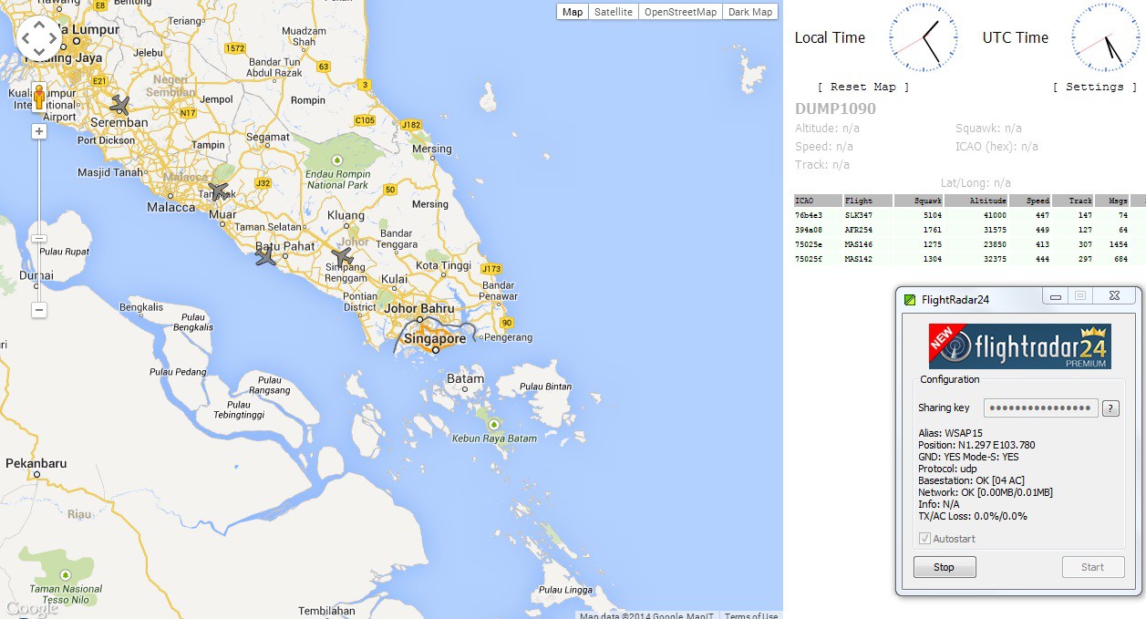
Of course in doing so the signal is in the wrong polarization with respect to the antenna. The antenna probably cannot see any portion of the sky when placed below the window ledge. I took the antenna up and held it in my hand. The number of tracked planes short up to 5 and fr24feed managed to generate a sharing key and off I go (fr24feed at lower right corner) -
![]()
The dump1090 software also has a web based output accessible by browsing the local ip address on port 8080 (shown above).
After that to obtain the premium membership (non of those timeout nonsense) on flightradar24, I just created an account with the same email and click the 'I am feeding data' option.
I noticed that not all the planes that was tracked by my receiver are visible on the flighradar24.com website. Conversely when I put down the antenna (no I was not holding the antenna up all the time when I was doing this) so that no planes were tracked on my receiver, non of those tracks on flightradar24.com are dropped. Maybe their server requires the same track from a number of feeds before it accepts it as a genuine track? This means a lone platform with a single receiver in the ocean may not work. Will check more on this. Meanwhile onwards with the sharing.
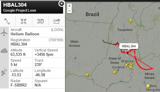
Another interesting thing I found while scanning around on flightradar24 map is this -
![]()
The two balloons on the map turns out to be balloons launched by Google for project loon - http://www.google.com/loon/. It is a project by Google to essentially strap wifi repeaters (or something like it) on balloons and with a large fleet of these balloons, try to bring internet to every corner of the earth (hemmm...).
What is interesting is that the balloons forms a ring around some latitude of the earth in the southern hemisphere which is determined by the jet streams in the stratosphere. These jet stream crosses the oceans. Could this be part of the solution to the communication problem with the Global Seer platforms in the ocean? Cliffhanger here I guess.
-
Harnessing the Power of the Sun
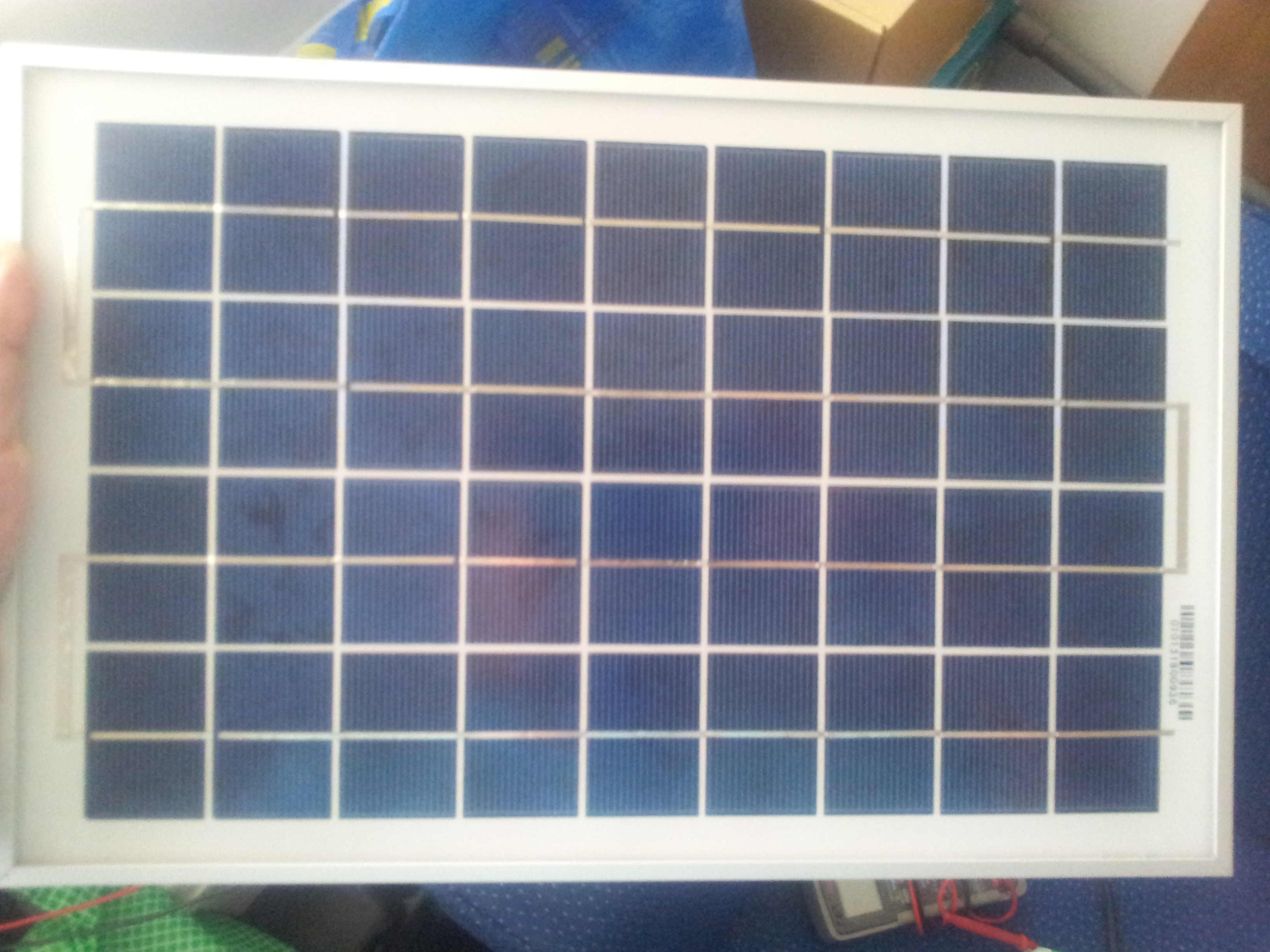
08/21/2014 at 03:17 • 0 commentsFinally I gotten around to wire up the 10W solar panel (shown below) I have laying around. I will probably get myself some higher wattage panel in the future. For the moment this should be sufficient for the land-based receiver. One thing I noticed when shopping for solar panel is that I was told by most, that these panels are extremely durable outdoor, unless something drop smack onto them. For marine usage, I have my doubts. Will need to look more into this. There are also flexible panels. Maybe they will prove to be useful.
![]()
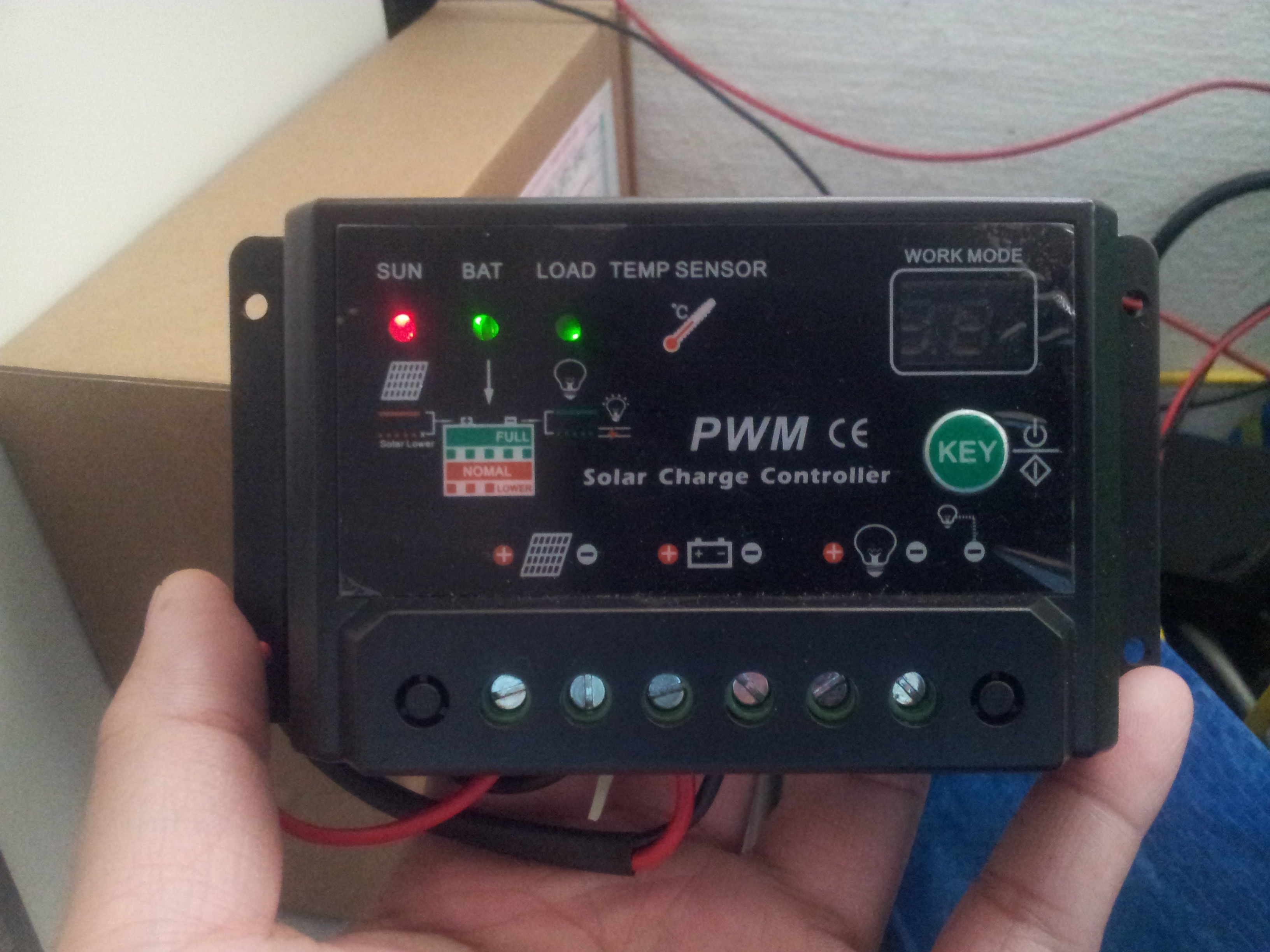
A solar panel alone is not really useful with the output voltage changing and all with sunrise and sunset. What is needed is a charge controller. A charge controller just regulate the output voltage for the purpose of charging a battery and powering a device when the sun is up. The load then draws the power from either the panel or the battery depending on the amount of sunshine. I went out and got myself a, 'one hung low' (hemm expression sounds familiar), 30A charge controller (shown below). The charge controller has a 'key' button to switch between a few modes. Basically this particular controller is meant for lighting purposes. It turns off the load (lights) when the sun is up and turns on the load for a set number of hours after the sunlight diminishes. These modes are EXTREMELY bad for the ocean platform as you may imagine. So I switched to a mode that continuously power the load. After I set it to the permanently powered mode, I disconnected the panel and battery. Fortunately the controller does retains the setting if it is completely powered down.
![]()
I wired the panel and a 12V SLA battery to the controller and commenced testing. More on this in the upcoming project log.
-
Tracking Your Very First Plane
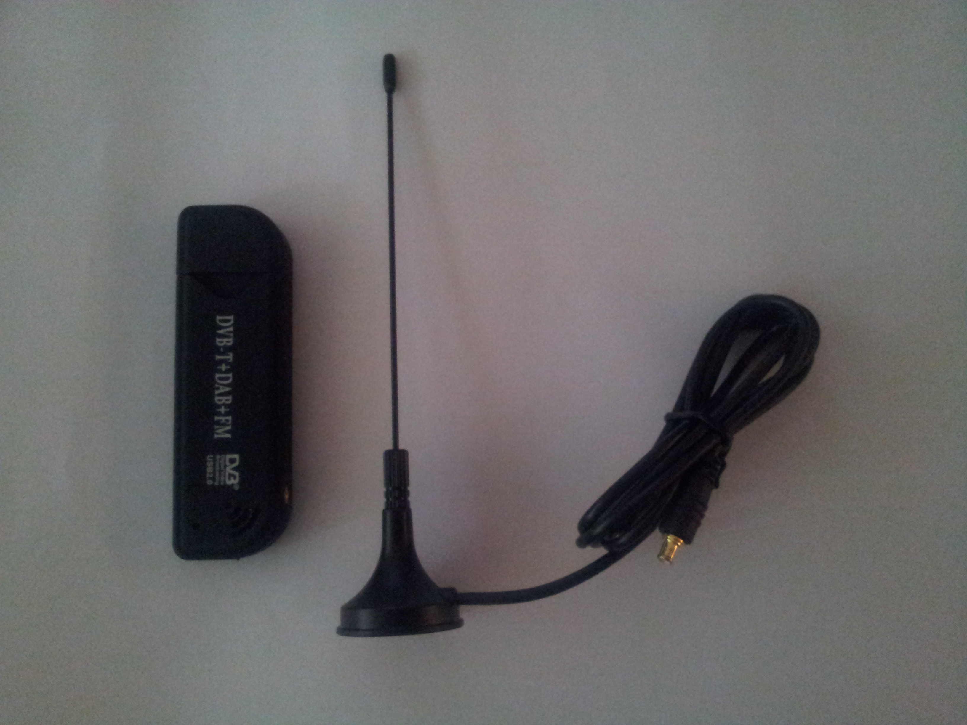
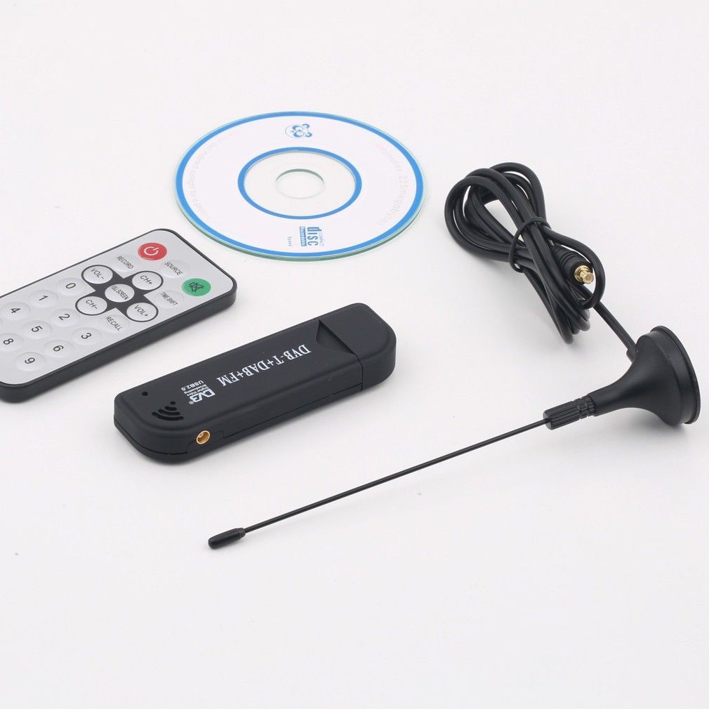
08/21/2014 at 02:38 • 0 commentsMy USB digital tv tuner (Shown below, DVB-T Realtek RTL2832U Elonics R820T 50MHz - 2200MHz RTL-SDR) a.k.a ADSB receiver finally arrived in the mail. Got it from ebay from a seller based in Hong Kong for about 10USD. But took more than three weeks to arrive. Should have bought like a dozen. Anyway this project log entry documents the installation and my first test of the receiver using Window based software. Will port it over to a Raspberry Pi running some distro of Linux (not sure which one yet) in the near future.
![]()
A very comprehensive guide for the process is avaliable at - http://www.flightradar24.com/dvbt-stick
Basically install the driver from the tiny cdrom included with the receiver. Plug in the receiver so that the driver takes hold. Use the software Zadig from - http://sourceforge.net/projects/libwdi/files/zadig/zadig_v2.0.1.160.7z/download
to replace the stock driver for Windows 7.
Now here is where I departed from the instruction from flightradar24.com. I downloaded the files from - http://sdrsharp.com/
and unzipped them into a folder. Go into the folder 'sdrsharp' and launch the program 'ADSBSharp.exe'. ADSBSharp.exe is sort the software back end that interfaces with the receiver and then pipe the result via a TCP port. You should see something like this -
![]()
I left the 'Port' setting at its default value of 47806. Next time if there are multiple ADSB server running, this port setting can be changed. Click start to start crunching plane information. Next I downloaded the software 'adsbscope' from - http://www.sprut.de/electronic/pic/projekte/adsb/adsb_all.zip
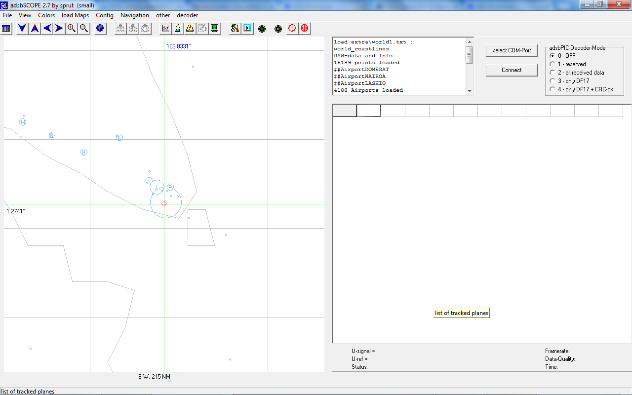
Once again unzip all the files into a folder. Launch 'adsbscope27_256.exe' in the folder 'adsb_all\pc_software\adsbscope\27\' This is what you should see next.
![]()
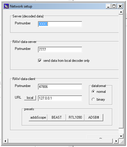
As this is not the first time I am running this, I have reset the software's default receiver location. You can do the same by centering your receiver location on the map and choosing 'set Receiver Location' from the 'Navigation' menu. Once that is done select 'save default' from the 'File' menu. Now go menu 'other' -> 'Network' -> 'Network setup', click on the 'ADSB#' and 'local' button. You should see this -
![]()
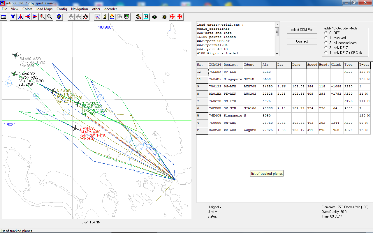
Now go menu 'other' -> 'Network' -> 'Raw-data Client Active' and start tracking airplanes. After I connected up my homemade antenna and played around with some of display settings, this is what I saw -
![]()
Surprising I can see any planes at all sat in my office waving around a 60cm PVC pipe.
Some other tests I did yield unexpected result. I brought the receiver to the roof top a few days later but actually detected less planes. Maybe I just happen to hit timing with minimal air traffic? I also tried to share the receiver output on flightradar24 using their fr24feed software, but gotten a 'too few aircraft' error despite plenty are displayed on adsbscope. Will cover more on these tests in future log once I figure out where is the problem.
-
The Ear of the Global Seer?
08/20/2014 at 19:36 • 0 commentsI think many would have guessed correctly that is a project log entry on the construction of an ADSB antenna. The digital tv tuner (shown below) a.k.a the ADSB receiver in the component list comes with a dinky little wire antenna with a MCX jack (more details on the tuner coming up in future blog). For antenna, bigger (up a certain length) is better, at least for this case.
![]()
An excellent guide for making your own ADSB antenna can be found here - http://www.balarad.net/
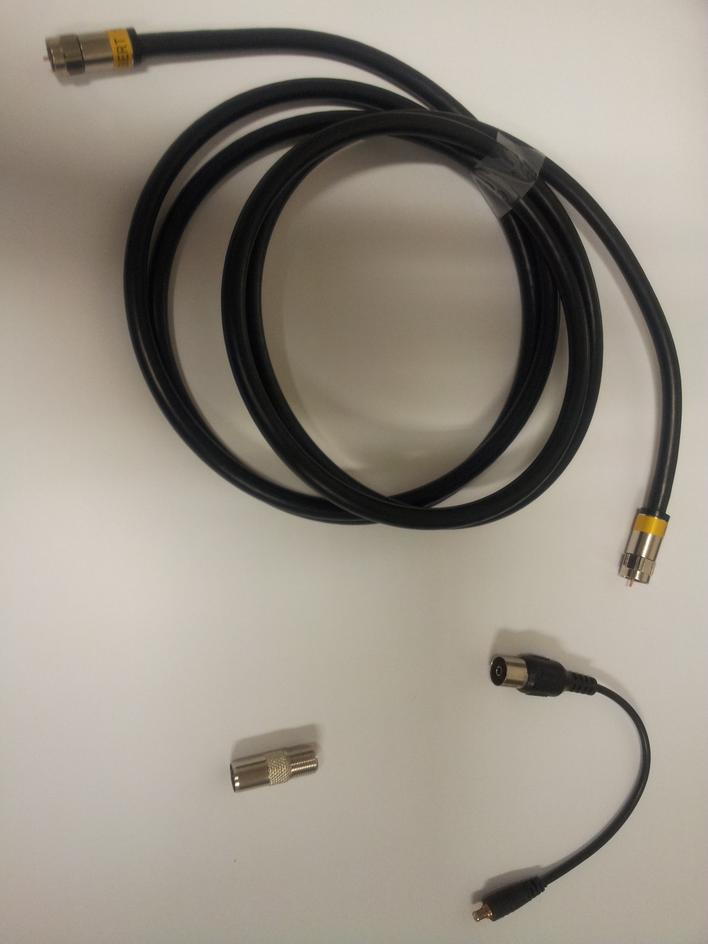
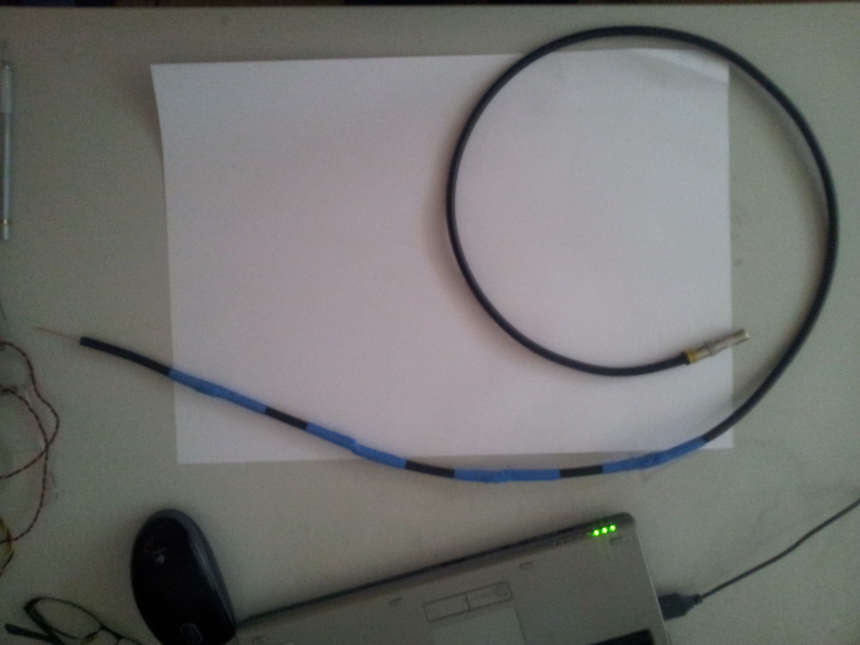
What I am actually building is called a Coaxial Collinear Antenna. The parts needed is a length (2m for my case) of 75Ohm, RG-6U coaxial cable (shown below, left)
![]()
Firstly I need to calculate what is the actual length each of the segments that I need to cut from the coaxial cable. The segments need to be half the wavelength of the received signal. Let's start from the fact that the ADSB signal is broadcasted on a frequency of 1090Mhz. So the wavelength is given by
wavelength = c/frequency where c = 299792458 m/s (this is exact) is the speed of light in vacuum.
Substituting a frequency of 1090Mhz in the above formula, we get the wavelength to be 0.275m. Thus half the wavelength will be 0.138m. Now this value of 0.138m is only applicable for the case for a radio signal traveling in vacuum. In an dielectric medium like in a coaxial cable, radio signal travels slower. This is a similar effect as in refraction as light travels slower in glass. Since the frequency remains unchanged, the wavelength must also decrease. From the datasheet of the cable, the 'Nominal Velocity of Propagation' is listed as 83%. Thus the magical length to cut the coax cable to 0.138 X 83% giving me 0.114m.
Now the next question is how many segment do I need? Ideally, the greater the number of segments, the more sensitive the antenna pickup is. Above a certain number of segments, the losses in the cable dominates and one no longer sees an increase in sensitivity. I believe in Hak5 they went for a 16 segment antenna here -
http://www.youtube.com/watch?v=zMoKs1eiyO4
For me the choice of the number of segments to use is based on a more mundane consideration. The antenna is supposed to be mounted on an ocean platform. So I would say antenna length of about 60cm is acceptable. Thus I went with a four segment antenna as a test.
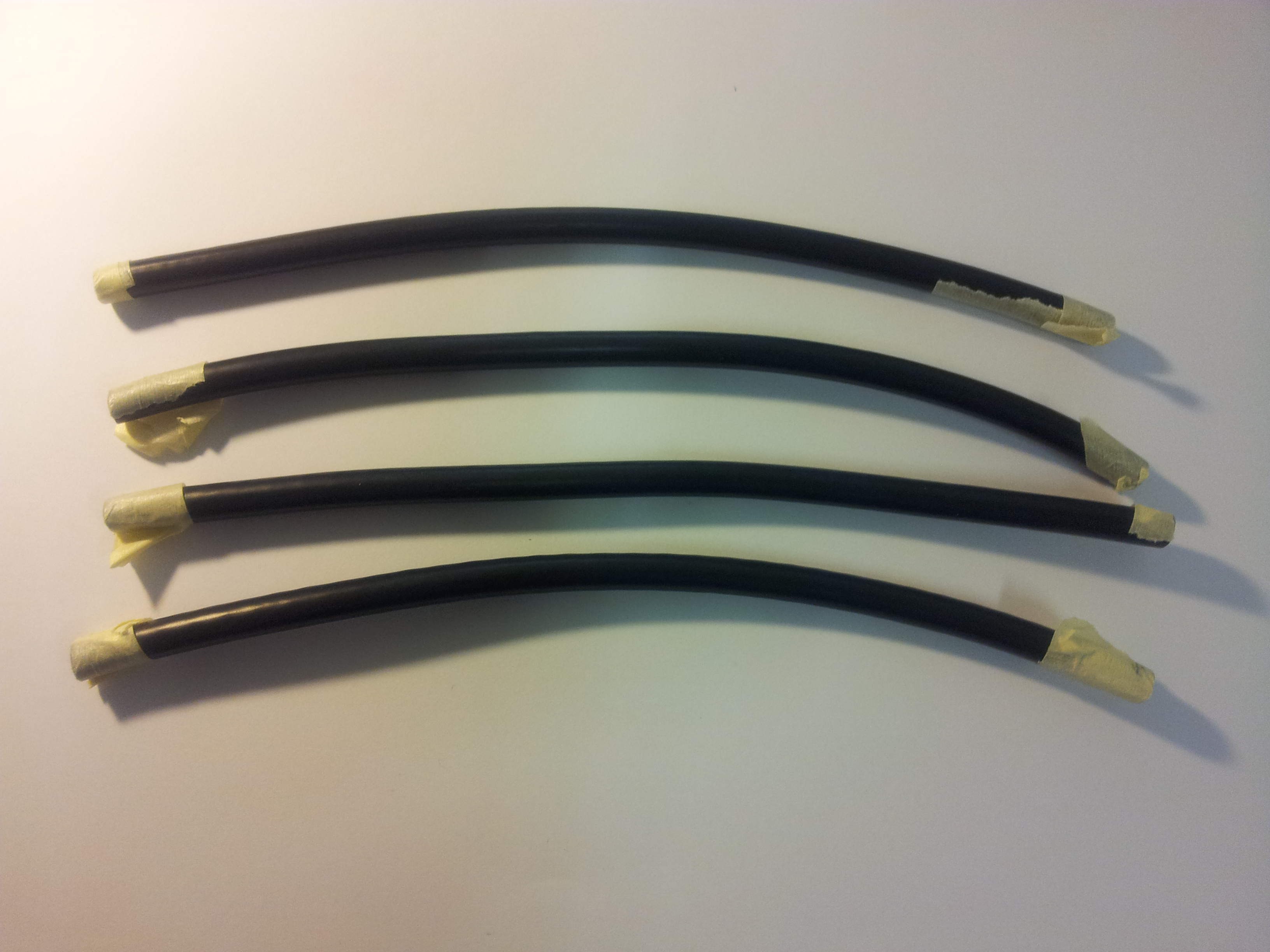
The antenna is assembled by inserting the core of one cable into the sleeve of the other. According to the balarad website, it is recommended to leave 5cm of the core uncut. With that consideration the length of each of the segment I need is 0.114 + 0.05 + 0.05 = 0.214m. With this number and my trusty vernier caliper, I commenced cutting. I have use marking tape on the cable to mark the places I need to cut. Result of this exercise is shown below.
![]()
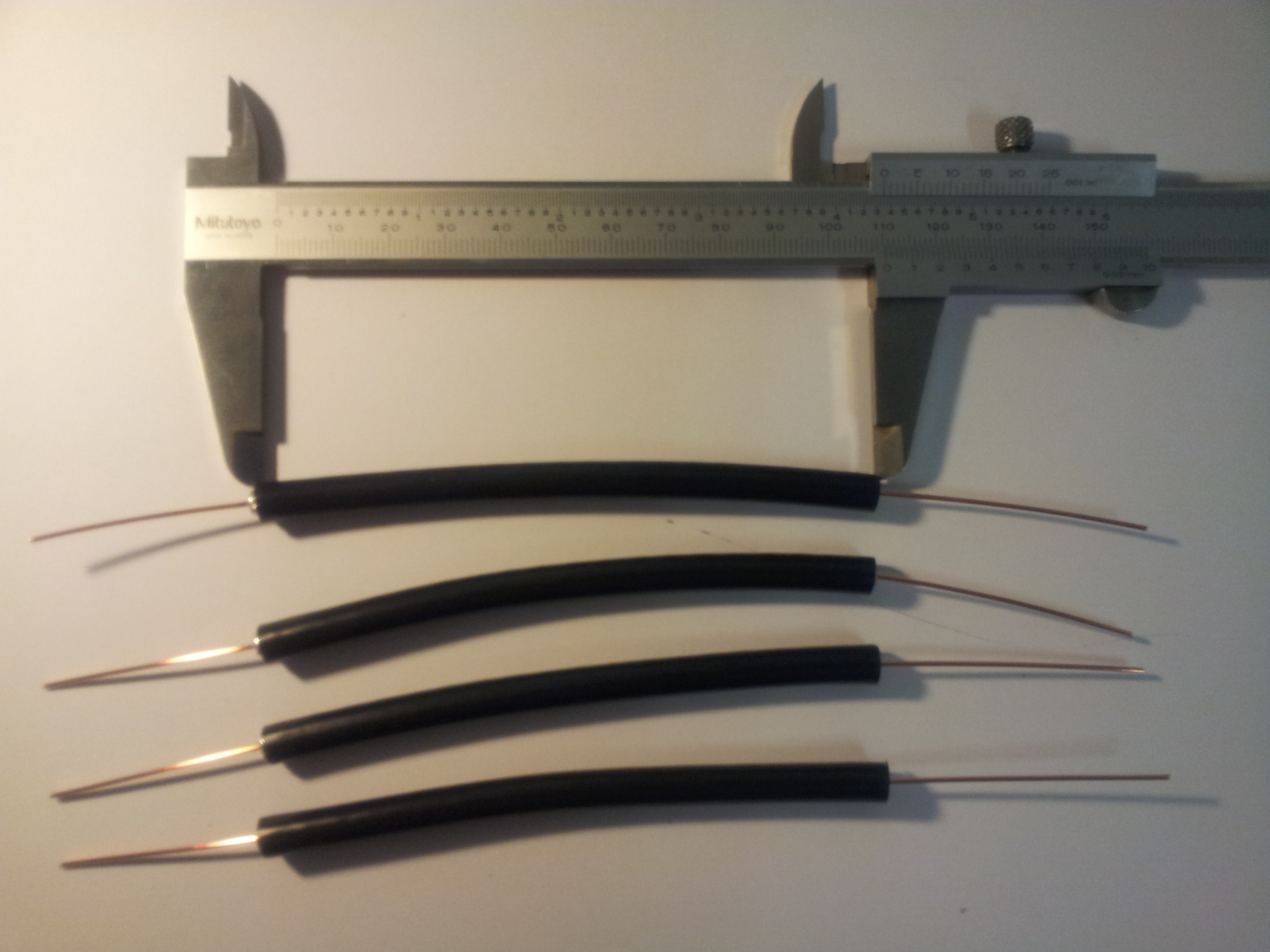
I then stripped off 5cm of the outer layer leaving only the central core (shown below).
![]()
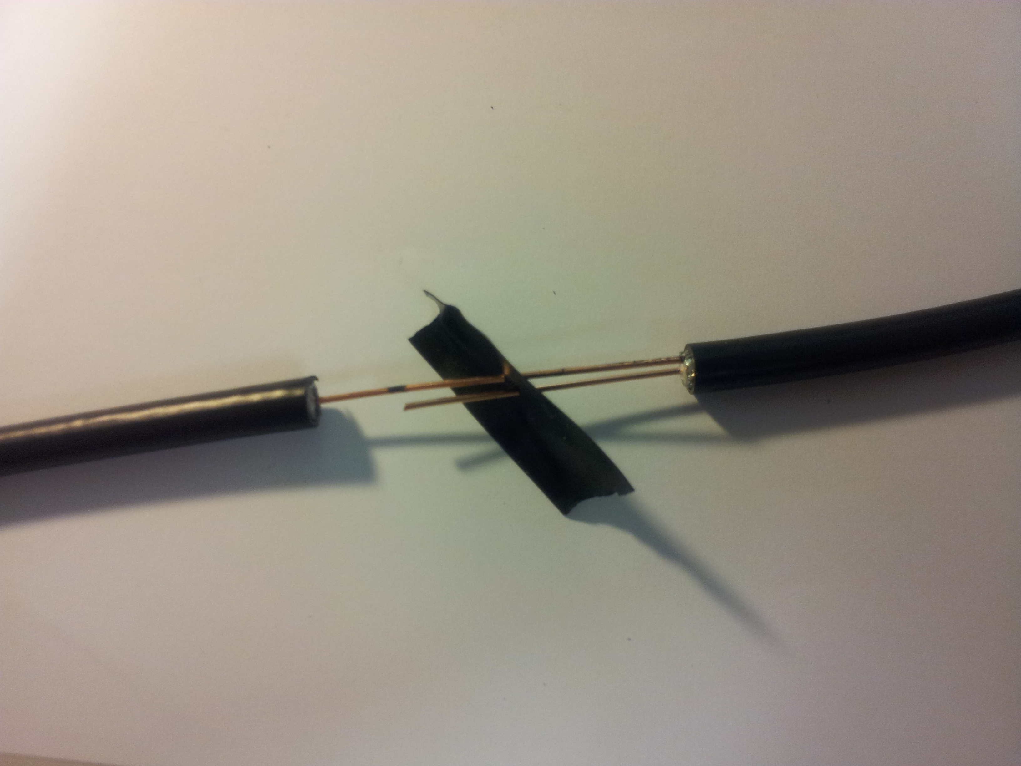
The core of each segment is then inserted into the sleeve of the other with electrical tape for insulation (shown below). The cables are then taped together with electrical tape.
![]()
It seems that the recommended 5cm length for the exposed core is probably too long. The core have a tendency of perforating the sleeve of the other cable. So I would say a 2.5cm length for the exposed core would probably be sufficient. It is prudent to do a continuity check after every segment is installed. For every even number of segments, check for continuity between the core and sleeve on the opposite ends. For odd number of segments, check between the cores on the opposite ends and similarly for the sleeves. At one end of the cable I spliced in a patch of coax with the connector. With an application of heat shrink tubing, here is the final result.
![]()
However when I tried to characterize the frequency response of the antenna using a spectrum analyzer in the lab, I got an almost flat response. I strongly suspect that the connection between the tv coaxial connector and the BNC of the analyzer is bad (I was just hold them together with my hands). Will test cover more of this in the future. For the moment will test with the actual receiver I guess.
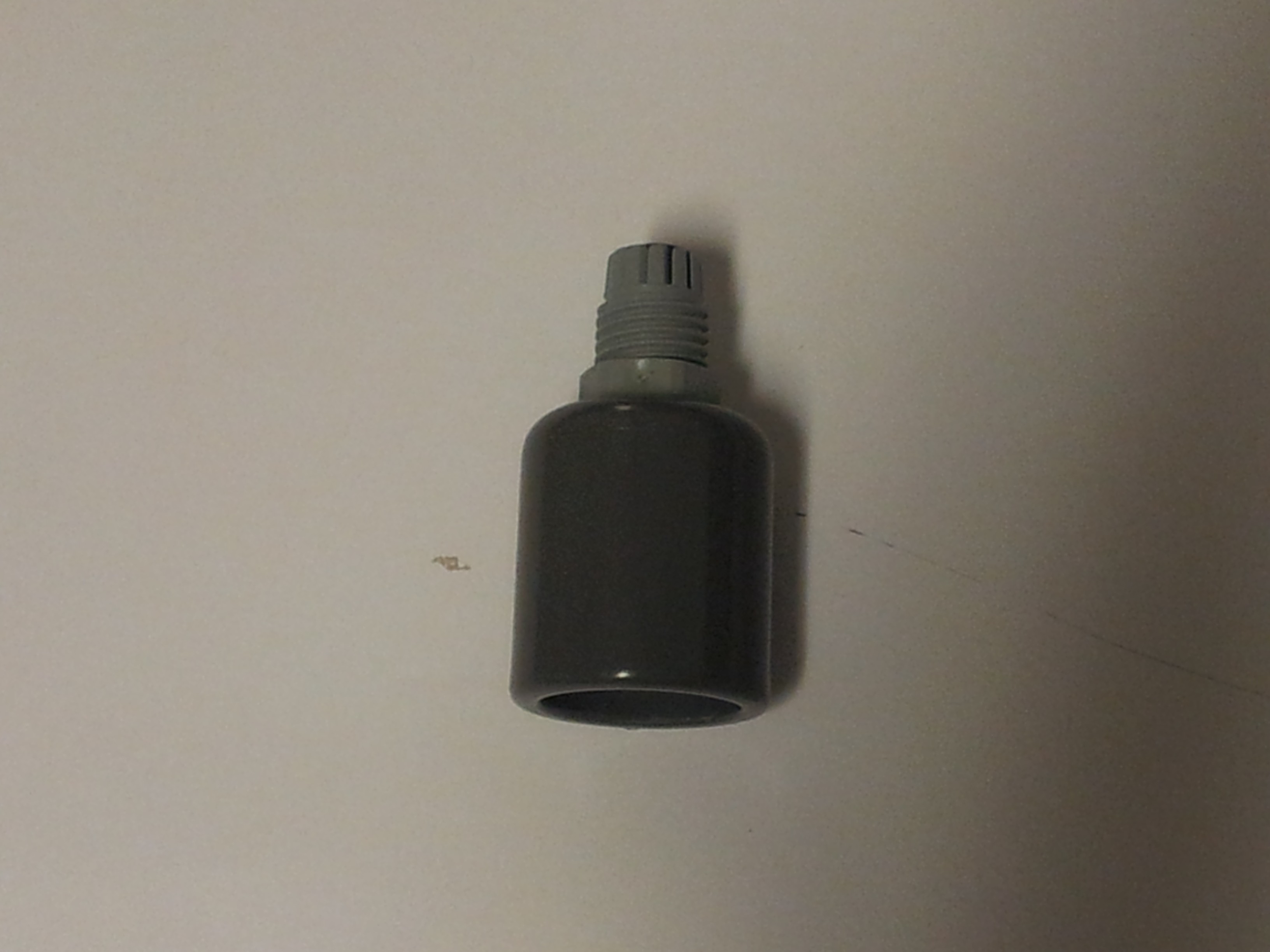
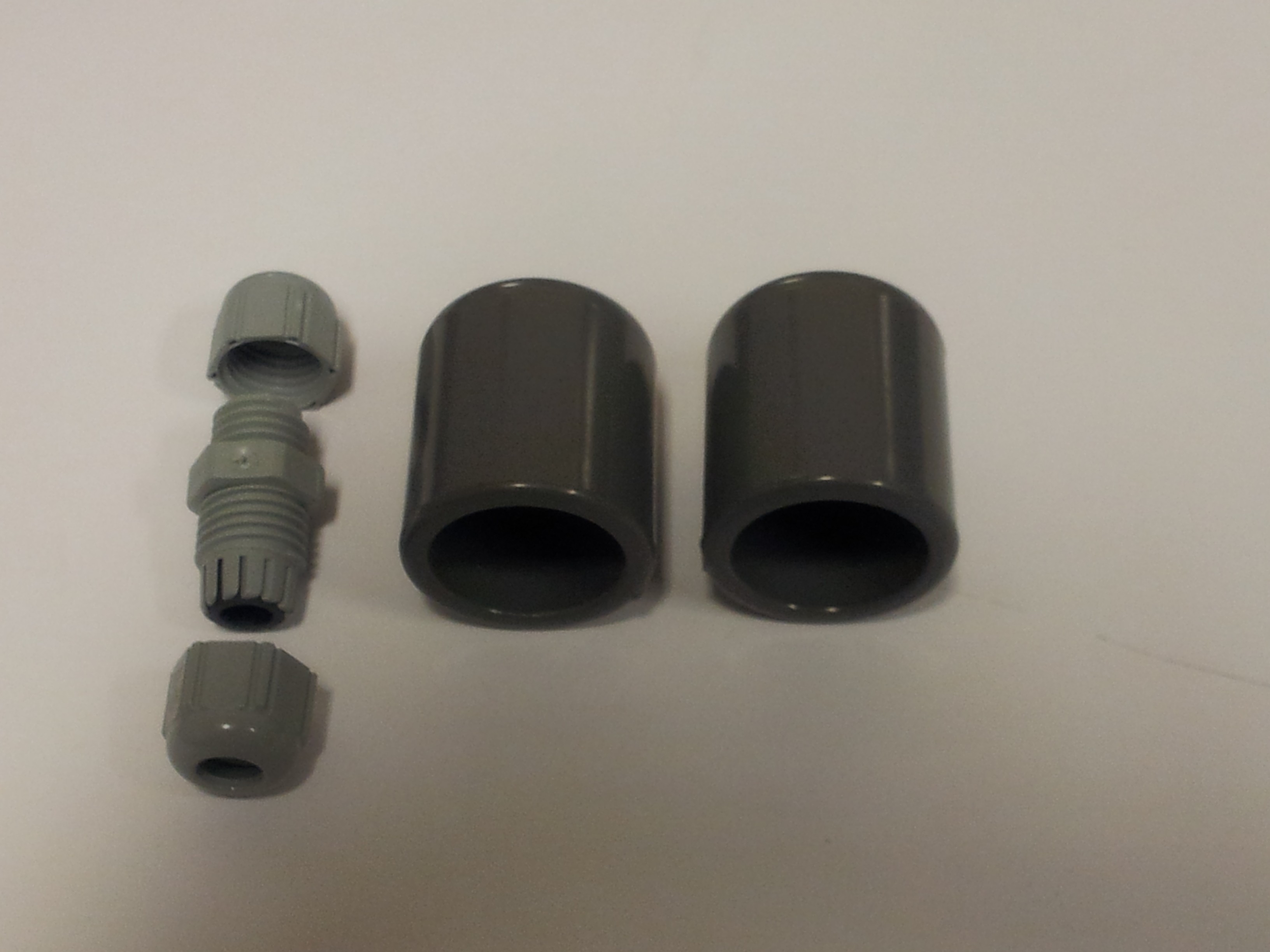
Next step is to put the antenna into a 16mm inner diameter PVC pipe for support. For that I also need two end caps (shown below, right) for the pipe and something call a M12 X 1.5 cable gland (shown below, left).
![]() The cable gland gives a water proof feed through for a cable through a panel. I then drilled a hole in one of the end cap for the cable gland (shown below). Was too pedantic about get the hole exactly centered so went ahead and used a lathe instead.
The cable gland gives a water proof feed through for a cable through a panel. I then drilled a hole in one of the end cap for the cable gland (shown below). Was too pedantic about get the hole exactly centered so went ahead and used a lathe instead. ![]()
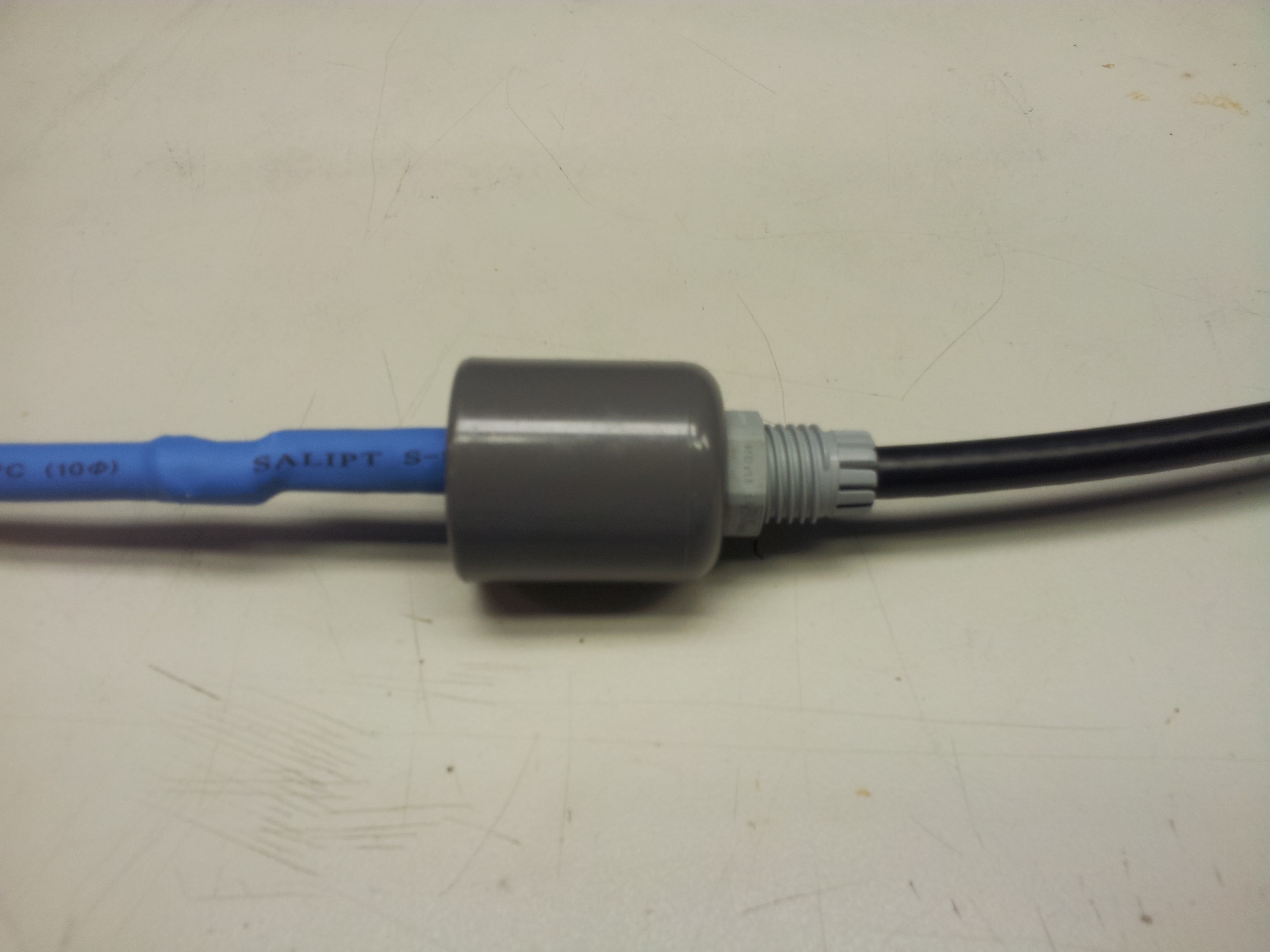
I then PVC glued the cable gland into the end cap (shown below). The end cap is simply too thick to use the accompany nut for the cable gland.
![]()
Here is when I realized I have made a mistake. With the antenna assembled, it is too big to be inserted through the cable gland. So I need to remove the last section of the antenna, thread it through the cable gland. The result is this -
![]()
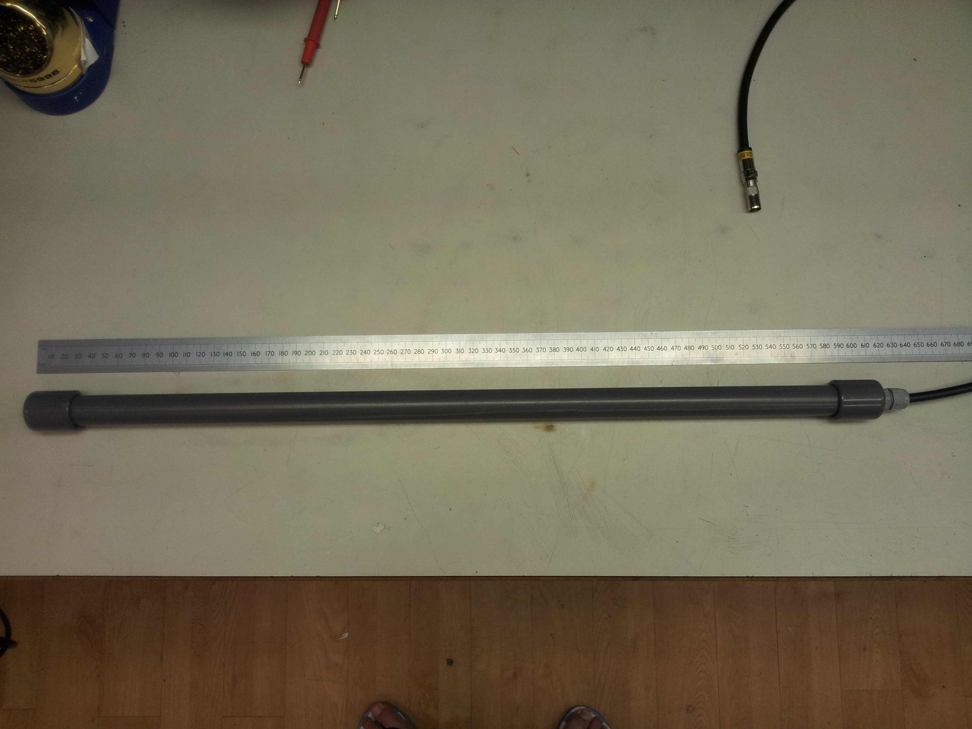
I then cut a length of PVC pipe approximately 60cm long, PVC glued on the end cap at the end without the cable. The other end with the cable I just press fitted it. Probably need to remove it in the future for some modification. Here is the finished product -
![]()
-
The Three Step Road Map
08/20/2014 at 18:54 • 0 commentsAfter giving it literately a few minutes thought, given the scale of the build it will probably be useful to set up some incremental/intermediate build goals that will lead to the final build. Conceivably, in this way, various sections can be tested individually and much needed experience in dealing with each subsystem can be gained. With that, here is the three step road map/build goals -
1. Build a solar powered land based ADSB receiver station. The receiver station should be completely off the power grid and have GPS capability. ADSB information received will be shared on flightradar24.com firstly via wifi then 3G/4G network. I will list the component needed (or rather what I have) in the component list.
2. Build a solar powered sea based ADSB receiver station on board of a floating bouy near the coast. This will add on to the previous build and is where the satellite/shortwave communication comes in. Hope I can pick up some skill in making 'marine-grade' fiberglass hull here.
3. The final goal, build the Global Seer Platform. By this stage all the ADSB components should be fairly well understood. The main task will be to build the autonomous ocean-faring platform.
-
Conceptualisation
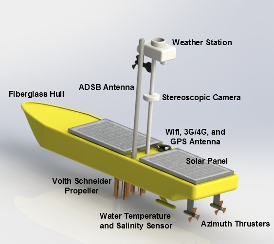
08/20/2014 at 04:59 • 0 commentsThe is the first entry in the Global Seer project log. Before I get into the nitty gritty of any actual build I will always engage in bouts of blue-sky thinking about the project in question. For this case, they resulted in 'approximate' platform design in the cover photo (shown again below but with legends this time round). Although it probably will not resemble the final iteration in any shape or form, this flight-of-fancy design does allows me to have an overall view project and points to a direction to head towards...
![]()
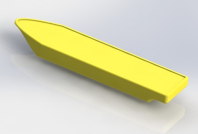
The first target of my blue-sky thinking is the design of the ocean platform. I guess what is needed here is a platform that is compact/streamlined (so that it can braves the storm with relative ease?) and have a relatively large payload capacity. Speed in this case, though preferable, is not really required in this case. From the way I see it, a Global Seer platform will probably be undergoing a long range trek to the destination. Once at the destination, it will only be required to make short distance positional changes to improve coverage. Therefore I went with a rather conventional single hull design (show below) for the platform. As it stands now, the hull from bow to stern has a length of about 1.3m and a width of 308mm. This is largely determined by the size of the sample solar panel that I have got which is 390mm X 254mm . From the deck to the keel is about 150mm. This is determined by the height of the sealed lead acid batteries. More studies will need to be conduced to find out the actual water displacement of the hull, address stability issues and carry out refinement of the keel design.
![]()
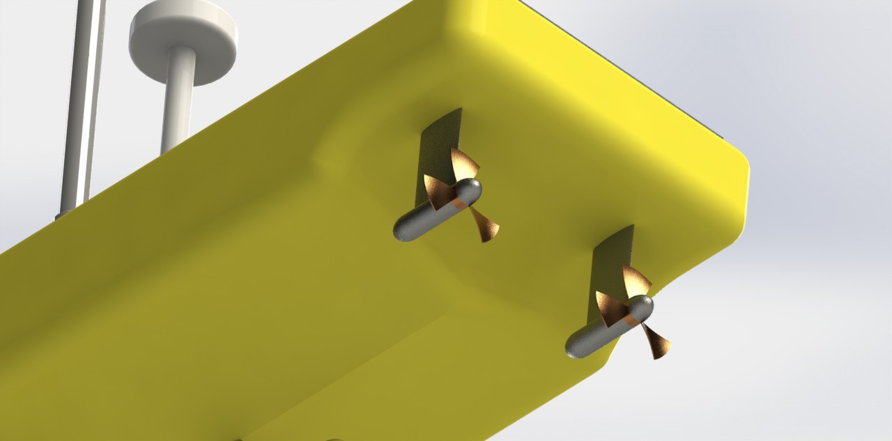
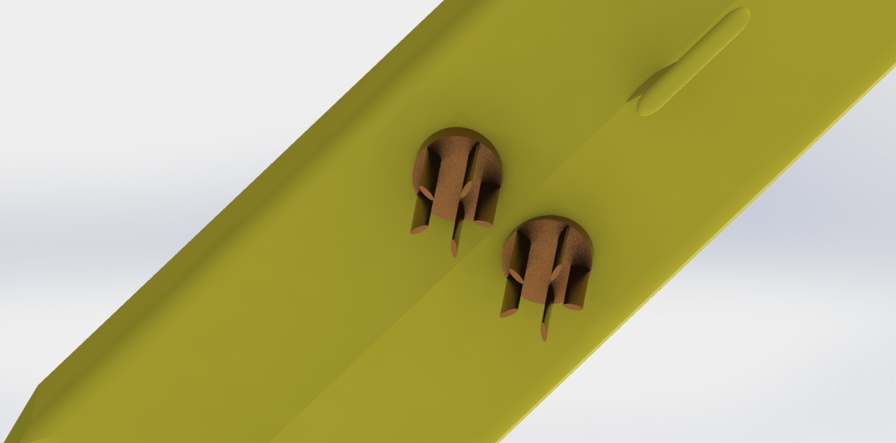
The next choice issue that I will tackle is the selection of a propulsion system. For this case I have opted for use of pair of azimuth thrusters (shown below) as oppose to the traditional rudder system. These are basically motor and propeller pair attached to a swiveling mount. This arrangement is supposed to be more efficient compared to inboard mounted motors as torque lost through a long drive shaft is eliminated. There is increased maneuverability as the thrust can be directed in any direction even in reverse. As the motors are outboard, there is also more space in the hull for various payloads. Two thrusters instead of one for redundancy consideration. Mechanically it is also simpler as the number of rotational coupling through the hull is reduced from 4 to 2. The only case when I cannot think of a clear advantage over a normal rudder is what happens when the swivel mount fails? There may also be issue in the design of the rotational coupling through the hull as there is a need to feed power to the motors.
![]()
Another problem that is related to the propulsion system is the issue of position holding/station keeping. Strictly speaking the area coverage of the ADSB signal does not require high accuracy position holding to effect. Even for the purpose of multilateration (MLAT), the determination of the position of an aircraft from the minute time delay (referenced with GPS clock signal) between signal received from it at different receivers, is dependent mostly on the accuracy of the GPS (typical about 10m). However if the Global Seer platforms are placed in a mesh network for communication relay the issue of position holding becomes important. In order to bridge a certain communication distance with as little number of platform as possible, it would be helpful to place the platform just within radio communication range of each other thus requiring highly accurate position hold.
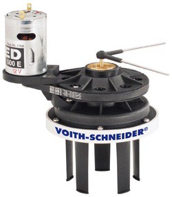
While the azimuth thrusters excel in providing excellent maneuverability, they are very slow to react to fast positional drift. This is because in order to redirect the thrust, the whole azimuth assembly needs to be rotated. While trying to source for a solution to this problem, I stumbled upon a propeller configuration that I think is very ingenious. It is called the Voith-Schneider propeller. A rc version of it is shown below.
![]()
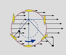
Basically it consists of a series of blades that are mounted vertically beneath a ship. The pitch of the blades are determined by a series of mechanical linkage to the central rotating shaft. The mechanical linkage is implemented such that water is always directed in a certain direction (shown below the direction of force acting on the blade by the water). Depending on the relative position of the of the mechanical linkages and the rotation shaft, water can be redirected in any direction almost instantly. A video animation of its workings can be found here (http://www.voith.com/en/products-services/power-transmission/voith-schneider-propeller-10002.html).
![]()
What I have planned is to implement this at the keel near the amidship (shown below). I will try to come up with a design that locks all the blades in the forward direction during long distance straight line sailing such that the blades act as stabilizers. Once at the destination, the blades will be unlocked for position holding.
![]()
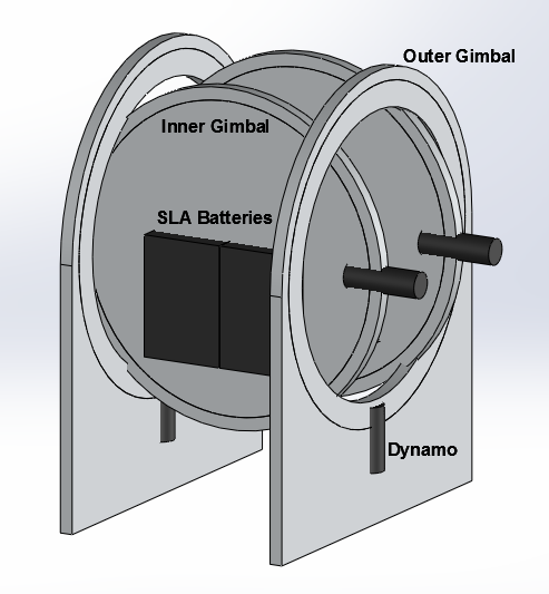
The last of my blue-sky thinking have to deal with the power systems. On the vast expanse of the ocean, two things are in abundance - sunshine and waves. The solar panel kind of address the problem of extracting energy from sunshine. What about the waves? Surely the pitching and rowing motion of the platform can be tapped for energy. An idea (shown below) popped into my head. The heaviest component the sealed lead acid (SLA) battery can be mounted in free moving gimbals. Because the battery are mounted off center in the inner gimbal, it will always settle in a direction point downwards. This movement can be used to drive dynamos to augment the power generated by the solar panels. One possible issue is that the whole contraption takes up a lot of space. More design work needs to be done here I suppose.
![]()
The Global Seer
A project aimed at developing a reconfigurable sea-based relay network for ADS-B out signal for aircraft tracking over the oceans.
 The cable gland gives a water proof feed through for a cable through a panel. I then drilled a hole in one of the end cap for the cable gland (shown below). Was too pedantic about get the hole exactly centered so went ahead and used a lathe instead.