-
Update #11 quick update on new image and case version
09/20/2018 at 20:53 • 0 commentsDisc image
There is a new version of the PiPod image available right here, this version has a few improvements:
- Quicker boot time ~30sec thanks to disabling the network
- It's easier to copy music to the device
- The updating of the software is easier
- Using your own Python launcher is made easier
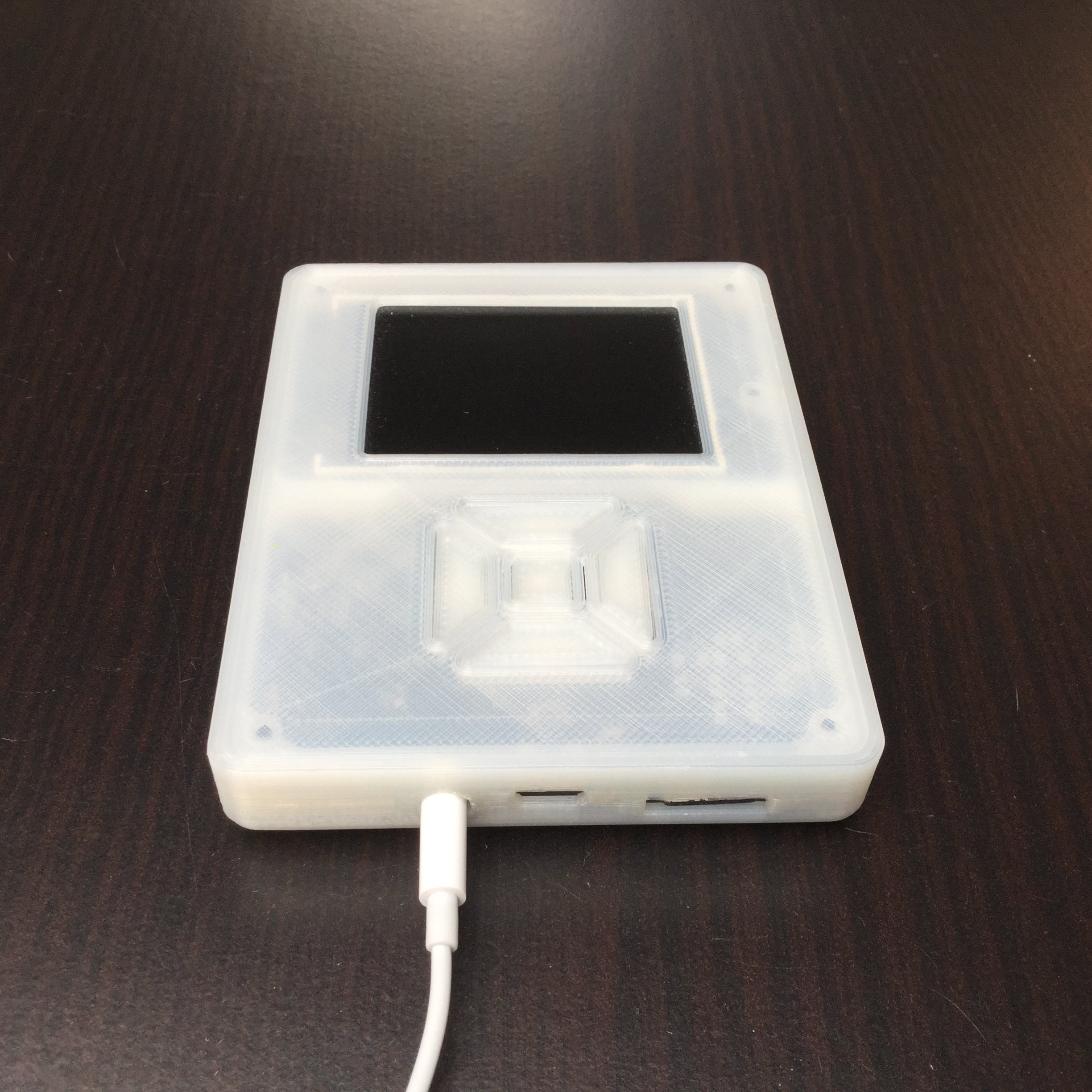
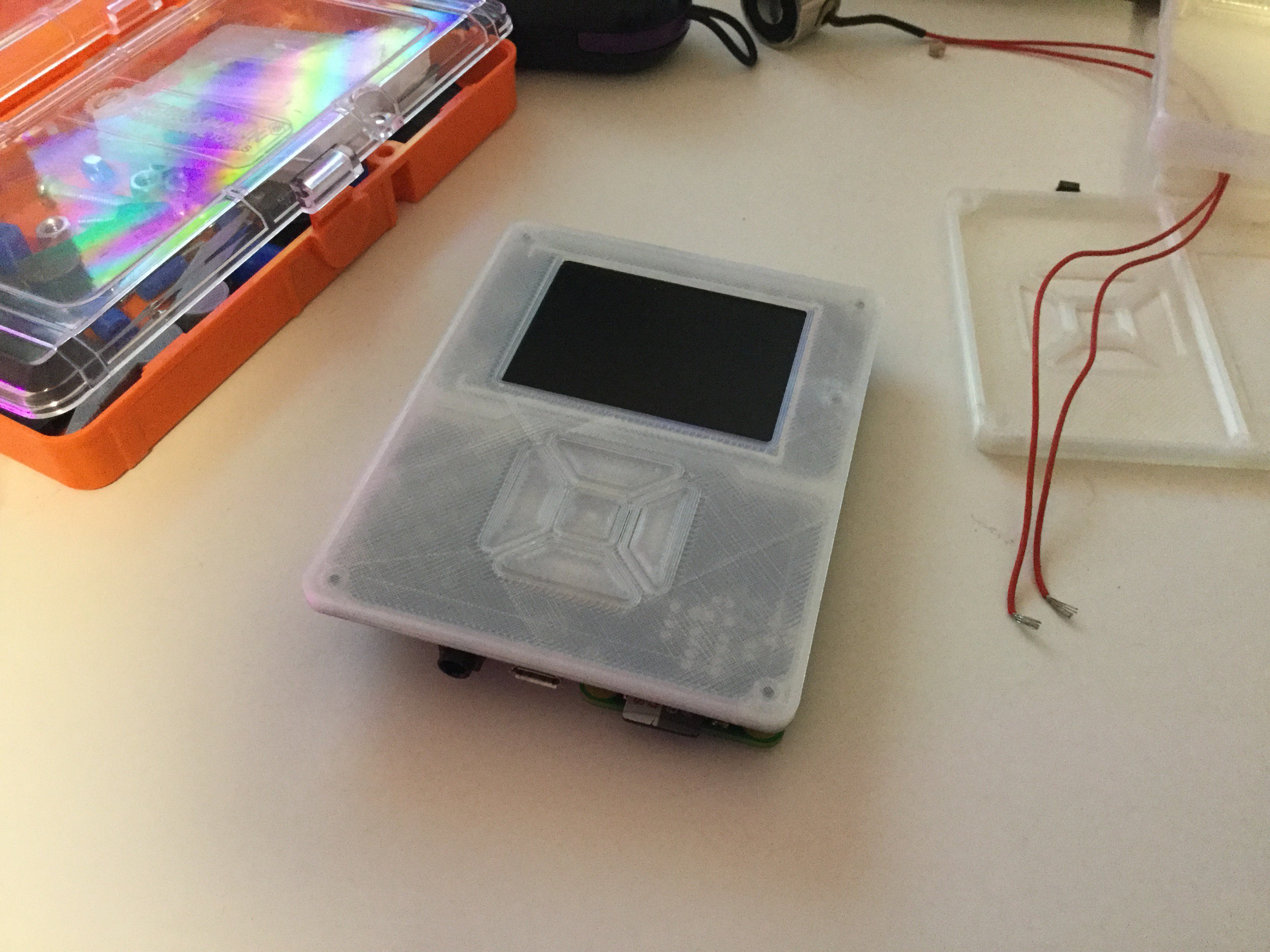
New case files
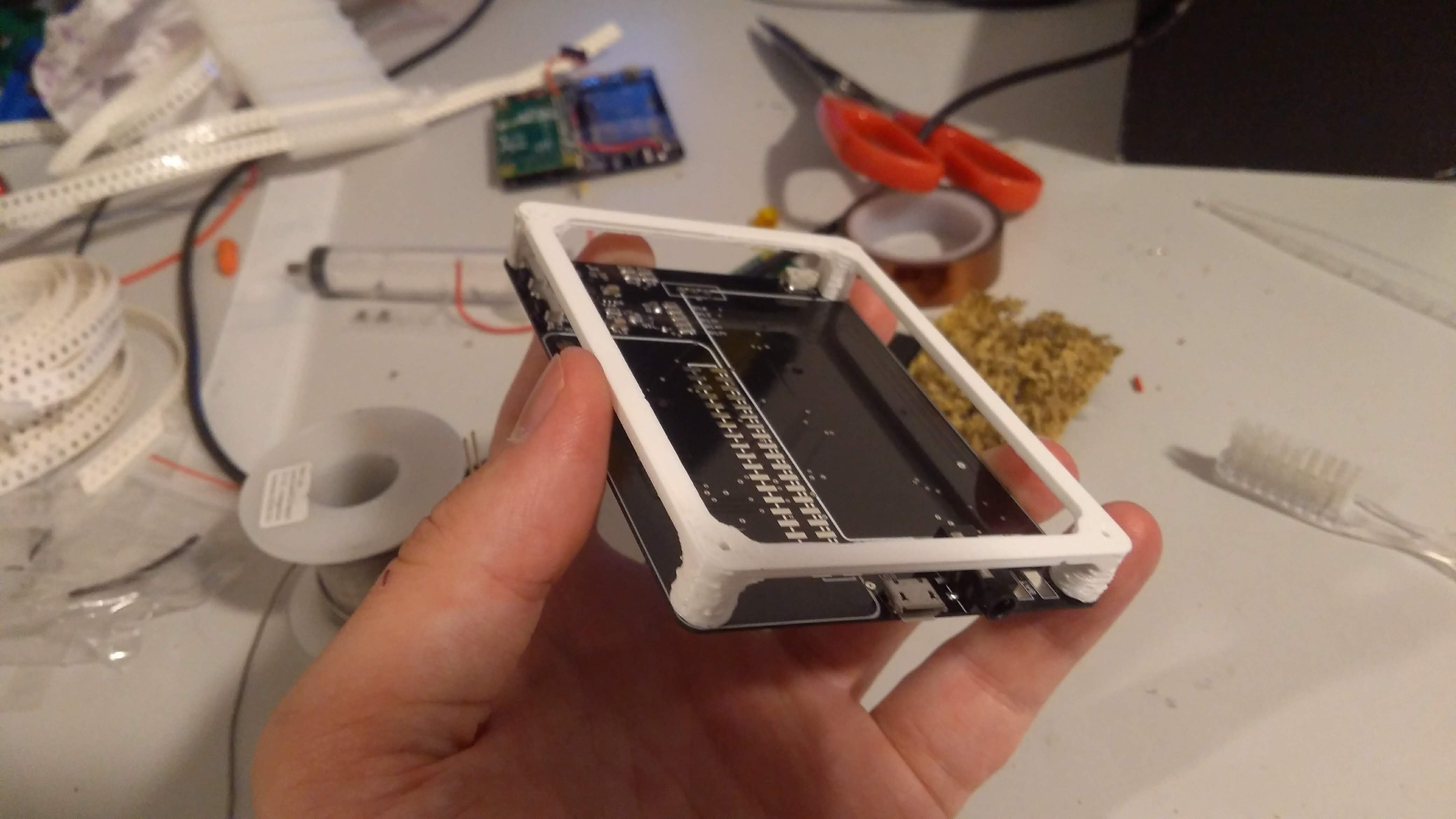
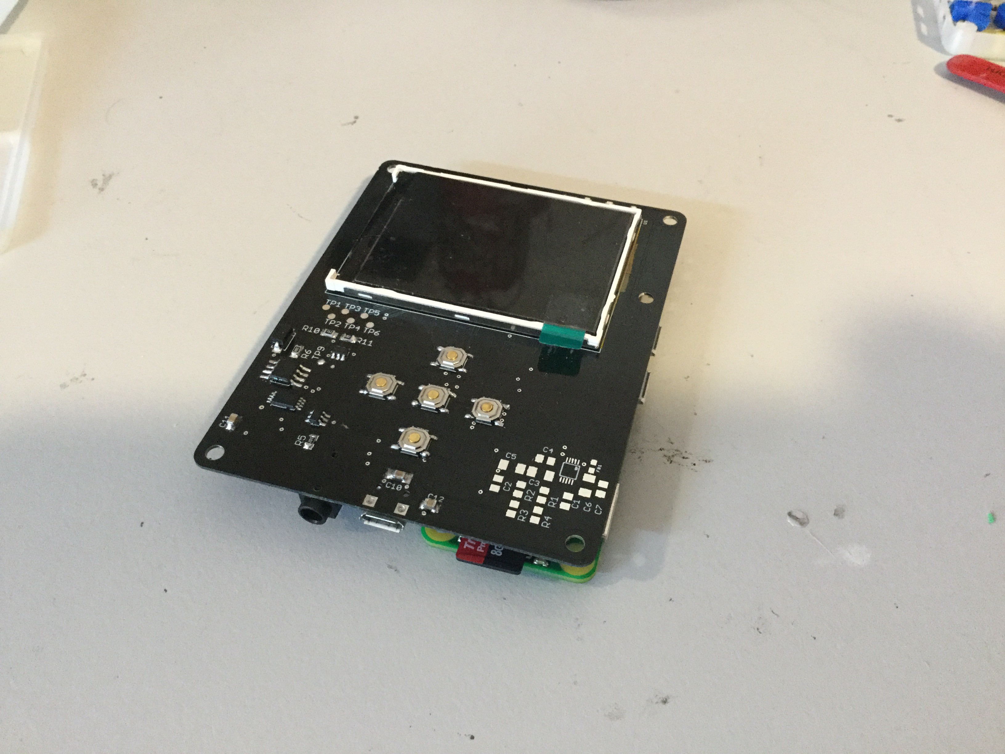
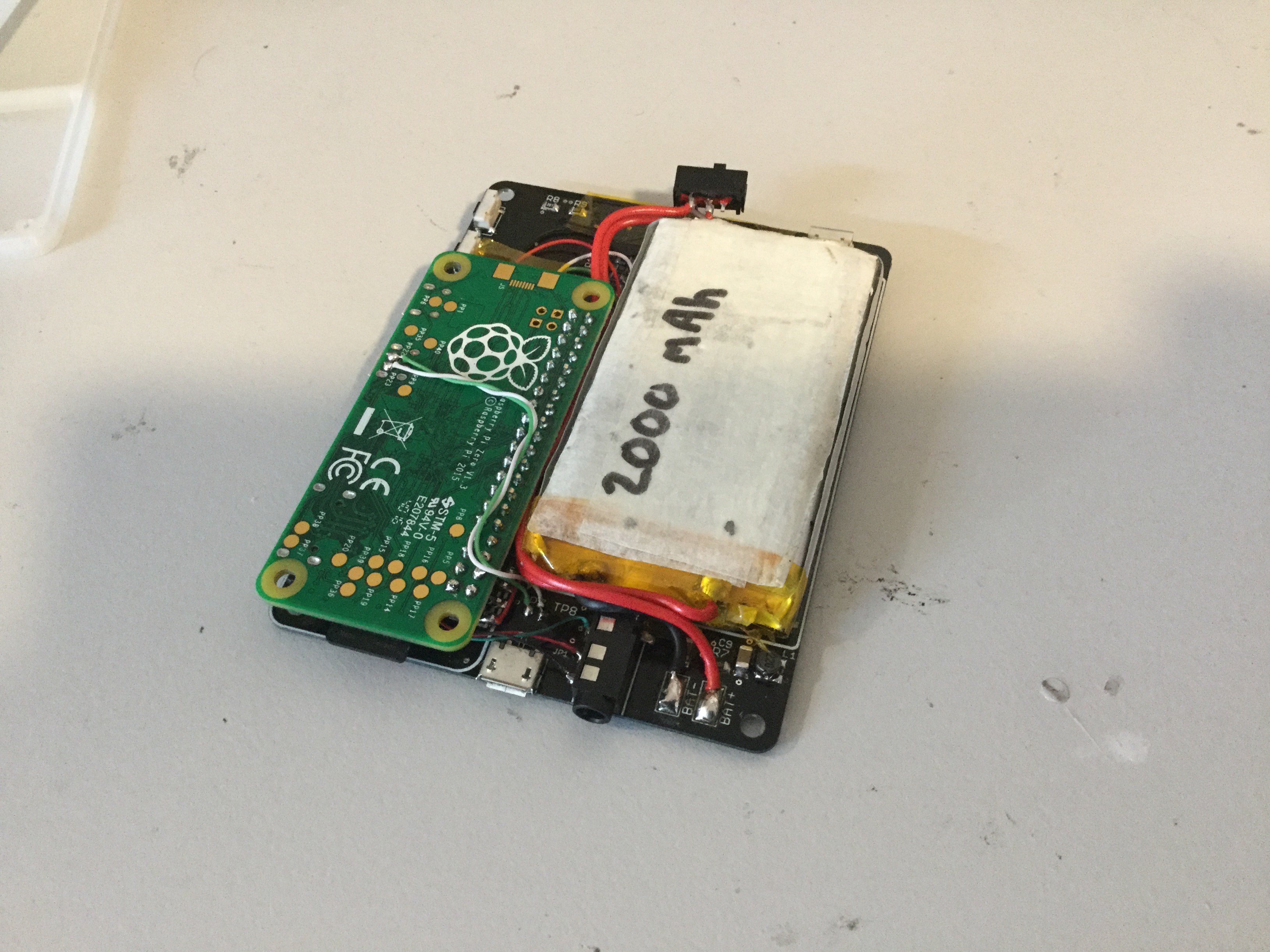
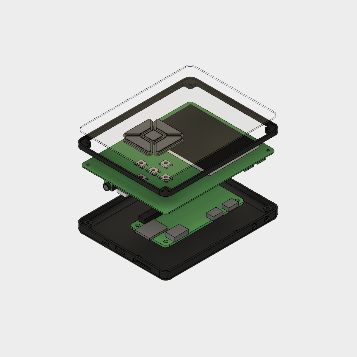
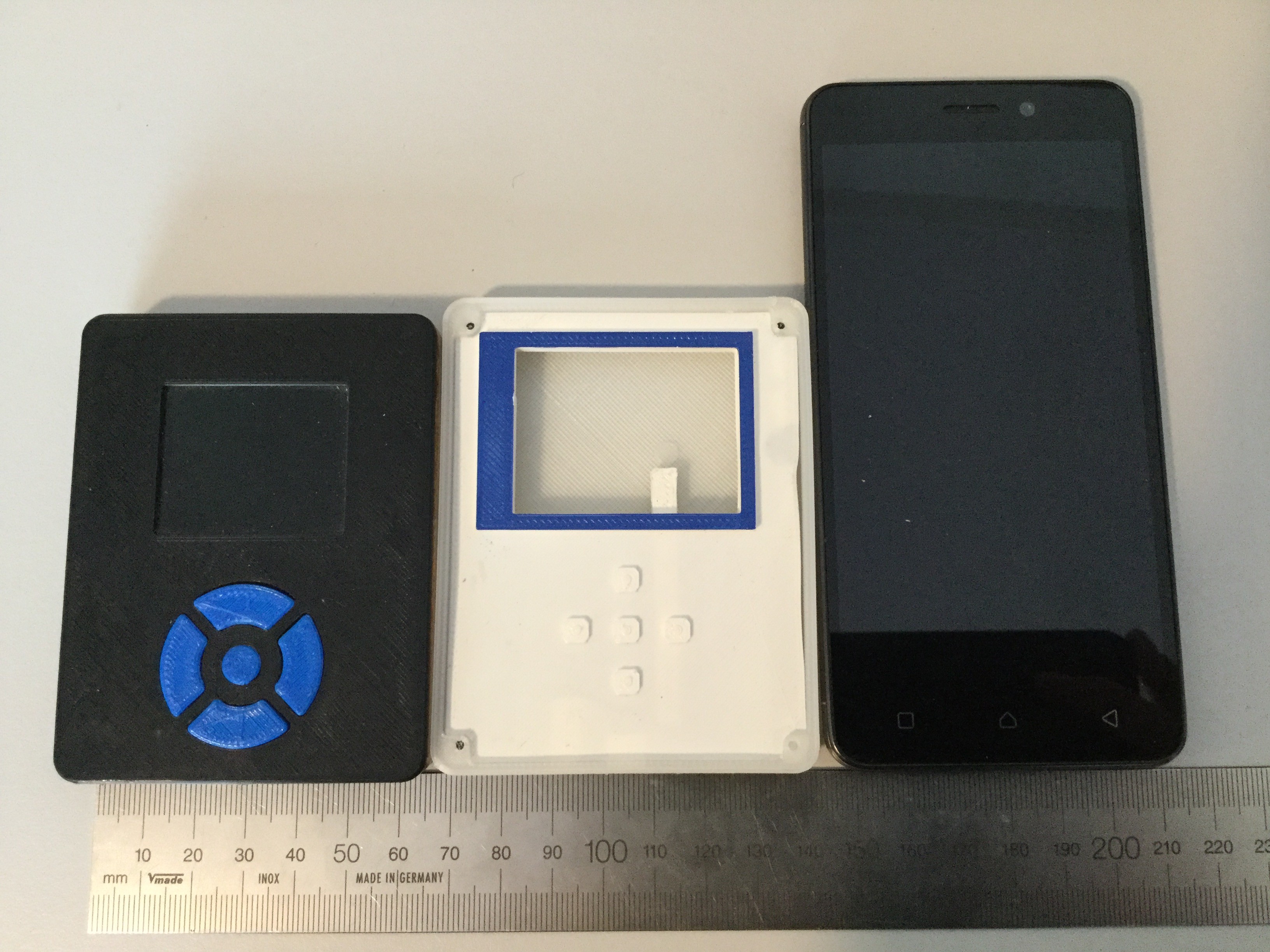
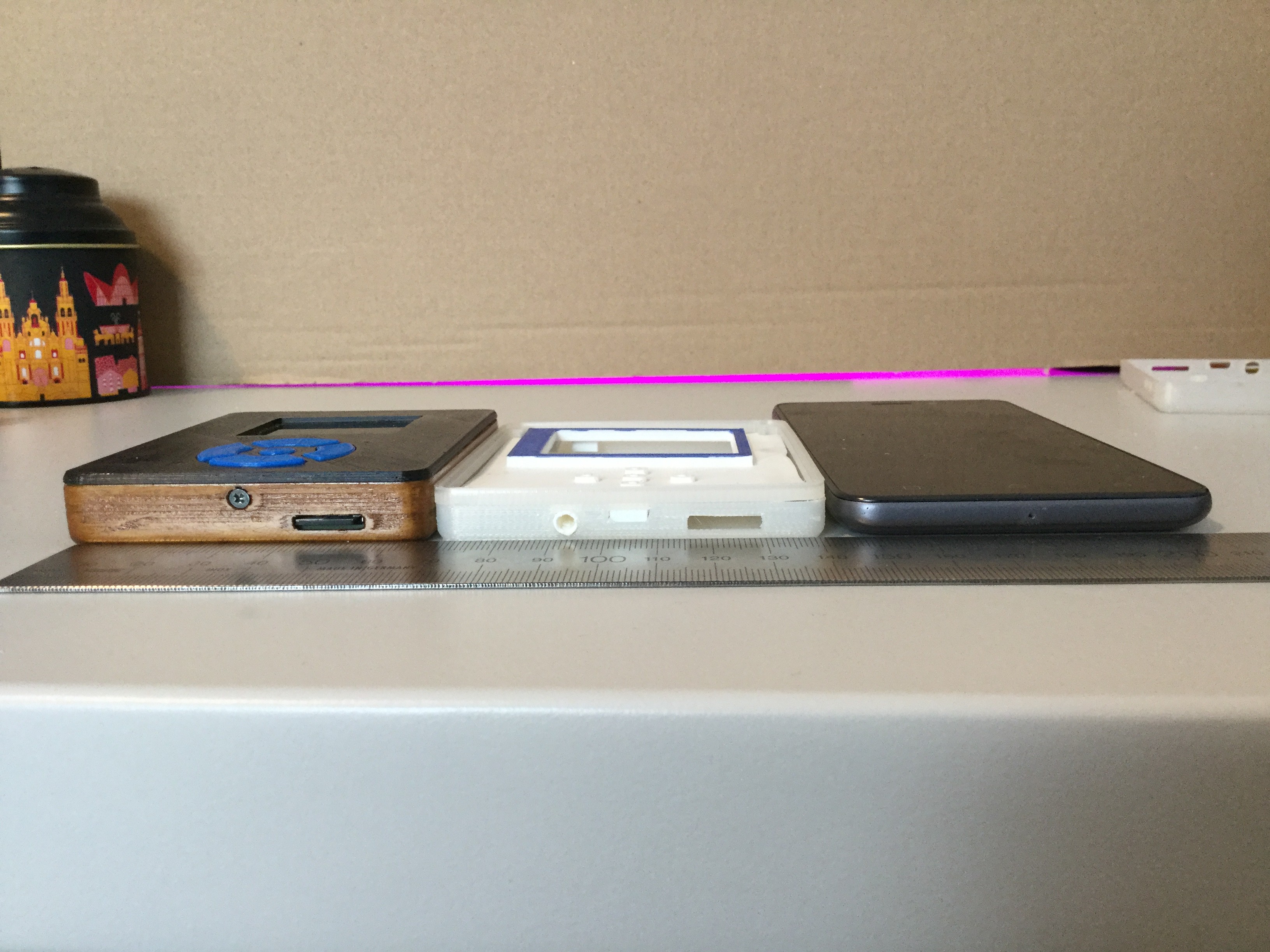
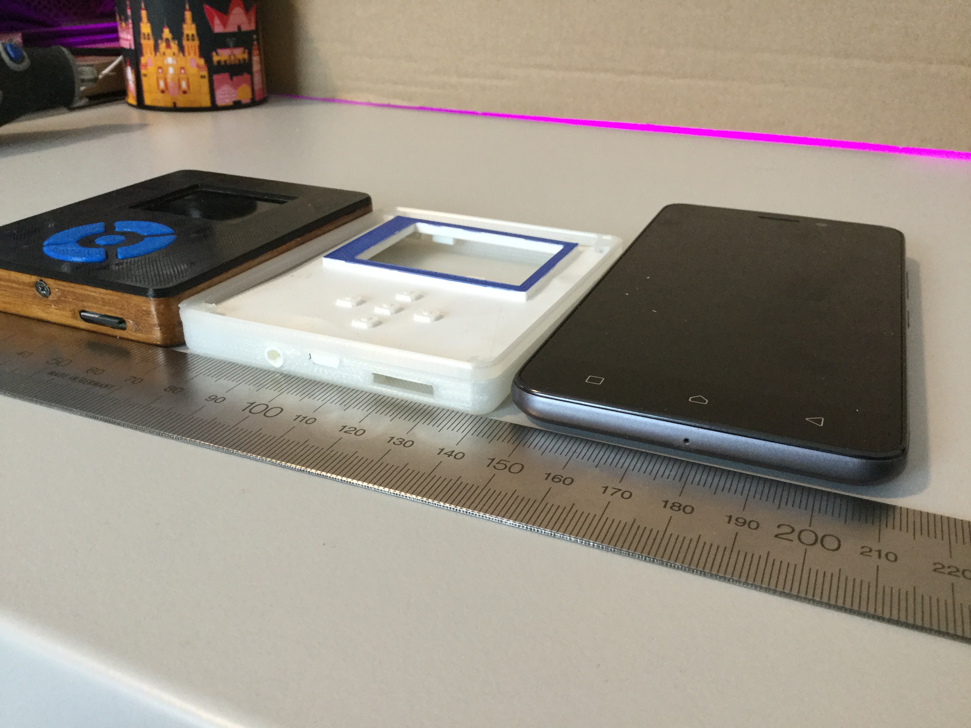
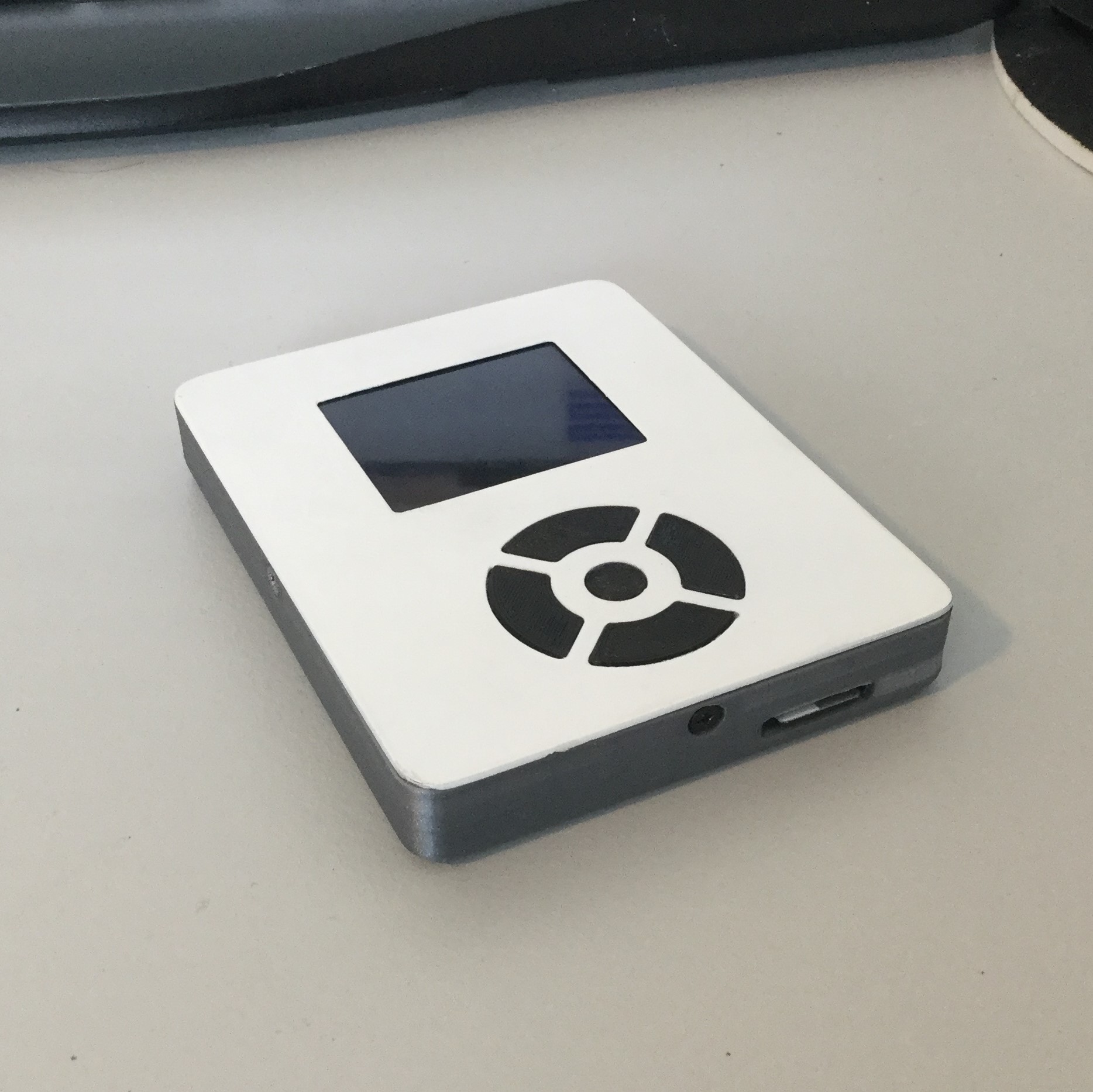
The next PiPod board will have a thicker PCB to make the device more rigid. The STL files for the case are already available on Thingiverse. These files are named: Top_1.6mm_.stl and Bttom_1.6mm_.stl. There's also a new frame for the inside available this frame is more rigid and fits the 1.6mm and 0.6mm board.
-
Update #10: Fusion design files, disc image and software tweaks
08/19/2018 at 20:37 • 1 commentMusic player interface update
I have been working on a new version of the music player interface. In this version, I switched from PyGame mixer to VLC because the support for more file types and to resolve some bugs that came from Pygame. I've also switched the library to read the metadata and implemented a new software structure.
Interface features
The current features include:
- Playing and indexing of MP3, M4A, WAV and WMA files
- Queuing of tracks, artists and, albums
- Displaying track metadata (song, artist and, album)
- Displaying song length and progress
- Detect charging state and displaying battery voltage
These are the most important features currently supported. It's pretty straightforward to add extra functionality that is in VLC player because it's used as backend (Thanks for the tip @Craig Hissett !).
Disc image
This new version of the music player interface is included in the disc image that I uploaded. This image has everything configured to start using the PiPod (except for the music ;) ). The buttons are configured using Retrogame, the display driver is loaded using modprobe and the musicplayer interface is started using systemd.
Fusion360 design files
The links to the Fusion360 design files have been added to the list of external sources. With these files you can tweak the components to make it fit your needs.
Instructions update
The instructions have been updated to include the disc image and have been tweaked a bit to fix mistakes.
-
Update #9: Final PCB
08/02/2018 at 17:32 • 0 commentsI have received and assembled the final version of the PiPod PCB in this version I replaced the CS4344 DAC with the PCM5102A, added the ADS1115 ADC to measure battery voltage and detect if it is charging and I redid the boost converter layout. I have also submitted the design of this board to the second PCB design challenge on PCBWay.
Assembly
I started assembling the bottom part of the board and used some 3D printed standoffs to easily assemble the top part. The information to assemble one of these board can be found on Github.


-
Update #8: New case and docking station
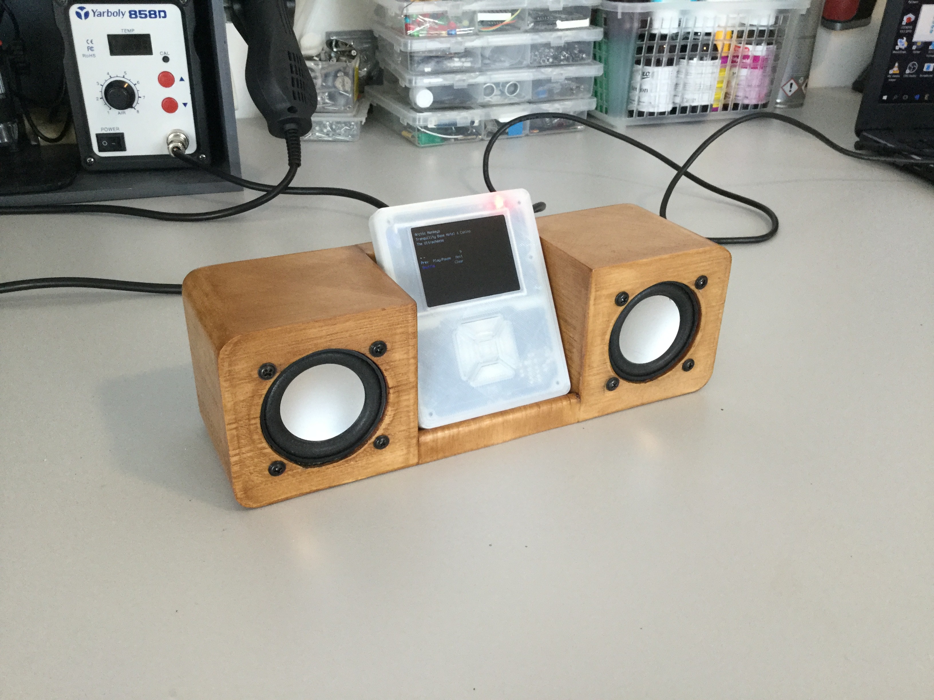
07/05/2018 at 15:37 • 0 commentsI have been working on a case for the new PCB and a docking station. The files for the docking station can be found on Thingiverse. I will release the design files for the case when I have a fully working PCB along with the PCB files.
More pictures and details of the docking station can be found here.


-
Update #7 Fully assembled PCB
06/12/2018 at 17:30 • 1 commentI have finally assembled a complete PCB, there are few change I will make on rev 2 but I have a prototype working. The power down function on this prototype isn't working yet and is kinda fixed by adding a slide switch. I've also decided to switch back to a PCM5102 DAC because I couldn't get a good enough clock pulse from the RPi to provide the CS4344 DAC with a MCLK. If I want to use this DAC I will have to add an external clock and for this I would have to redo the PCB and hope that I could get the drivers working. That's why I have decided to go back to the PCM5102 DAC on this prototype the DAC is sandwiched between the PCB and the RPi.


-
Update #6 First PCB received
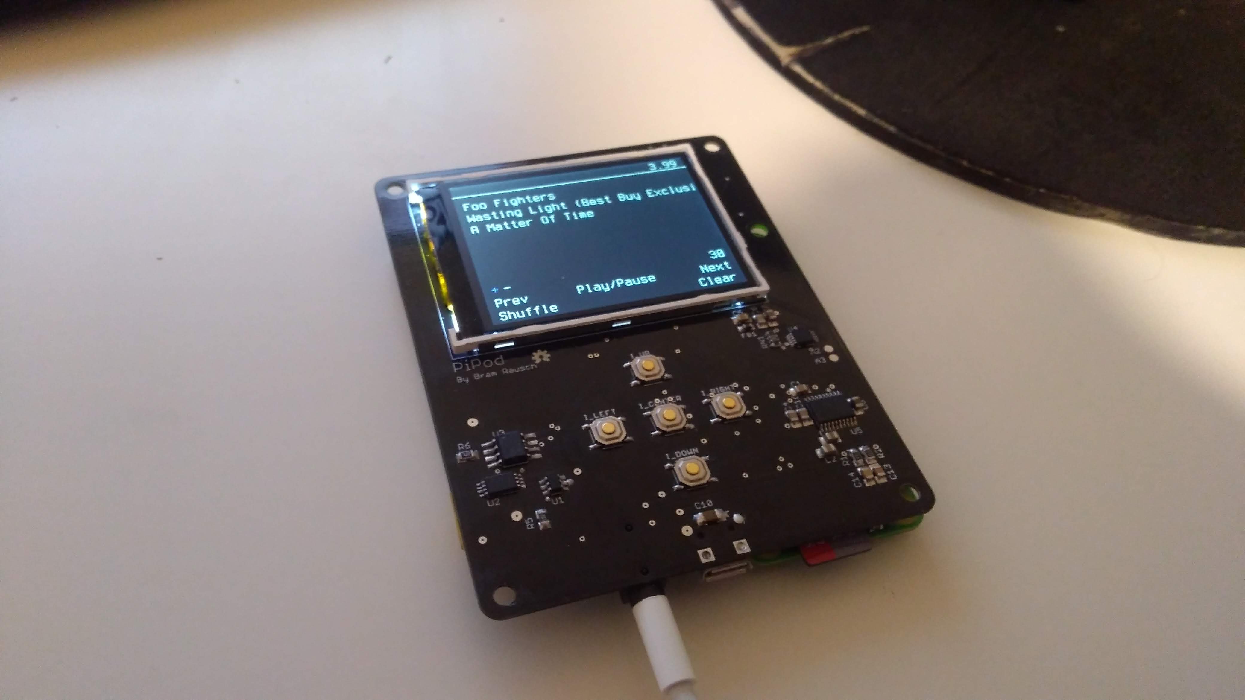
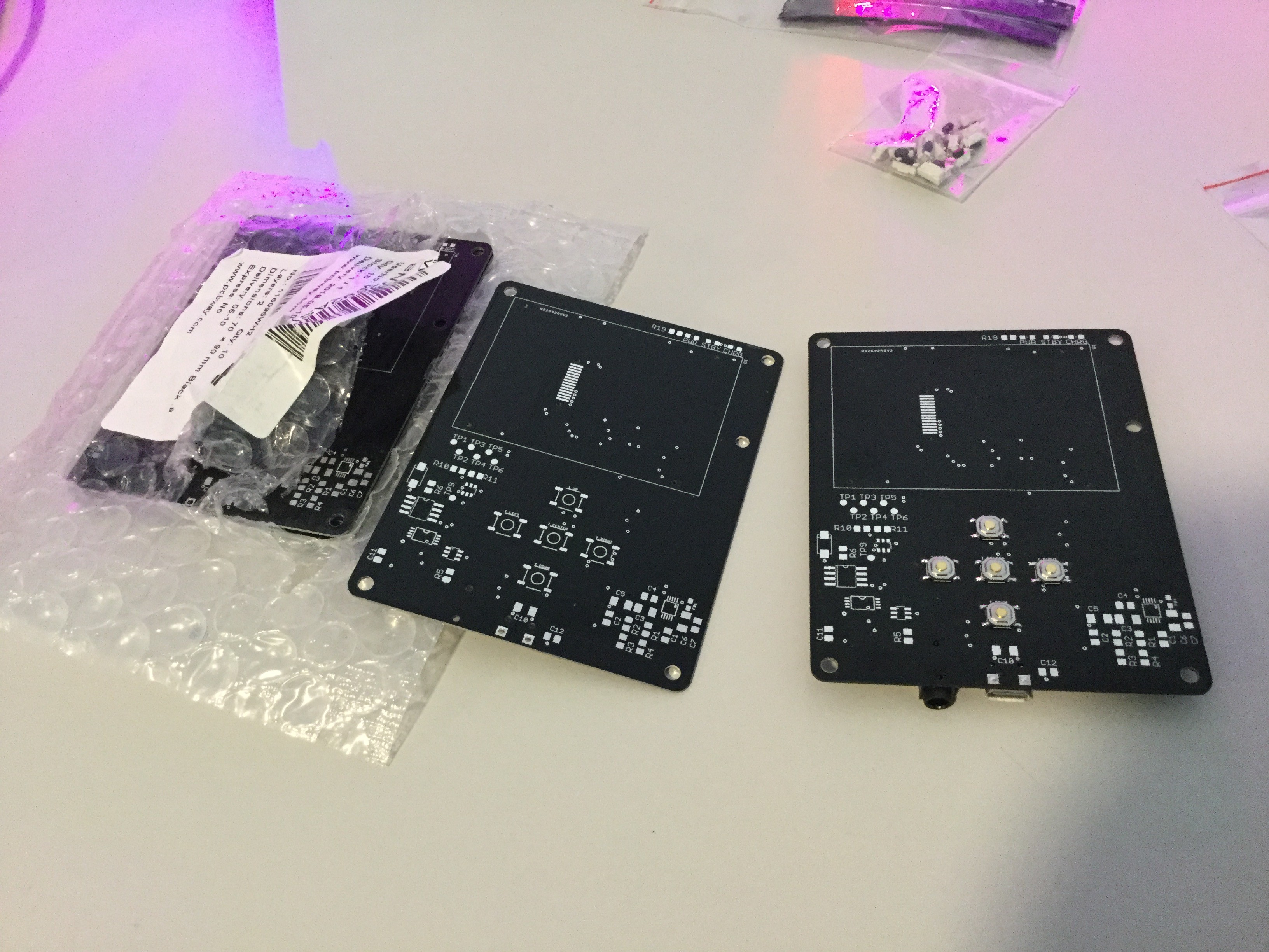
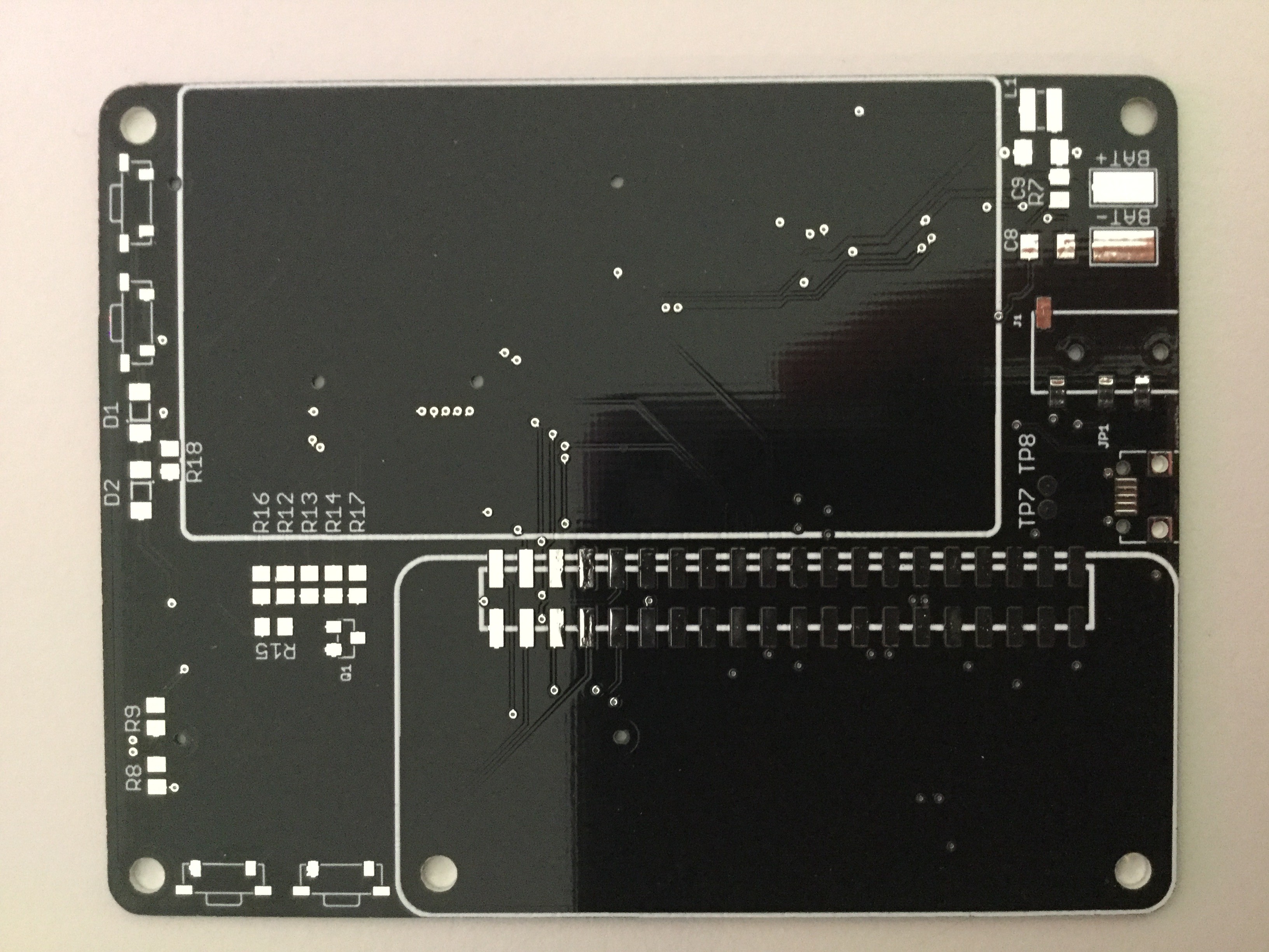
05/16/2018 at 19:18 • 1 commentToday I received the first version of the PiPod PCB from PCBWay surprisingly I received it earlier than the PCB's I ordered from Oshspark. I first wanted to test parts of the circuit with the boards from Oshspark but because the board from PCBway was very cheap I decided to order it. So here they are:

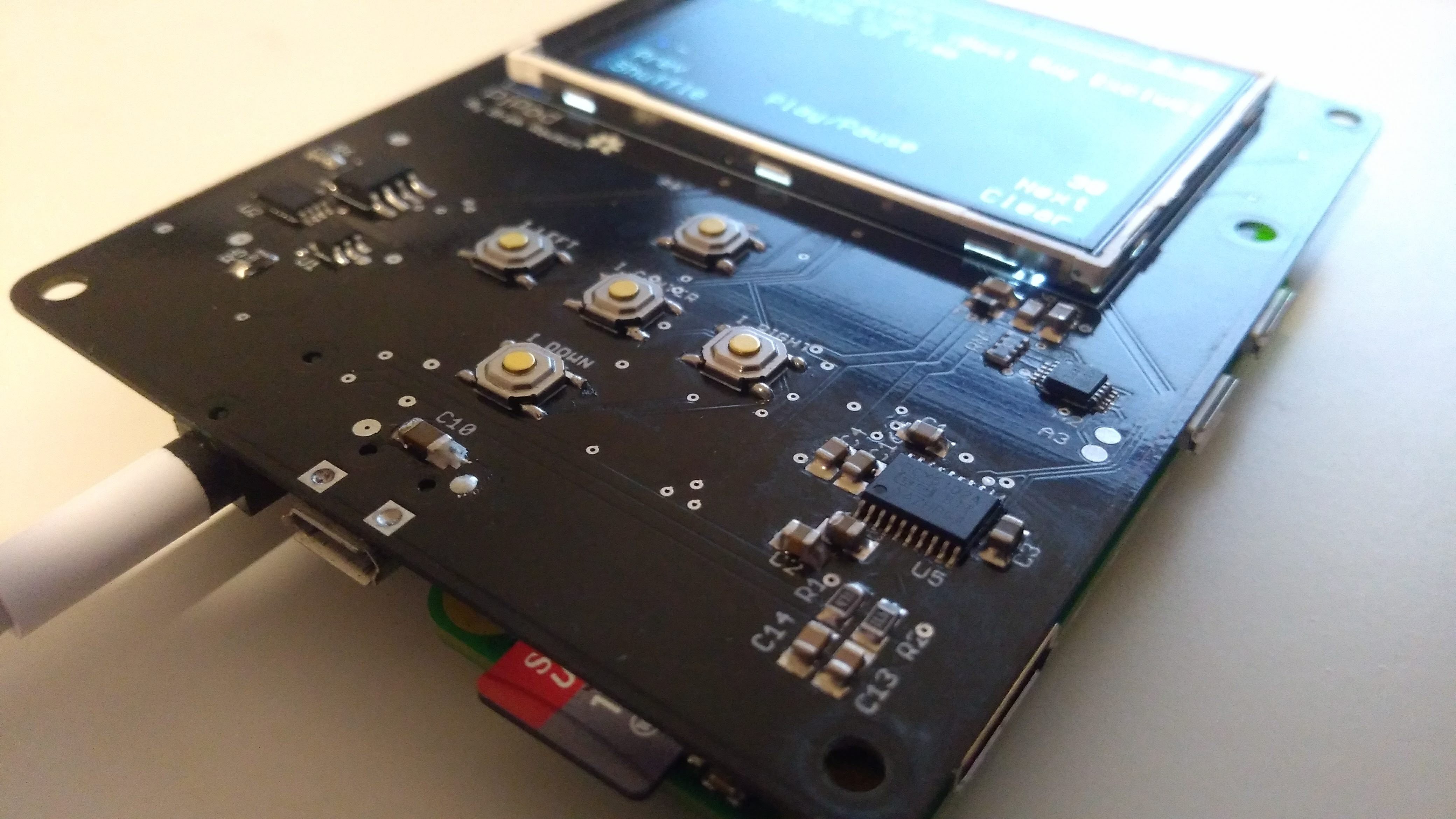
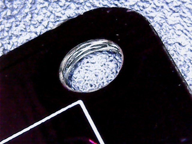
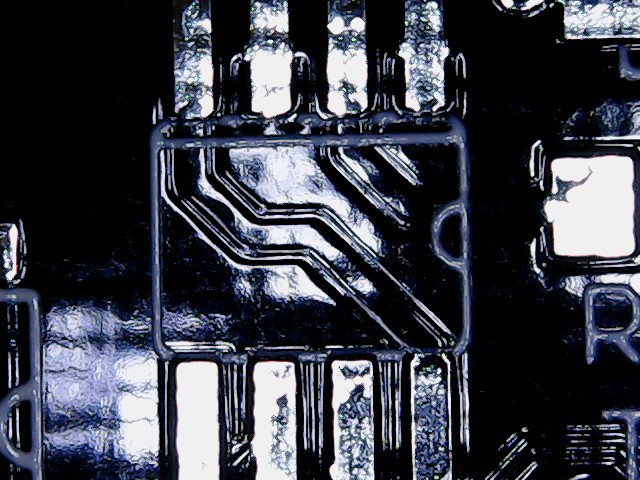
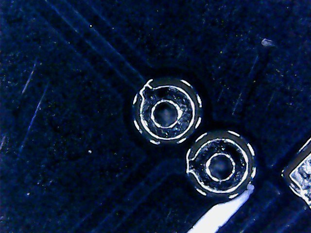
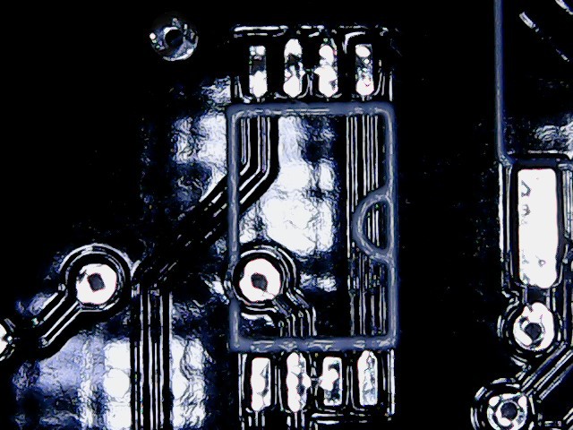
As you can see I ordered 0.8mm black PCB's this didn't cost anything extra. The boards come with HASL finish and an ENIG finish does cost extra but for this first prototype it doesn't really matter. When you select these options, the price is about the same as the Aisler and Oshspark boards the only difference is the quantity. The quality of these boards look good, the only quality issue I've found are the holes that aren't completely covered.

Here are some more close-ups:


I am still waiting on a couple of parts and when it has arrived I will assemble it further, for now I've soldered on the buttons to test the case.
-
Update #5 mockup of V2
05/14/2018 at 20:57 • 0 comments -
Project details V1
05/14/2018 at 20:14 • 0 comments Specifications
- 1200 mAh battery
- 1.8" TFT display
- 24-bit DAC
- Dimensions: 92mm x 70mm x 13,5mm
- On/Off switch
- 5 control buttons
- Music player interface
- Index music from
/Musicfolder - Sorting by artist, album and tracks
- Control volume
- Queueing
- Shuffling the queue
- Sleep mode (Backlight off)
- Display artist name, album title and track title
- Index music from
Why did I build this?
I had some spare time when I heard Apple was discontinuing their Ipod line. While I was reading about it I remembered that I had most part to build a MP3 player laying around, so I decided to build one.
Project cost
The price of this project is an approximation because I had most of the parts laying around.
Part Price Raspberry Pi zero € 5,50 I2S DAC € 3,00 1.8" TFT display € 4,00 Powerboost 500C € 17,95 1200 mAh battery € 11,95 64GB SD card € 30,99 Other small bits and pieces € 5,00 Total € 78,39 Resources:
Ethernet gadget:
- https://learn.adafruit.com/turning-your-raspberry-pi-zero-into-a-usb-gadget/ethernet-gadget
- https://www.mobileread.com/forums/showthread.php?p=3283986
Audio
- https://www.raspberrypi.org/forums/viewtopic.php?f=91&t=86609
- https://learn.adafruit.com/introducing-the-raspberry-pi-zero/audio-outputs
- https://learn.adafruit.com/adding-basic-audio-ouput-to-raspberry-pi-zero/pi-zero-pwm-audio
- https://support.hifiberry.com/hc/en-us/articles/205377651-Configuring-Linux-4-x-or-higher
-
update #4: Power button and custom PCB's
05/05/2018 at 23:03 • 0 commentsI am currently working on a single PCB PiPod. This new version of the PiPod will have a higher resolution display(2.2" 320x240), a bigger battery and a safe shutdown button. I have designed three small modules for the new parts that I want to use on this version these are currently being produced by @oshpark . While I am waiting on the PCB's and parts to arrive I am working on the final version that I want to verify with these small modules. These modules are also a great way to practice using my new reflow station before using it on the PiPod ;)
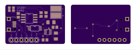
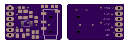
Charger 
Boost circuit DAC - CS4344 Safe shutdown
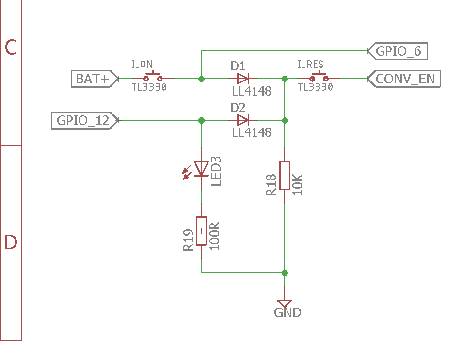
This power button circuit will make the Raspberry pi boot while the pi is booting it will turn on a GPIO that turns on the booster circuit and a LED to indicate that the power button can be released.
-
Update #3: Better audio
09/18/2017 at 20:46 • 0 commentsAudio output
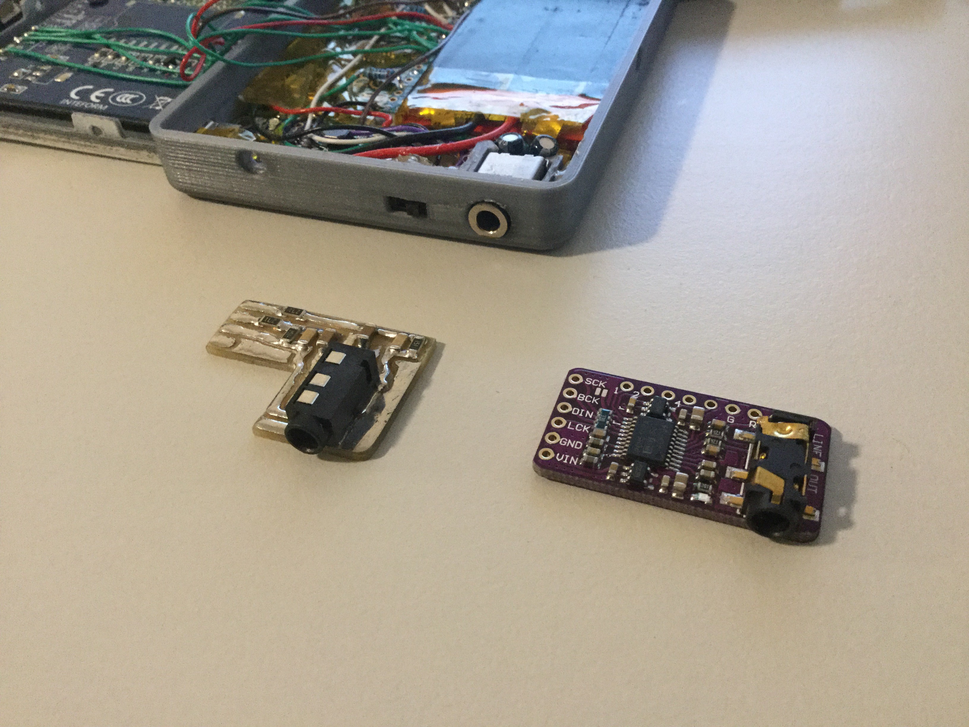
Recently I milled a PCB with the audio circuitry on it from the original RPi and when I received the little I2S DAC from China last week I compared both the boards on audio quality.
The quality of the dead bugged together solution was okay but it had a bit of white noise, I hoped that most of that white noise would be gone with the milled PCB but that wasn't the case. If the milled PCB wouldn't have had the white noise it would have been the perfect board because the audio quality was good enough (I only use it with earbuds) and it would have fitted better then the I2S DAC.
I was really surprised with the quality of the I2S DAC, it is really small and the audio quality is great. I have edited the case so it would fit this board, I had to make the walls a bit thinner at the top to have the extra space needed for the board but that is unnoticeable. I also moved the power switch to make some room for the component of the DAC and with all that extra room I added a extra screw hole because I noticed on the first version that the case didn't close properly. The updated case can be found on Thingiverse.
What's next?
The front part of the case is currently outdated but it still fits so I will keep it until I have decided what I am going to use as input method. I am currently looking at capacitive touch buttons and I will soon receive a kit of different kind of buttons I could try. If I have decided I will print a new front and mill a PCB for the buttons.
 bram
bram