This weekend I tested the RF synthesizer module for the network analyzer. It is essentially a two port signal generator which will inject a signal into the device under test. The module can spit out an output signal between 400 MHz and 13 GHz with an adjustable power level ranging from around -20 dBm to 10 dBm.
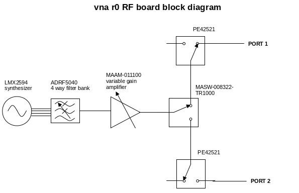
During testing I uncovered many many software bugs (this was my first time using a TI LMX2594) and a few hardware ones. Some of the highlights were that I flipped the polarity of the control signals into the high isolation RF switch (see the blue bodge wires below), soldered a filter in sideways, and messed up the feedback resistors on the amplifier that buffers and inverts the control voltage for the variable RF amplifier.
Here is a picture of the module after the repairs: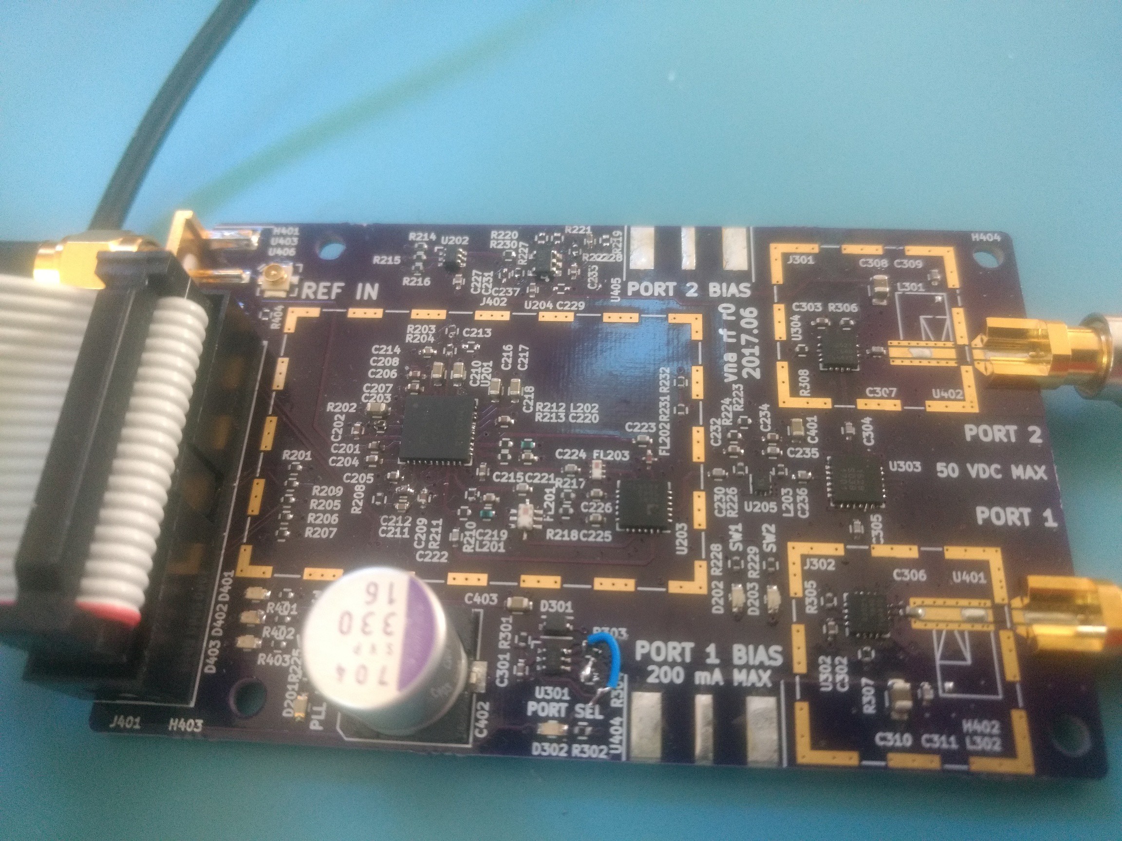
The two output ports can be fed with a DC bias input, this might be helpful for testing active devices like amplifiers. I didn't fully populate this yet because I want to make sure everything else is working before I plop down a pair of fancy $30 conical inductors. The board also has footprints for shielding, but those are also unpopulated until I've finished testing.
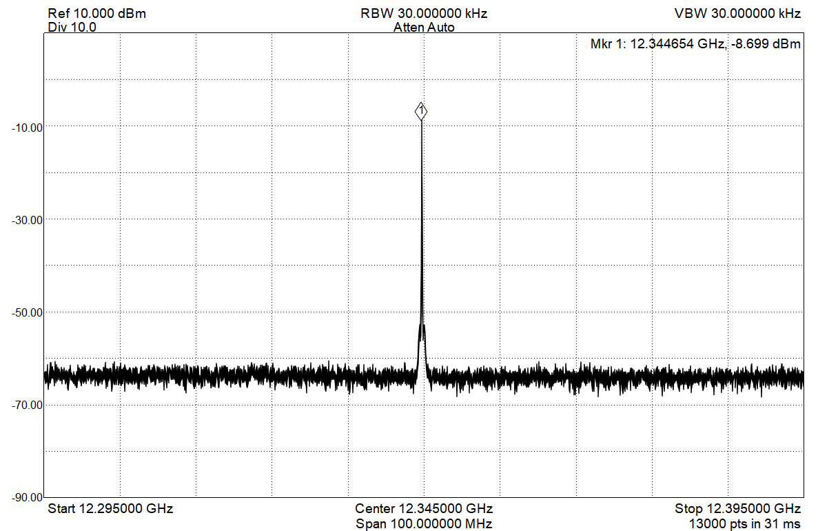
I spot checked a few frequencies on a spectrum analyzer to verify that the signal can work it's way through each path of the filter bank. Here is 12.345 GHz:
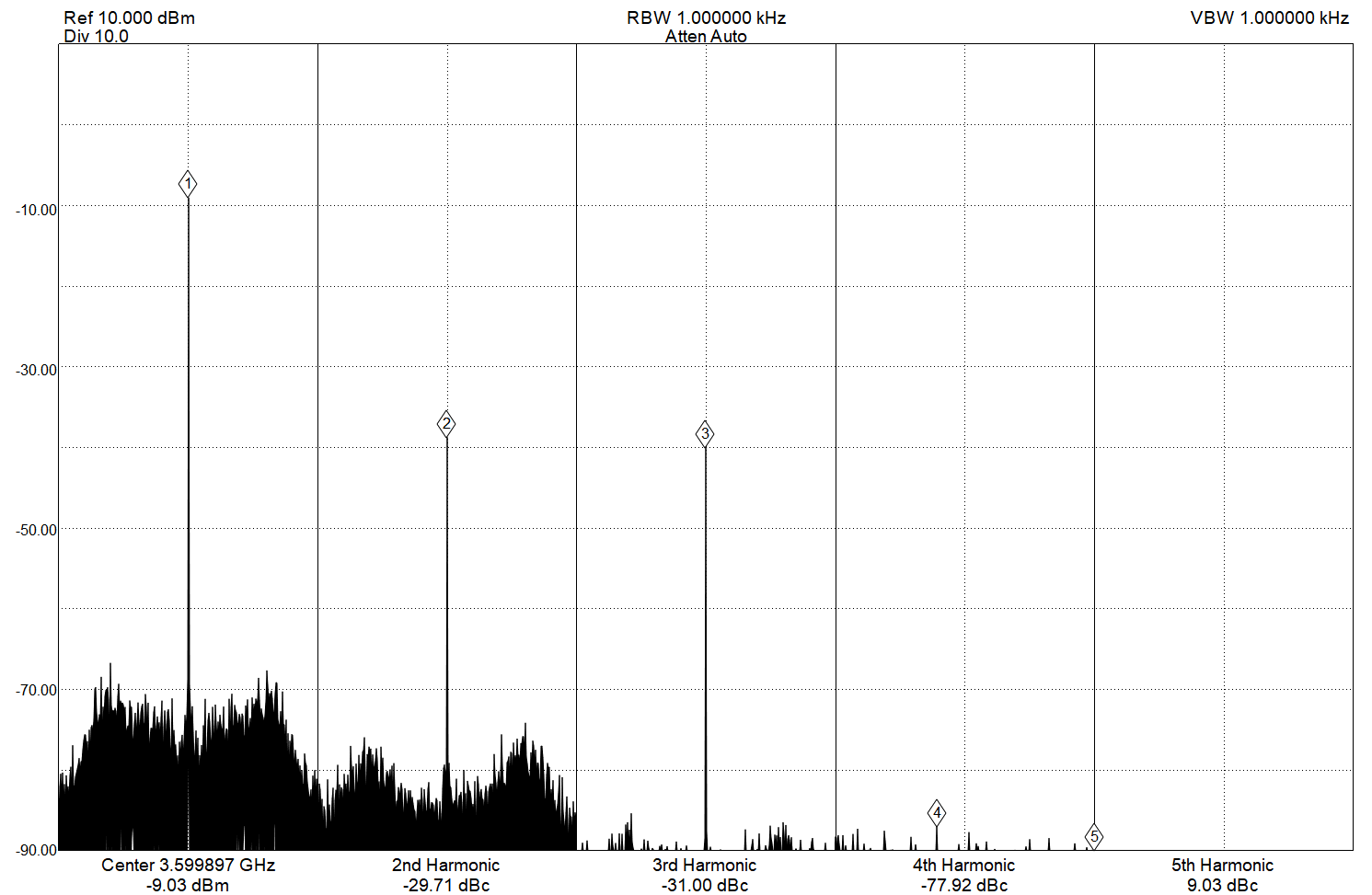
Here is a spot check of harmonics at 3.6 GHz. Harmonics will be very frequency and output power dependent, I may need to script up something to sweep this..
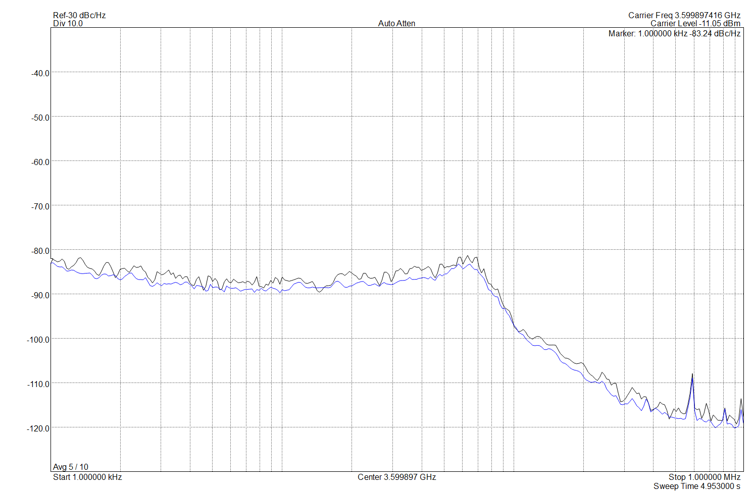
Phase noise isn't great, I still need to dive into the LMX2594 register and PLL loop filter:
Now that the RF board is mostly working, I'll move on testing the four channel demodulator board. The demodulator board also has a LMX2594 synth, now that I have a working LMX2594 driver testing should go faster.
 Jon Klein
Discussions
Become a Hackaday.io Member
Create an account to leave a comment. Already have an account? Log In.
Great VNA project I've viewed at this Hackday site! Thumbs up!
Are you sure? yes | no