-
Post LayerOne
06/01/2014 at 16:48 • 0 commentsWell layerone has been and gone, and apparently it was great, i don't know since i was in the back room getting a couple of hours sleep coding, while the others around me soldered boards together. I'm usually one to write up logs as they happen or just after, but this was a serious drain ( as well as the fact i have to delveop multiple hardware systems at work by siggraph), we're still building out badges.
Did the board work ?, yes it did, I missed one mosi line to the OLED so that was a kynar fix, but beyond that so far everything has worked, we read tags.
terribly grainy video
The HF/LF add on.
![]()
-
Finally all the PCB's in one place
05/21/2014 at 17:07 • 0 comments![]()
left side, LF antenna, middle HF antenna, right badge board, top combined HF/LF antenna.
The late nights/early mornings have started. The HF antenna is marginal right now so we just need to get the right caps/inductors added, but it did read. The LF of the combined card is working fine, HF side needs more inductors. RF is black magic.
![]()
There are tables strewn with parts as the kits are made, and we inventory everything for that last order for the bits that are missing or forgotten.
Hopefully tonight we'll get board built out.. Unfortunately our big laser is still in bits after the move, and the bits for the CNC mill aren't with the CNC..
-
Badge PCB's Arrived
05/20/2014 at 18:44 • 0 comments![]()
After delays, e-test errors, shipping problems, wild fires and 6 revisions. These completely untested hopefully 4 layer PCBs have arrived. I'm probably just being paranoid but they sure look like 2 layer.
Also Arrow decided that I didn't want overnight shipping for the CPU's even though we had a conversation about ground vs air and i didn't want to take the risk, so they chose to "upgrade" me to ground shipping from Reno, NV. Shipped last Friday, haven't yet arrived..
Thanks Arrow ! One of our family works at Arrow too, tsk!
Updated: The man from Extech says "Beep beep beep", coincidentally this is only piece of test equipment I have with me, and I saw it the other day thinking it was something else, then thinking whenever would i need that.. Few days later came in very handy..
Let the builds begin!
-
fedex and wildfires
05/19/2014 at 17:47 • 0 commentsIt's wildfire season, but Fedex managed to get our boards from Malaysia to us in good time, unfortunately there was a cock up in the ordering department and they shipped to the billing address, we'd left there about 15 minutes before they showed up with the package. So I signed for it online and it'll be left at the door tomorrow. I don't want to reroute it or go to the distribution centre, since Murphy's Law might kick in. The actual badges should arrive tomorrow at the right address, I did go and check. I also looked back on my order and it listed the shipping/billing address clearly four times, but they use paypal and paypal helpfully sends out another address.
Also Verical finally got back to me about my locked out, currently unknown password account, three days after I figured out how to get into myself and place the order. Same with Arrow, gave up and called in, have yet to see a tracking ID from them though. I have to say Digikey always impresses me on speed, sometimes they're just too fast, I've ordered something then 10 minutes later thought about another part to add, and too late its in the warehouse. Arrow/Verical do tend have some parts a lot cheaper though, often its parity with mouser/digikey but farnell/element14/arrow and verical sometimes have really good deals. Especially element14's part sales.
Allied are good too, Allied for Europeans like myself, are RS Components, my uncle used to work for them in the UK and he'd get me the giant paper catalogue that you normally needed to be a proper actual business at the time to get, it was the greatest thing ever. Now the paper books are mostly doorstops if they even exist. RS was this amazing thing in the sky that had all these neat impossibly expensive things, so Maplins it'd usually be. RS is Radio Spares, not tied to Radio Shack, or Tandy as it was in the UK.
Anyway we placed the hopefully final parts order from Digikey, Arrow and Verical. Parts we'd started off with had gone out of production or just not available, so a last minute late night dash to find replacements. Luckily it was just the MCP100T reset controller, so that is an easy move to the MCP800 series, the 16 MHz 2-SMD Xtal had a newer version, and a couple of other parts. I added each of the new parts in as OEM_ALT DIGIKEY_ALT etc in the attributes and checked in a new svn revision for each, that way we can see them in the log's clearly.
On Saturday i swapped out the STM32F1 chip for the STM32F4 on a 95% built prototype board, rather than scratch build a new one on the quick turn PCB's i'd gotten. All i had to do was carefully cut a couple of traces and put two 2.2uF caps on, i used a microscope and small knife to score away the traces. It's tougher than it seems, there are tools i've seen specific to that task, i've tried drills and snips etc, but this one was right a the leg of the IC.
After cutting away the traces I added the two caps the STM32F4 needs, and some kynar wire, and booted it up, the JTAG didn't see it at first, but seemed to be mostly an issue with the software side of things. A few unplugs and it worked fine.
It ain't pretty but it worked. The blue kynar wires are going to the caps. The Red wire is because we hadn't built out the battery charger circuit on this board, since we weren't sure about the values, it was built on a separate PCB
This is the battery test board, on the other side is a 5mm blue LED, we just let it charge and discharge daily. I'll try to add more details about this one, mmca is the one that put the circuit together, I believe its an iteration of the blinky ball. The chips used for the battery controller though might be getting tough to source, so might need to be revised in future.
Here is krs putting something on something, I don't recall what it is, but the blinding light from the scope is obscuring it
![]()
I think it was the antenna boards. For these we had to match the capacitors to get the best voltage at 125khz, so i pulled off the ones from the ref antenna to see what they were and measured it with some tweezers.
It came in around 960pF for a 1000pF part. I used one of the
![]()
It's not bad, shame it doesn't do inductance, that would have been really useful of course i had a high end LCR meter at my house for months while nullspace was moving, and we took it out the week before.
After getting a ball park capacitance reading, i used the proxmark to measure the antenna's output. I tried a few different values, deliberately choosing a value i knew would be off 33pF, to see the results, as expected. 125 is the desired frequency.
![]()
Note the different results at 1100pF, that is because I used a 1000pF cap and a 100pF together, same for the next couple i tried. the 1500pF was a single cap again. I think its worth checking this out some more.
I have a bunch of these cap kits from ebay, i don't suggest getting the ones in the black books, they're a lot more expensive , sure they're nice but they take up more space and it doesn't take too long to sort through a drawer of caps,. So i buy the refill kits
this guy has some of book kits cheap
http://www.ebay.com/itm/331052186099?_trksid=p2059210.m2749.l2649&ssPageName=STRK%3AMEBIDX%3AIT
Though I bought the kits from DIYGSM, i had a great experience with this seller, DHL lost some parts and he emailed me before I even knew about it, they contacted DHL , and sent me the whole set again before I even replied.
http://stores.ebay.com/DIYGSM-Wholesale
Each strip is individually marked too, i bought inductors, resistors, transistors, xtals and capacitors in sots, 0603,0805 and 1206 to add to my home workshop tool bins. Well worth it if you prototype a lot, I'm glad i very rarely have to read a resistor colour code band these days, I've always had a strong dislike for that system.
Also picked up a new scope, that i haven't had time to put through its places, I have a nice tektronix 4 channel 2024B, but liked this bigger screen, got it for $1,000 at frys.
Anyway back to the Saturday STM32 chip replacement. I already had STM32 Cube thing installed
http://www.st.com/web/catalog/tools/FM147/CL1794/SC961/SS1743/PF259243?s_searchtype=partnumber
So i figured, what the heck i'll give a go.
After about 10 minutes I had USB, and GPIOs all setup, some of the clocks figured out , but couldn't figure out why i couldn't choose the external XTAL on the clock page ( turns out its simple and logical, if you don't tell it on the pin page that a xtal is selected, it doesn't offer you the choice to do it, it'd have been nice if had given me a notice about it, but there you go)
After feeling pretty good about it, and relearning the again totally revised STM32 libraries ( third time that i'm aware of) i tried to bring up the 24Mhz TIM clock, no matter what i tried i couldn't get it running at anywhere close to 24Mhz, 4Mhz was the best i could muster. I wrote/rewrote the code, but usually ended up in the khz regions, so i left it for now with that sinking feeling that perhaps there was an errata or spec change, but I choose to ignore the elephant in the room for a moment. Added the OLED code and played around with it a bit. After an hour or two I went back to the clock, i pulled up the older version of the STM32 library, made the changes for it from the STM32F1 since the API had changed.
Didn't work... Forgot to add the stm32f4xx.s to the IAR project, added, and rebuilt, worked fine. So either its a problem with the Cube firmware , the startup code, or the libraries. Anyway I went back to the older version of the library API and started to add in the OLED ( realising that perhaps the reason i couldn't use HW SPI on it was that maybe i'd swapped MOSI/MISO on the board, i didn't want to look, i'd had enough heartbreak for the day ;) )
The OLED wouldnt boot, normally its really easy so i went back to look at the GPIO setup. Sure enough there are extra parameters that the later version of the library simplifies into one. Pullup/Pulldown/floating push pull/open drain etc. I added these and bingo it was up and running.
Next i added the SPI for the FPGA, had the same issue there, found some more parameters and then went over all the pins to make sure i'd gotten them right. Again the SPI library had changed from the STM32F1 style, so a few changes and it was up and running, I bit bang the FPGA so that was already going, the high speed slave mode of the STM32 is used for transferring the tag data to the CPU.
Then I switched on the DMA, lots of errors, again more big changes to the API. Changed what i could, and found very few examples the stream part threw me off for a while, i'd made my own local variable for it, and of course it didn't work, but it didn't work in a lot of ways, so having spent an hour on it , i moved on.
Next was the ADC's, again big changes , didn't work, changed the basic init code and i could read the ADC's normally, wasn't too bad and there are examples in the library, I tried to get the DMA code going but nothing, so after fiddling around a bit, I decided that i needed to just figure out why DMA didn't work on either since its basically useless without it, the normal read of an SPI is no where near fast enough for the FPGA reads.
After a few hours of head scratching, i came across the answers, one the address of the DMA , of course its a hard coded in a file somewhere, i didn't even think about it, changed that. Didn't work, then I took a look at the stream code setup, it just didn't make sense on how I though it was meant to be setup. That turned out to be the issue, again its a fixed structure in the library that you pass in, not your own.. Changed that and the DMA jumped into life for the ADC's
Applied the same fixes to the SPI DMA and it worked too, great!
I'd have liked to use the STMCube since its neat and the API is cleaner, but this one is just working for now. I prefer the revision of the stm32 library that the F1 uses, but that did take me a while to figure out the first time since it combines a lot of parameters in help functions and macros for the GPIO setup etc. The older library is mostly atomic so its obvious when you look.
I want to add the code for the DMA spi and ADC to this entry, but i just got called away for a fire, so i'll come back and add it. which also gives me time to update the SVN i have here locally.
I'm sure this post is already too long and meandering ;) but it is some of what i did this weekend.
code i' used for setting up a 24Mhz output on PA10, i haven't posted code on hackaday projects yet, so lets see how its formatted..
hmm double spaced, common HTML style editor problem
void SetupPCK0Clock ( void )
{
uint16_t Period;
GPIO_InitTypeDef GPIO_InitStructure;
TIM_TimeBaseInitTypeDef TIM_TimeBaseStructure;
TIM_OCInitTypeDef TIM_OCInitStructure;
Period = ( SystemCoreClock / 24000000 ); // Must be divisable
memset ( &GPIO_InitStructure,0,sizeof ( GPIO_InitStructure ) );
memset ( &TIM_TimeBaseStructure,0,sizeof ( TIM_TimeBaseStructure ) );
memset ( &TIM_OCInitStructure,0,sizeof ( TIM_OCInitStructure ) );
GPIO_InitStructure.GPIO_Speed = GPIO_Speed_50MHz;
GPIO_InitStructure.GPIO_Mode = GPIO_Mode_AF;
GPIO_InitStructure.GPIO_Pin = GPIO_Pin_10;
GPIO_Init ( GPIOA, &GPIO_InitStructure );
// Map TIM1 OC2/OC3
//GPIO_PinRemapConfig ( GPIO_PartialRemap_TIM1,ENABLE );
// Enable Timer1 clock and release reset
RCC_APB2PeriphClockCmd ( RCC_APB2Periph_TIM1,ENABLE );
RCC_APB2PeriphResetCmd ( RCC_APB2Periph_TIM1,DISABLE );
TIM_InternalClockConfig ( TIM1 );
// Time base configuration
TIM_TimeBaseStructure.TIM_Prescaler = 0;
TIM_TimeBaseStructure.TIM_CounterMode = TIM_CounterMode_Up;
TIM_TimeBaseStructure.TIM_Period = Period-1;
TIM_TimeBaseStructure.TIM_ClockDivision = 0;
TIM_TimeBaseStructure.TIM_RepetitionCounter = 0;
TIM_TimeBaseInit ( TIM1,&TIM_TimeBaseStructure );
// Channel 2 Configuration in PWM1 mode
// PWM1 gives a rounder pulse
// PWM2 gives a more pointed
TIM_OCInitStructure.TIM_OCMode = TIM_OCMode_PWM2;
TIM_OCInitStructure.TIM_OutputState = TIM_OutputState_Enable;
TIM_OCInitStructure.TIM_OutputNState = TIM_OutputNState_Enable;
TIM_OCInitStructure.TIM_Pulse = Period/2;
TIM_OCInitStructure.TIM_OCPolarity = TIM_OCPolarity_High;
TIM_OCInitStructure.TIM_OCNIdleState = TIM_OCIdleState_Reset;
TIM_OCInitStructure.TIM_OCNPolarity = TIM_OCNPolarity_High;
TIM_OCInitStructure.TIM_OCIdleState = TIM_OCIdleState_Set;
// TI CH3 Init
TIM_OC3Init ( TIM1,&TIM_OCInitStructure );
TIM_CtrlPWMOutputs ( TIM1,ENABLE );
// TIM1 counter enable
TIM_Cmd ( TIM1,ENABLE );
}
SPI2 Slave mode
/* Enable SPI2 Periph clock */
RCC_APB1PeriphClockCmd( RCC_APB1Periph_SPI2, ENABLE );
RCC_AHB1PeriphClockCmd(RCC_AHB1Periph_GPIOB | RCC_AHB1Periph_GPIOC, ENABLE);
// Inputs
// SPI SSP_NSS - PB12, SSP_CLK=PB13, SSP_MOSI = PB15
GPIO_InitStructure.GPIO_Mode = GPIO_Mode_AF;
GPIO_InitStructure.GPIO_OType = GPIO_OType_OD;
GPIO_InitStructure.GPIO_PuPd = GPIO_PuPd_NOPULL;
GPIO_InitStructure.GPIO_Speed = GPIO_Speed_25MHz;
GPIO_InitStructure.GPIO_Pin = GPIO_Pin_12 | GPIO_Pin_13 | GPIO_Pin_15;
GPIO_Init(GPIOB, &GPIO_InitStructure);
// Outputs
// SSP_MISO = PB14
GPIO_InitStructure.GPIO_Mode = GPIO_Mode_AF;
GPIO_InitStructure.GPIO_OType = GPIO_OType_OD;
GPIO_InitStructure.GPIO_PuPd = GPIO_PuPd_NOPULL;
GPIO_InitStructure.GPIO_Speed = GPIO_Speed_25MHz;
GPIO_InitStructure.GPIO_Pin = GPIO_Pin_14;
GPIO_Init(GPIOB, &GPIO_InitStructure);
// Setup as Alternative function
GPIO_PinAFConfig(GPIOB, GPIO_PinSource12, GPIO_AF_SPI2);// SSP_NSS
GPIO_PinAFConfig(GPIOB, GPIO_PinSource13, GPIO_AF_SPI2);// SSP_CLK
GPIO_PinAFConfig(GPIOB, GPIO_PinSource14, GPIO_AF_SPI2);// SP_MOSI
GPIO_PinAFConfig(GPIOB, GPIO_PinSource15, GPIO_AF_SPI2);// SP_MISO
SPI_InitStructure.SPI_Direction = SPI_Direction_1Line_Rx;
SPI_InitStructure.SPI_Mode = SPI_Mode_Slave;
SPI_InitStructure.SPI_DataSize = SPI_DataSize_16b;
SPI_InitStructure.SPI_CPOL = SPI_CPOL_Low; // high
SPI_InitStructure.SPI_CPHA = SPI_CPHA_2Edge; // 1edge // Sample on clock falling edge
SPI_InitStructure.SPI_NSS = SPI_NSS_Soft;
SPI_InitStructure.SPI_BaudRatePrescaler = SPI_BaudRatePrescaler_2;
SPI_InitStructure.SPI_FirstBit = SPI_FirstBit_MSB;
SPI_InitStructure.SPI_CRCPolynomial = 15;
SPI_Init ( SPI2, &SPI_InitStructure );
/* Enable SPIz */
SPI_Cmd ( SPI2, ENABLE );
DMA setup code
DMA_InitTypeDef DMA_InitStructure;
NVIC_InitTypeDef NVIC_InitStructure;
//DMA setup
DMA_StructInit ( &DMA_InitStructure );
// Enable DMA clock
RCC_AHB1PeriphClockCmd ( RCC_AHB1Periph_DMA1, ENABLE );
/* DMA configuration */
//channel 0, stream 3, rx, channel 0, stream 4, tx
DMA_DeInit ( DMA1_Stream3 );
DMA_ClearFlag(DMA1_Stream3, DMA_FLAG_TCIF3);//transfer complete
DMA_ClearFlag(DMA1_Stream3, DMA_FLAG_TEIF3);
DMA_ClearFlag(DMA1_Stream3, DMA_FLAG_FEIF3);
DMA_ClearFlag(DMA1_Stream3, DMA_FLAG_DMEIF3);
DMA_Cmd(DMA1_Stream3, DISABLE);
DMA_StructInit( &DMA_InitStructure );
DMA_InitStructure.DMA_Channel = DMA_Channel_0;//SPI2_RX
DMA_InitStructure.DMA_PeripheralBaseAddr = ( uint32_t ) &SPI2->DR;
DMA_InitStructure.DMA_Memory0BaseAddr = ( uint32_t ) buf;
DMA_InitStructure.DMA_DIR = DMA_DIR_PeripheralToMemory;// from device to cpu
DMA_InitStructure.DMA_BufferSize = len;
DMA_InitStructure.DMA_PeripheralInc = DMA_PeripheralInc_Disable;
DMA_InitStructure.DMA_MemoryInc = DMA_MemoryInc_Enable;
// a word is 32 bits... halfword 16 bit....
DMA_InitStructure.DMA_PeripheralDataSize = DMA_PeripheralDataSize_HalfWord;
DMA_InitStructure.DMA_MemoryDataSize = DMA_MemoryDataSize_HalfWord;
DMA_InitStructure.DMA_Mode = DMA_Mode_Circular;
DMA_InitStructure.DMA_Priority = DMA_Priority_VeryHigh;
DMA_InitStructure.DMA_FIFOMode = DMA_FIFOMode_Disable; //Operate in FIFO mode
DMA_InitStructure.DMA_MemoryBurst = DMA_MemoryBurst_Single;
DMA_InitStructure.DMA_PeripheralBurst = DMA_PeripheralBurst_Single;
//DMA_InitStructure.DMA_M2M = DMA_M2M_Disable;
DMA_Init ( DMA1_Stream3, &DMA_InitStructure );
/* Enable DMA Transfer Complete interrupt */
DMA_ITConfig ( DMA1_Stream3, DMA_IT_HT | DMA_IT_TC, ENABLE );
Enable DMA
DMA_Cmd ( DMA1_Stream3, ENABLE );
SPI_I2S_DMACmd(SPI2, SPI_I2S_DMAReq_Rx , ENABLE);Disable DMA
DMA_Cmd ( DMA1_Stream3, DISABLE );
SPI_I2S_DMACmd(SPI2, SPI_I2S_DMAReq_Rx , DISABLE);ADC DMA
This is for ADCing ADC1 0/1 to these two values.
// ADC values
__IO uint16_t ADC_Ampl[2];
void ADC_Configuration ( void )
{
ADC_InitTypeDef ADC_InitStructure;
ADC_CommonInitTypeDef ADC_CommonInitStructure;
#if DMA_ADC == 1
DMA_InitTypeDef DMA_InitStructure;
memset ( &DMA_InitStructure,0,sizeof ( DMA_InitStructure ) );
memset ( &ADC_InitStructure,0,sizeof ( ADC_InitStructure ) );
/* Enable DMA2 clock */
RCC_AHB1PeriphClockCmd ( RCC_AHB1Periph_DMA2 | RCC_AHB1Periph_GPIOA | RCC_AHB1Periph_GPIOB | RCC_AHB1Periph_GPIOC, ENABLE );
/* Enable ADC1 clock */
RCC_APB2PeriphClockCmd ( RCC_APB2Periph_ADC1, ENABLE );
/* DMA2 channel 0 configuration ---------------------------------------------*/
DMA_DeInit ( DMA2_Stream0 );
DMA_InitStructure.DMA_Channel = DMA_Channel_0;
DMA_InitStructure.DMA_PeripheralBaseAddr = ADC1_DR_Address;
DMA_InitStructure.DMA_Memory0BaseAddr = ( u32 ) &ADC_Ampl[0];
DMA_InitStructure.DMA_DIR = DMA_DIR_PeripheralToMemory;
DMA_InitStructure.DMA_BufferSize = 2;
DMA_InitStructure.DMA_PeripheralInc = DMA_PeripheralInc_Disable;
DMA_InitStructure.DMA_MemoryInc = DMA_MemoryInc_Enable;
DMA_InitStructure.DMA_PeripheralDataSize = DMA_PeripheralDataSize_HalfWord;
DMA_InitStructure.DMA_MemoryDataSize = DMA_MemoryDataSize_HalfWord;
DMA_InitStructure.DMA_Mode = DMA_Mode_Circular;
DMA_InitStructure.DMA_Priority = DMA_Priority_High;
DMA_InitStructure.DMA_FIFOMode = DMA_FIFOMode_Disable; //Operate in FIFO mode
DMA_InitStructure.DMA_FIFOThreshold = DMA_FIFOThreshold_HalfFull;
DMA_InitStructure.DMA_MemoryBurst = DMA_MemoryBurst_Single;
DMA_InitStructure.DMA_PeripheralBurst = DMA_PeripheralBurst_Single;
//DMA_InitStructure.DMA_M2M = DMA_M2M_Disable;
DMA_Init ( DMA2_Stream0, &DMA_InitStructure );
/* Enable DMA1 channel1 */
DMA_Cmd ( DMA2_Stream0, ENABLE );
/* Disable the DMA1 Channel1 Transfer complete interrupt */
DMA_ITConfig ( DMA2_Stream0, DMA_IT_TC, ENABLE );
#else
/* Enable ADC1 clock */
RCC_APB2PeriphClockCmd ( RCC_APB2Periph_ADC1, ENABLE );
#endif
/* ADC1 configuration ------------------------------------------------------*/
//ADC_InitStructure.ADC_Mode = ADC_Mode_Independent;
#if DMA_ADC == 1
ADC_InitStructure.ADC_ScanConvMode = ENABLE;
ADC_InitStructure.ADC_ContinuousConvMode = ENABLE;
#else
ADC_InitStructure.ADC_ScanConvMode = DISABLE;
ADC_InitStructure.ADC_ContinuousConvMode = DISABLE;
#endif
ADC_InitStructure.ADC_Resolution = ADC_Resolution_12b;
ADC_InitStructure.ADC_ExternalTrigConvEdge = ADC_ExternalTrigConvEdge_None;
ADC_InitStructure.ADC_ExternalTrigConv = ADC_ExternalTrigConvEdge_None;
ADC_InitStructure.ADC_DataAlign = ADC_DataAlign_Right;
ADC_InitStructure.ADC_NbrOfConversion = 2;
ADC_Init ( ADC1, &ADC_InitStructure );
/* ADC0 regular channel configuration */
ADC_RegularChannelConfig ( ADC1, ADC_Channel_0, 1, ADC_SampleTime_3Cycles );
/* ADC1 regular channel configuration */
ADC_RegularChannelConfig ( ADC1, ADC_Channel_1, 2, ADC_SampleTime_3Cycles );
/* ADC Common Init **********************************************************/
ADC_CommonInitStructure.ADC_Mode = ADC_Mode_Independent;
ADC_CommonInitStructure.ADC_Prescaler = ADC_Prescaler_Div2;
ADC_CommonInitStructure.ADC_DMAAccessMode = ADC_DMAAccessMode_1;
ADC_CommonInitStructure.ADC_TwoSamplingDelay = ADC_TwoSamplingDelay_5Cycles;
ADC_CommonInit(&ADC_CommonInitStructure);
#if DMA_ADC == 1
ADC_DMARequestAfterLastTransferCmd(ADC1, ENABLE);
/* Enable ADC1 DMA */
ADC_DMACmd ( ADC1, ENABLE );
#endif
/* Enable ADC1 */
ADC_Cmd ( ADC1, ENABLE );
ADC_SoftwareStartConv ( ADC1 );
}
-
anticipation, neoden, parts ordering, BOM.
05/17/2014 at 00:10 • 0 commentswe're still waiting on a tracking number for the PCB's, the conference is in just over a week! and i can't finish the code til we get the first one made... oddly enough this hasn't been the closest we've cut it, but its getting there.
since there is a huge disparity between vendors ( and findchips.com is so useful ) i've been trying to get parts from arrow for a while, they have my old address in there and only they can update it, i started requested that three weeks ago (and yes thanks Arko, i did try calling ) . Today I gave up and asked them to let me order it over the phone, of course the parts weren't in stock, even though they show up as in stock .
They found them on cut tape vs reel, and gave me reel pricing, so that was nice. I also picked up some SAM7 32KB's for people who just want a basic badge that does something. As with the last few L1's i'll probably spend most of the con writing code or building badges, my neoden TM220A is reeled up ready to go, ( don't buy the 220, get the 240 i didn't follow my own rule on this and it definitely wasn't a good idea.
Neoden are coming out with a new model as well, i'm guessing around June, but I'm also guessing it'd be a higher price, if you do buy from Neoden, don't accept the first quote, they'll drop the price.
I like the Neoden, its pretty straight forward, we have our Juki conversion as well, but that's at Null Space again and not in my garage, and its unlikely we'll get it set up in time, the TM220A I keep at home.
One of the problems I find we run into is that its easy to get into the mindset of buying parts from places like DIgikey who'll ship out a few hours after you order sometimes, so you think , yeah plenty of time! Since we're rev'ing the design as we go its been tough to order ahead, parts get forgotten about,. We use Google Docs Spreadsheet with a modified version of bom-xs.ulp to handle parts and ordering.
We set attributes in the schematic for each PART
MPN/PARTNO manufacturer part number (some BOM scripts use others)
DIGIKEY digikey part number, i'm going to change this next revision, and add DIGIKEY-REEL or something to specify reels etc for Jellybean parts.
OEM manufacturer
Here's an example of a part
![]()
I fill in the part number from mouser/newark etc ( you can see here MF is set to the wrong thing!)
It can also be exported to a database that you can share with others.
bom-xs.ulp creates an order, or parts list and then we can paste it into digikey, or arrows BOM managers and they'll quote it, as well as show parts that are duplicated or not available, expect that a lot!
![]()
Shown by Values
![]()
Also useful for handing kits, BOMs and just general checking. Document and update the attributes as you go along, consider ALT's as well. We've gone through a couple of BOM managers, but bom-xs has worked out the best for me so far, i even wrote a digikey scraper that pulled in parts to a local SQL database to get better matching than the website offers. But I didn't have time to finish it.
It can also query Digikey for pricing, but it needs some love on that side of things.
I've thought about trying to get this working with findchips to get the lowest price/quantity from whomever, but it isn't setup for that yet. I'm just glas it works as well as it does at the moment.
If you take enough care with the attributes and parts, you can pass on the list to other people, the more you do upfront and just as important, getting people to use computers to do the work, versus how we typically do it and end up doing all the slug work ourselves. Eagle does hard code some values into the part when you make it, so think about that, like a CPU that can be 32/128/256 variants, use the variants, all it does is change the name/value.
I wish eagle had more interactivity when its in a ULP, typically changes you do in the ULP , you generate a script, and run that on exit of the script, I also wish it was non blocking so i could keep working in Eagle while the BOM is open.
Another thing i'll do is export all the parts into a library, then replace it so its all tied together, the XML edit makes this faster.
-
Oh yeah I forgot.
05/12/2014 at 16:51 • 0 comments![]()
Not only does this badge have an FPGA, but there is also a breakout and chip pads for a BitFury BTC ASIC
![]()
-
LF Antennas arrived from PCB house
05/12/2014 at 16:43 • 0 commentsJust took them out of the box, need to test them and see if they've worked, RF is black magic.
The other boards are also out for manufacturing. They should be here this week , hopefully since we have to pre-build a bunch!
![]()
![]()
-
added a larger OLED
03/05/2014 at 17:58 • 3 commentsTerrible cell phone pic, the 1.3" 128x96 OLED SSD1306 is a direct drop in replacement for the 0.96".
Though it is $5.00 vs $2.57 , I do like the bigger display . I'll hopefully take a better pic of it, certainly couldn't take a worse one. It still has the plastic cover on it.
![]()
Compared to the 0.96"
![]()
These are remarkably easy to solder and desolder, lay a small line of paste over the pads and drag solder, then run the iron parallel to the edge connectors for each pad to clear up any bridges or excess solder , don't go nuts on the amount of paste.
To desolder all i did was gently lift one side at the right of the connect and slowly move the iron right to left over the pads and it just lifts off. i am using leaded solder.
-
timelapse of power and arm/fpga soldering up
03/03/2014 at 03:56 • 3 commentswe did a timelapse of arko hand assembling the first couple of rev3 boards since we can't pick and place them and test as we go along.
-
power....
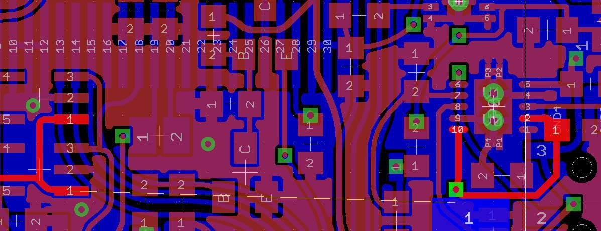
03/02/2014 at 19:18 • 0 commentsArko started putting the rev3 board together last night, we usually build the power section first and measure how it looks, make sure none of the power is shorted in the PCB ( it happens). This board has one always on regulator, its a 3.3V LDO that one didn't show up, the 5V in from the USB was there. But nothing else, hmm. did we not jumper the battery boost ICs since they're not yet populated ? Nope that was ok... I had the schematic open and sure enough... I see a problem, i highlight it on the board image in Eagle and Arko spots it next, we have friends over at the time and they're looking at us wondering we w're going 'uh oh'
Funny how everything looks obvious when you're looking for a fault ( the airwire I added after we found it, it just hasn't been routed yet, which in itself is also going to be a bit of a hassle, since technically unless i route it, its not a 2 layer board! )
![]()
The post boost 5V line isn't connected to the VDD, and i'm also thinking why does 5V still exist as a name ?
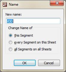
Well the reason is simple, and its caught me out a few times , even during this board.
![]()
I'd renamed 5V to VDD, but I did not change the "Change Name of" option from "this Segment" to "all Segments on all Sheets", simple as that. Once that OK button is clicked i severed the link between VDD and 5V and the board no longer had power, even though we all go over it a few times, no one spotted it. The worst part of this is that it casts doubt everywhere else, and maybe that signal that runs all over the place that just has a default eagle name of n$7 has been severed and it'll be really hard to spot. So i've never liked that particular option, Eagle doesn't remember what I last choose and there probably is a good reason they choose this way.
So we jumper from the VUSB in to a big pad of one of the caps and we're off, the 3.3V turns up, current draw looks fine.
![]()
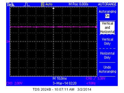
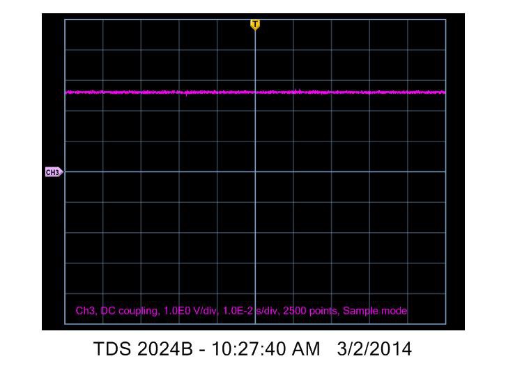
Tektronics software is awful by the way, i will tell you this boy, capturing a screenshot across the USB instead of the actual signal ? Madness, there is more data in the crappy image than there is in the waveform, i just don't understand the point of a screen capture transfer.. The best part is that on the scope if you use the save to disk option, it also captures the save to disk menu instead of the say for instance, much more useful measure screen. Of course you can use the other tek/visa software to download the waveforms instead, it'll install 10 or so background services that run all the time, and chew up a bunch of resources, then it'll transfer waveforms at the speed of mud, so much "scientific/test instrument" software is as clunky as this. The waveform Data Capture mode is equally slow but provides a much better image, but also much less data, wheres the useful measurements the scope provides, no axis levels, and for some reason a large white border? Wouldn't I rather have that are as screen real estate for the graph (or axis labels/measurements). again the other software does all this, but its just a royal PITA to use properly.
![]()
So screenshot has more information, crappier waveform and 1980's CGA bitmap stylings, waveform has less helper data, and a much nicer rendering with a giant border. Open Choice Desktop, thats my choice, poor processing vs a dozen installed services that do nothing 95% of the time my computer is running, it's become a real problem that software relies on background services that always run, so you just get bogged down with every updater app, or licensing daemon, its just not needed and poor design style.
Anyway, the FPGA and ARM are added next, ARM doesn't power up, this time I know what it is since we did this on the last board, there is a ferrite on VDDA that is missing and the ARM won't do anything without it, sure enough add it and the JTAG boots up and sees the chip, i flash in the rev2 software since the power on line is still the same and the FPGA jumps into life, it doesn't over heat so that's a good start.
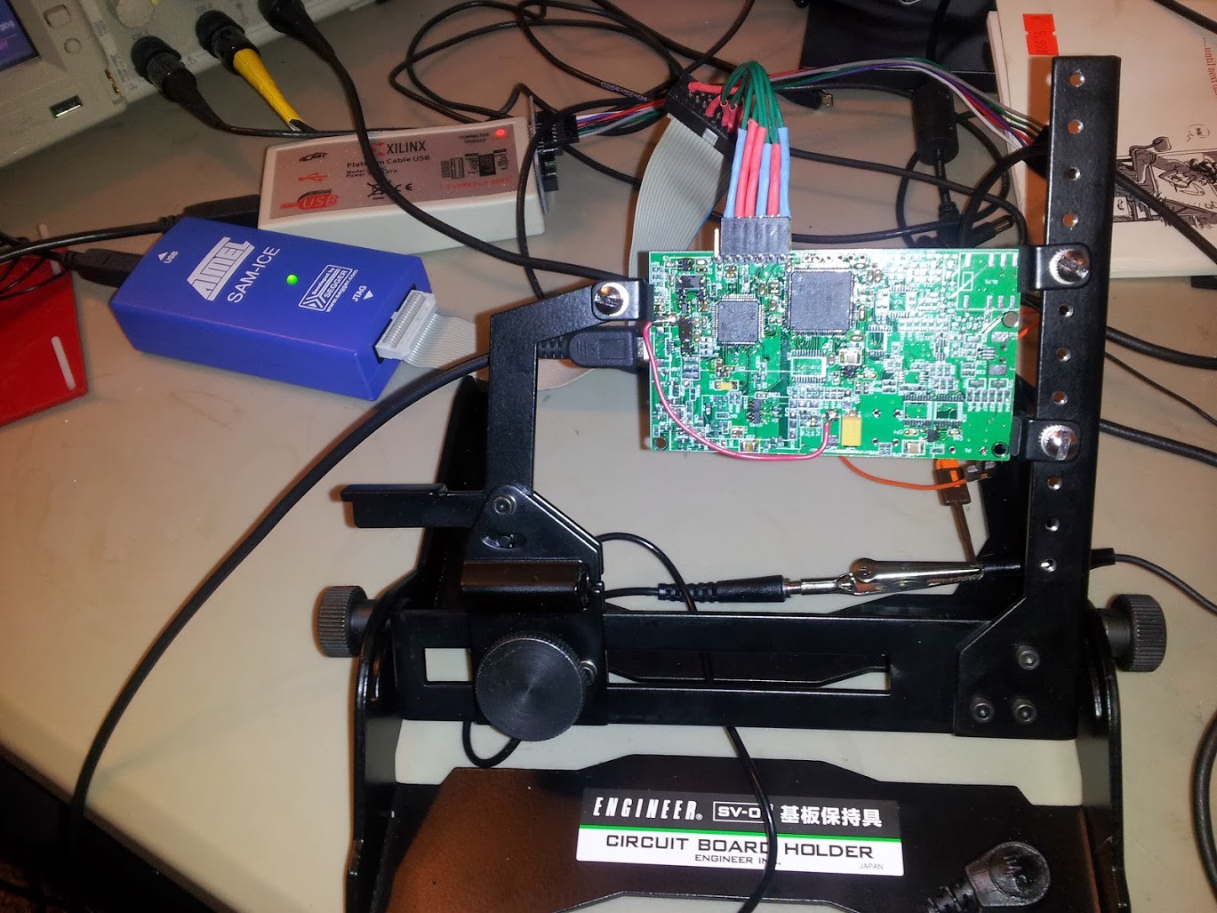
I add a define BOARD_REVISION ( 3 ) and start writing this blog, i also mounted the PCB into a neat PCB holder that Gleep had found in Japan and brought back for mmca, i ordered one directly form Japan, it's really neat, i use the panavises a lot but they are much to big for these size boards and deskspace hogs. Now i don't have to worry about ground wires flapping around and shorting out as well as giving a nice stable place for me to probe with the scope.
It's the engineer SV-D1, very handy
![]()
LayerOne 2014 Conference Badge
Electronic Badge, Based on the Proxmark3 with different FPGA, SAM7 , SDCARD and OLED
 charliex


