Richard Dudley
-
PhiDAC hex kits
05/30/2020 at 02:06 • 0 commentsIf you are curious enough to try your hand at a kit, you can go here for details of how to order : https://www.diyaudio.com/forums/vendor-s-bazaar/354799-phidac-hex-kits-pre-built-filters-new-post.html
-
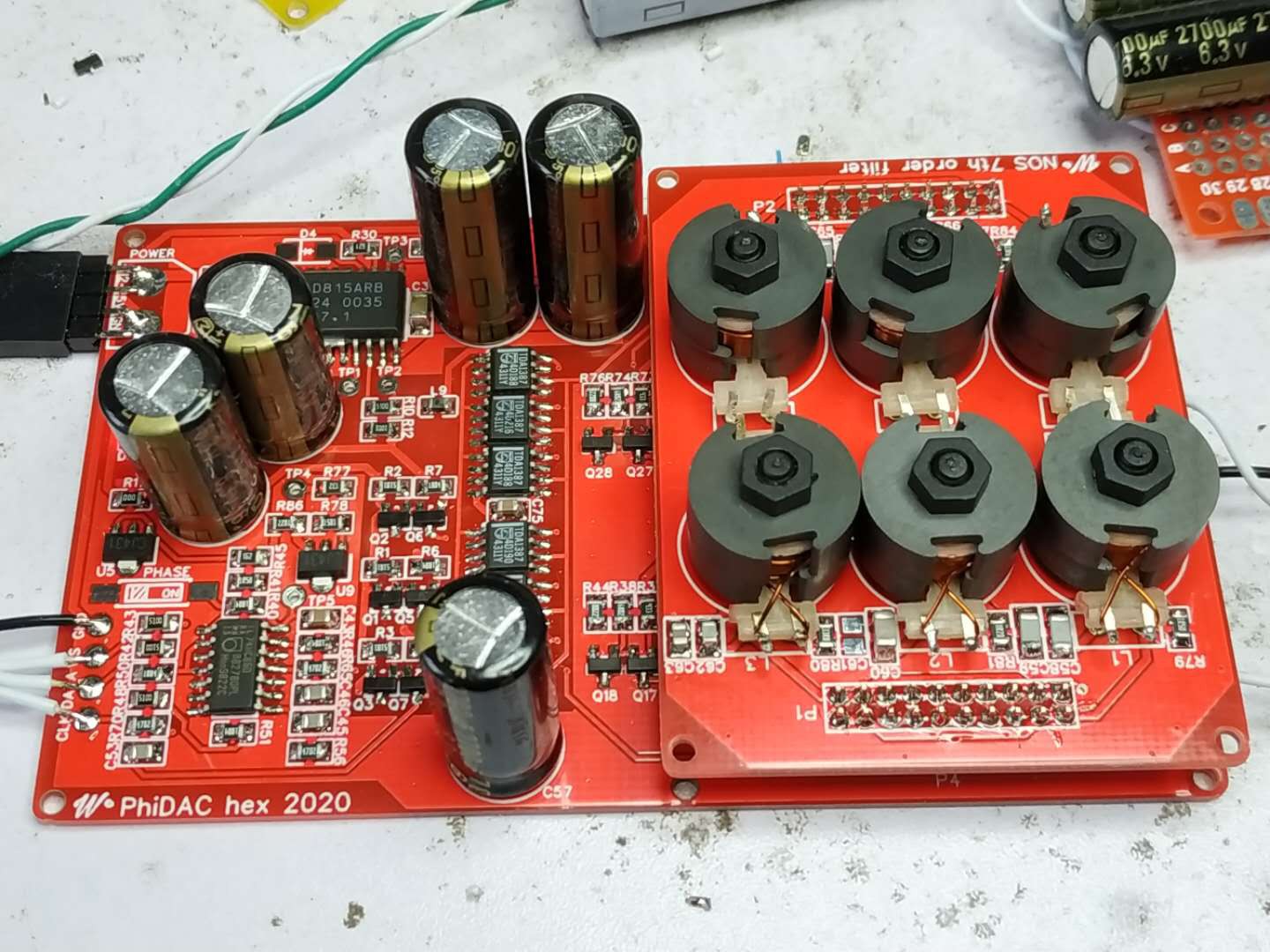
PhiDAC hex - 3rd generation PhiDAC
04/23/2020 at 06:57 • 0 comments![]()
Have built up two of these so far - 6 paralleled DACs and a 7th order filter plug-in.
-
Is there a sweet spot for number of paralleled DACs?
03/19/2020 at 02:46 • 0 commentsHaving found improvement from 4 paralleled chips I was curious whether further doublings of chips would lead to even more improvements. Going from 4 to 8 chips necessitated lowering the noise of the I/V stage in order to get some semblance of a level playing field for comparison. Already I was using paralleled stages as the opamp I used wasn't particularly low noise itself (AD744) - this opamp was chosen because I was wanting to experiment to see if I could improve the HF cleanliness and AD744 is one of the very few opamps which allows bypassing its classAB output stage (OPS). I really needed a bipolar input, undegenerated input stage opamp with a bypassable OPS to get the number of paralleled stages down to a manageable size. The opamp also needed to be cheaply available on Taobao. After a fairly brief search, I landed on AD829 - a part I'd never come across before but which fitted the bill perfectly. It also has a considerable extra advantage in that it is compensated for a minimum gain of 26dB - almost unheard of in opamps. Even 'decompensated' opamps usually have under 20dB minimum gains. This 26dB figure turns out to be a perfect fit for the I/V stage - its also under half the price of AD744 so all round an excellent solution here. A single AD829 with its 2nV/rtHz noise figure is a good match for 4 DAC chips, to go to 8 needs 4 paralleled for the same noise level as I want to keep the output compliance voltage constant meaning halving the LC filter's impedance. It took some layout tweaking to get the AD829 stable whereas the AD744 gave no issues whatsoever, eventually I got the AD829 array working and sounding great, slightly better (by which I mean more engaging) with 8 chips than 4.
So then what about 16 chips?
-
PhiDAC - the next generation
02/01/2020 at 03:44 • 0 commentsI've worked on the massively parallel DAC for a few months now and got to the point where I really need transformers made by a factory to create some kits for sale.. Winding them by hand is only my idea of fun when its a research project, not a commercial undertaking. Seeing as nCoV has hugely slowed commercial activity here in China I figured it would be quite some time before I'd get any significant volume of transformers (or even PCBs) made I therefore decided to re-visit the original PhiDAC (2019) once again and have a play with that design.
The two major attractions of the sound of 'grossDAC' over PhiDAC are considerably increased ambience and cleaner high frequencies. I began to wonder how much of the excellent ambience of grossDAC was due to the paralleling of chips and how much might be down to some effect of the transformers. Transformers I've used before on the output of my mobile phone gave a certain 'spaciousness' to the SQ which was alluring. Over on DIYA a contributor to my lingDAC thread had asked if it was possible to modify PhiDAC to accept 8 paralleled DAC chips, instead of the usual 1. The answer was a quite firm 'no' to that but I was curious how many extra chips might be OK to use.
4 chips turns out not to be too difficult. Just a few tweaks to gain and current sources (one of which controls the DC offset) with a cap change in the filter. What was surprising on listening was how much closer the SQ was to grossDAC in terms of the ambience. I'm not sure I'd be able to tell them apart on that aspect. My hypothesis is that the DAC generates some of its own LF noise which gets reduced 6dB when 4 chips are stacked up. Pretty damn encouraging for such a simple, cheap circuit.
So then, what about the HF 'haze'? Still working on that but adding more caps helped quite a bit with that on PhiDAC SE. For what I'm calling 'PhiDAC Quad' I don't want to go to such complexity as an additional PCB for caps so I'm experimenting to see if there are any other ways around this.
Another thing I've discovered is that under certain conditions the MLF2012 inductors used in the passive filter generate some measurable distortion. This might be because I'm using them close to their maximum rating (5mA) - 4 chips running at 6V put out 4.8mA max. So I'm exploring different inductors and slight variations on the basic filter configuration.
-
How a transformer helps...
07/16/2019 at 09:04 • 0 commentsTransformers are usually described in what I'll term the 'voltage domain' - that is in relation to the voltages across their windings. Under this tradition, the term 'step up transformer' refers to one with a higher voltage on its secondary than its primary. It seems to me equally valid to describe transformers in the 'current domain' too, in which case a 'step up' would be one which gives a higher current on its secondary than its primary. The transformer which does 'step up' in the current domain simultaneously does 'step down' in the voltage domain. The two 'domains' are completely equivalent and just a matter of perspective, but I find I need to adopt one perspective or the other in order to think straight about trafo design. Swapping between them gets very confusing very quickly!
Why talk about transformers in terms of currents, thereby swimming against the tide? Simply because the DACs I'm using are current output types, not voltage. From now on, when I talk 'step up' or 'step down' I'll be writing in the current domain, the opposite of the normal way of speaking of trafos. A trafo to provide a low impedance on its primary and a much higher one on its secondary is called a 'step down' in the current domain. The input current is higher than the output. Given we've not got a lot of current coming out of a single DAC chip (at most 1.2mA peak-peak) we'll need a few of them in parallel when using a step-down transformer in order to get a useful amount to feed into our I/V.
Circuits I've seen which use transformers (step down ones) in conjunction with DACs (AudioNote had a patent on this, now expired) tend to put the I/V resistor on the transformer's primary and then have more turns on the secondary to increase the voltage. To use passive I/V on the DAC's output directly seems to me to be taking a step backwards (been there, done that), so I prefer to use the trafo in 'current mode' and have the I/V stage (either active or passive) on the output (secondary). One transformer manufacturer says this sounds better - perhaps because the trafo's leakage inductance is providing useful low-pass filtering in this mode. A rule of thumb I've learned with trafos in 'voltage mode' is that they do need to be driven by the lowest possible impedance. The dual of this rule would seem to be that running in 'current mode' a trafo should be driven by the highest possible impedance - a TDA1387 output is certainly that.
Designing a transformer in 'current mode' has taken some getting used to and I'm not yet anywhere near as proficient in thinking about trafos in this way - the equations for their design are still talking about voltages, not currents. So I did one or two experiments in an attempt to prime my intuition. The first thing I discovered was that primary inductance matters - its a major contributor to the low-frequency roll-off. In conjunction with that, primary DCR matters too. In an attempt to maximize the primary inductance I have gone over to a higher mu core material, its downside is that it permits a reduced maximum B (around 0.25T) compared to the lower mu ferrite I'm used to using (~0.35T). I have very few core sets with the high mu material so I began with an EP17. This core has one major advantage in that its a horizontal configuration (most ferrites adopt vertical configs) so the winding doesn't need to go up and down, just left to right. Better winding flexibility.
My rule of thumb for a trafo design on a ferrite core is that the winding which goes on first should occupy about 40% of the total window. That's because of having a shorter turn length. Assuming the primary is going on first, a 0.47mm outside diameter allows about 20 turns in a single layer. Two layers of this do indeed take about 40% of the window, 20 turns is about 4mH in practice. The secondary I designed using the voltage equations - turns per volt at 20Hz (minimum frequency) is around 1200. Hence 3600 turns gets us to 3V peak. Rather fortuitously, the thinnest wire I have just fits on (0.05mm inner diameter). In combination this makes a 90:1 step down transformer - 90mA in for 1mA out.
The impedance transformation ratio for a trafo goes as (turns)^2 so that's 8100X. An 8k1 resistor on the output looks to the DAC as 1ohm. So far I've been too lazy to develop a closed-form equation for designing, preferring to tinker with the numbers - its more of an 'intuition pump' as Daniel Dennett might say. If we were to have an 8k1 resistor on the output it would need 346uA to reach 2.8V peak (the DAC output voltage standard) - it would need 31mA peak on the input. That's 52 DACs if we run them on 6V (0.6mA peak each). Each of those DACs would in effect see 52ohms as an output load, quite acceptable. But can we do better? If we were to add more DACs, we get to see how the transformer gets us to a place which looks better than even. Doubling the DACs to 104 means we'd use a 4k05 resistor (if we keep the same trafo ratio) as we still want the same 2.8V peak. But this takes twice as much current to no advantage - better to adjust the trafo ratio to still drive the 8k1 - go to 180:1 (same output current but needs twice as much input). Increasing the ratio by two quadruples the impedance ratio so then even with double the number of DACs, each is seeing half the effective impedance. This looks like a 'free lunch' so long as DAC chips are cheap - which indeed they are. I recently bought a bag of 1000 for 150RMB (about $20) including shipping.
But how far is it practicable to push the trafo ratio? That's what I intend to find out......
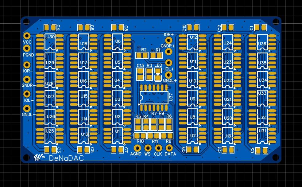
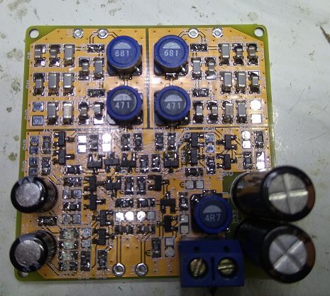
(Below is a board just off for fabrication which parallels 36 DAC chips. Its designed to be stacked for building DACs with outrageous numbers of paralleled chips.)
![]()
-
Going beyond PhiDAC
07/16/2019 at 02:35 • 0 commentsA PM I received from an interested DIYer asked me my view of PhiDAC SE's sound against the original lingDAC. I was piqued too so set up a comparison. The result was that PhiDAC SE won on bass (all those caps in the 'pants' aren't for nothing!) but lingDAC's top-end was still sweeter. So not an outright win for either design. Seeing as lingDAC's power supply is an extremely modest one due to the choice of a 5*5cm form-factor for the PSU board, I wondered whether lingDAC could be improved with the addition of more caps. Turns out it can - so, with a considerably improved PSU, it wasn't a big surprise that lingDAC became the clear winner in the shoot-out.
This result has led me away from using ICs and back to the discrete-based I/V stage of lingDAC for my 'next generation' DAC. I've also decided to introduce a new element into the design, a transformer. In the past I've used transformers for bal-SE conversion (or even just SE-SE isolation) of the output on various prototypes but this time the primary proposition is a little bit different - impedance transformation. Isolation is of course handy to have but here its coming along for the ride.
As with any discrete I/V stage, input impedance is a major design focus. With a filter prior to the I/V as I'm using, the I/V stage doesn't see the high impedance current source output of the DAC, except at the lowest frequencies. Rather it sees the shunt caps of the filter and these have a falling impedance with frequency. The presence of the shunt caps leads to increasing HF distortion whose overall magnitude is related to the ratio of the filter's Zout to the I/V's Zin. Its for the lowest HF distortion that we need the lowest possible Zin for the I/V. Given the I/V stage's input topology is a grounded base transistor, its Zin is a function of the collector (or emitter) current. In other words, higher gm for the transistor is better as then the Re is lower. To get a 1ohm input impedance this necessitates 25mA collector current, which is a bit on the high side - lingDAC operates with single digit mA and has around 5ohm looking into the first transistor's emitter. If the filter were matched to this impedance we'd get a substantial amount of distortion at all frequencies seeing as the input impedance varies with the signal. So I use a degenerating resistor in series with the emitter to give a higher overall input impedance, the variation of the Re with signal then is a smaller fraction of the total input impedance. Still, the HF distortion isn't too pretty being of the order of 1%.In order to aim for lowest distortion it turns out we want the filter to have as high an output impedance as we can, and the I/V to have the lowest Zin. Lower Zin can be obtained through the use of a CFP (complementary feedback pair) - a composite transistor which uses local feedback to give a much lower Re for the same Ic as a single transistor. I've played with CFPs and they're a bit tricky to get stable, particularly when both transistors are bipolars. A bipolar/MOS partnership I've found best from the pov of stability issues. I've already got a re-design in the works of lingDAC using CFPs in the I/V stage, however its only at the PCB layout stage and has been languishing there for months as other avenues have looked more interesting, in particular working on raising the filter output impedance.
To raise the Zout of the filter requires higher valued inductors (together with smaller caps). Larger valued inductors get more tricky to source - physically they end up bigger and most likely SMT versions won't exist. The TDK 7mm range lingDAC uses tops out at 1mH for example which would permit less than a 2-fold increase in Zout of lingDAC's filter. There's a considerable downside to raising the filter impedance and that's that all current output DACs prefer to have their outputs loaded with the lowest possible impedance. An increased filter Zout brings along an increased Zin. So what's good for the DAC is bad for the I/V, and vice-versa. What to do?
This is where the transformer comes along to resolve the dilemma - it offers impedance transformation so that the DAC can have its low impedance load while the I/V can still see a high impedance. In theory, everyone's happy. In practice its not quite so simple but the transformer does bring something genuinely useful to the party. I'll add more details in a subsequent post, time to refresh my cup of black tea....
-
Evolution of PhiDAC to PhiDAC SE
05/04/2019 at 06:20 • 0 commentsA number of kit packs of PhiDAC have been made up and shipped out to interested parties. The first feedback has come from Phuong in Vietnam, he's built a PhiDAC for himself and also made one for a friend, as a gift. Phuong said that at first his friend didn't think too much of the bare PCB but all that changed when he heard the first few notes coming out of it....
I've done some experiments with improving the power supplies to the AD8017s. I've created 'hats' with extra caps on to get low impedance, right at the opamp power pins. With 6 or 8 1800uF Nichicon HZs (the lowest ESR electrolytics I've been able to find) the quality of massed vocals (I listen to quite a lot of choir music) has improved noticeably and overall dynamics are slightly better. These mods though aren't amenable to any kind of volume production nor are they likely to survive boards being shipped anywhere as they rely on soldering for both electrical and mechanical connection. So I figured I needed a more robust way to achieve the depth of power supply impedance I'm looking for.
From building up perhaps a dozen PhiDACs I've encountered almost the full variation in parameters of TDA1387s that the datasheet describes. It thus turns out that in some cases PhiDAC won't operate to spec, the DC offset will be too high and hence will clip the output before digital full-scale is reached. It seems to me the best way to solve this is include a micro which allows the DAC to self-calibrate. While I peruse various manufacturer's sites in choice of the ideal MCU for this I've gone on to develop the 'PhiDAC SE' where the extra PSU capacitors are included on an extra PCB (or three). I've also swapped the opamp from AD8017 to AD815. One reason for this change is I have a number of tubes of the latter which I'd like to put to good use. Another is that I have had some reliability issues with the recycled AD8017s - some have failed, none of the AD815s I've used (I played with them in other projects prior to this which is how I acquired a stock of them) have had an issue although I understand they too are recycled. AD815 has another advantage in that its much more flexible in its power supply requirements - in particular its upper limit is above 30V, a far cry from AD8017's 12V. The package is much larger though and this necessitates a larger PCB.
I've run into some oscillation problems with AD815 which didn't happen with AD8017 but then I'm driving headphones direct now as the AD815's superior thermals render that a practical option. Turns out the ferrite bead at the inverting input might not be the best choice. As a result of the transient oscillations and a couple of small board errors the rev1 board is undergoing re-layout and hopefully will go off for manufacture this week.
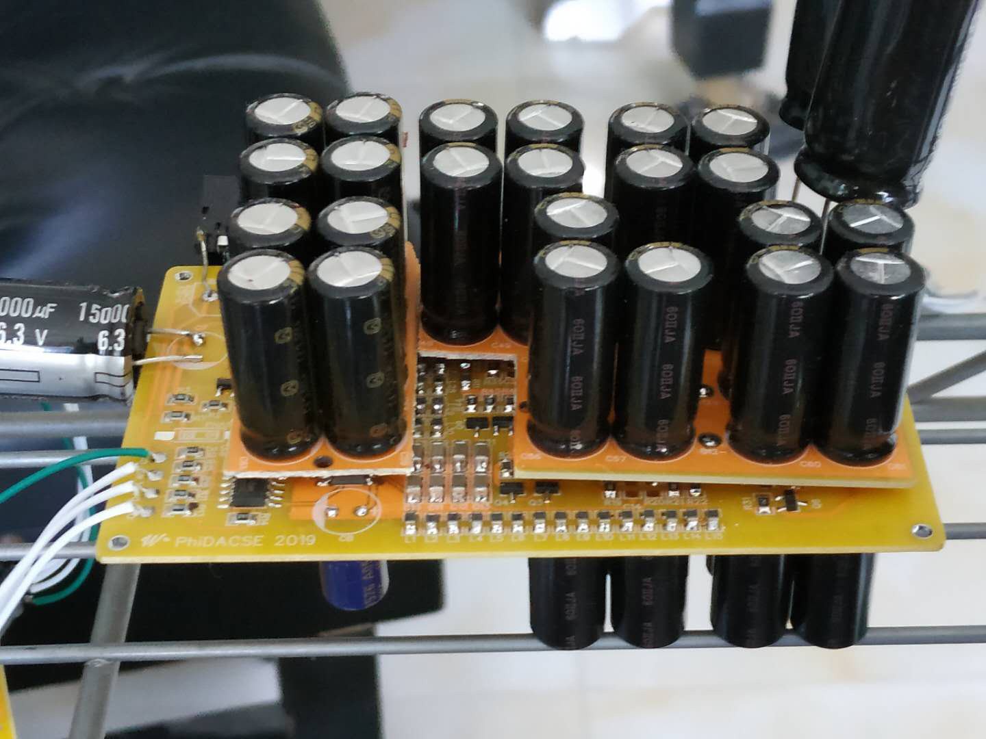
Here's one example PhiDAC SE (an extreme one) where the extra caps have been fitted both to top and bottom of the PCB. While adding one 8-cap PCB per opamp makes a significant difference, the second one may well give no additional improvement. I had to try it though :)
![]()
-
Evolution of 0DAC
01/08/2019 at 06:54 • 0 commentsI built up a few of the 4 board v2 lingDACs and to date one has been sent out to a friend, another is waiting to go. Each took a few hours (in the region of 5-6) of labour - not just in assembling the parts on the PCBs but also in pre-selecting the inductor and capacitor values to get the predicted frequency response out of the filter. Then there's a couple of select-on-test resistors to set the DC offset to mid-span. When I received messages from interested customers many (not all) seemed rather put off by the asking price. So I began to wonder if it might be possible to simplify the design to make it more mass reproducible.
The filter is the foundation of the sound of this DAC - bypass it and you lose much of the 3D effect. But how good does it need to be really to keep the subjective benefits? I played around with reducing the order and found that while the measurements suffer quite badly (the waveform above 5k as shown on a 'scope starts to look decidedly weird) with a 3rd order (single L, 2 Cs) the sound didn't suffer much if at all. So a 3rd order filter would definitely be viable, if only I could find an inductor with close enough tolerance (20% really isn't good enough). Another set of experiments I did using ICs instead of discrete transistors to see if the circuitry could be simplified. As usual with opamps substituted for discrete transistors the power supplies become very critical to the subjective effect, which then means more complexity in regulators. I decided to press on regardless - rather than use regulators I have gone for yet another of the same opamp (AD8017) to create nice quiet, low impedance rails. One huge advantage AD8017 has is its available as pulls on Taobao at a rock-bottom price. The third step is to compress all this onto a single PCB - the result is called PhiDAC.First generation PCB prototype :
![]()
Some good news - for PhiDAC the BOM cost has come down. Using parts sourced from Taobao in sufficient quantities you can acquire all the components for about $3 per DAC, including the PCB. If you prefer to source from Mouser that can be done too but be prepared to pay around $50 for one off (excluding PCB). The AD8017's 'official' price is over $5 and there are 3 per DAC. -
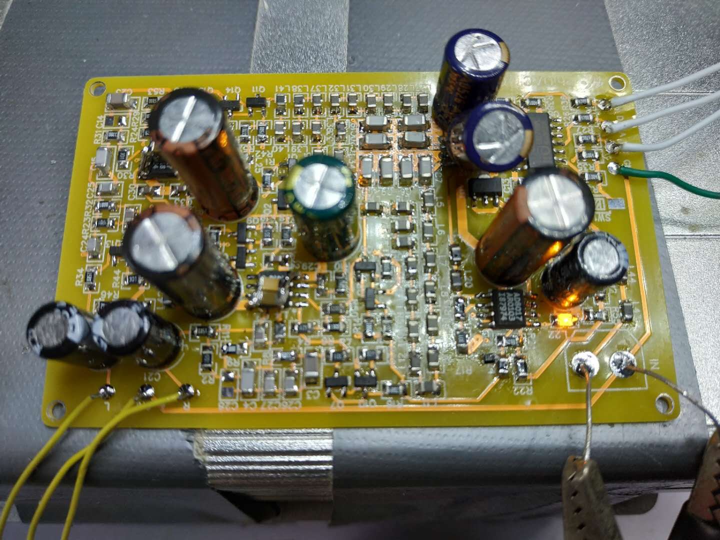
V2 filter I/V board up and running
06/11/2018 at 10:59 • 0 comments![]()
Since the new DAC board reduced the number of DAC chips to two, a new filter-I/V board was called for which was able to run on half the signal current. Here it is - there are a few significant changes :
- Filter inductors are increased in value as now the filter has a higher characteristic impedance (about 50ohms)
- Capacitors which were X7R have been replaced by NP0 - increasing the filter impedance has made this practical. The main advantage of using NP0s is their closer tolerance and much better stability, meaning the filter build no longer needs a long time fiddling to get the right cap values.
- This board runs on 9V which means it can now deliver the industry standard 2VRMS DAC output signal, if desired. Although the supply voltage has gone up 50%, the current draw has gone down so this board consumes less power.
- The I/V stage is a bit more complex but the new circuit has better compatibility with alternative DAC chips. I plan to try this with the TDA1387 but powered from 3V (rather than 6V as at present) which wasn't practical with the first generation board.
- It sounds a little bit better too - there's slightly more detachment of the images from the speakers.
- The BOM cost has gone up (NP0s being dearer than X7Rs) but OTOH the build time has gone down markedly.
-
DAC v2 board arrives
05/10/2018 at 06:10 • 1 commentThe original 4* DAC board came with a few errors, the biggie was that I'd overlooked how noisy the TL431 is and used it as reference for a series regulator without any low-pass filtering. The result was that with the original PSU configuration there was an excess of hiss. I bodged the boards to include an additional RC stage between the TL431 and the pass transistor which made the boards usable.
On giving more attention to the PSU I played around on the bench with a Sziklai pair of transistors rather than a single emitter follower. Turns out this combo is rather prone to oscillations (above 10MHz) but I managed to get it tame by using a bipolar/MOSFET combination. The advantage is the pair of trannies wrapped around one another gives a much lower output impedance, something very desirable in a power supply reg for audio use. The CFP/Sziklai pair has been put to good use in the new updated PSU on v2 and I was quite surprised how much of an improvement to the bass it has brought. In fact I arrogantly consider my DAC to have the best bass of any DAC I've ever heard (bear in mind I've not heard that many, but did have a listen to a few at a recent high-end show in Shanghai). The improved bass gives the subjective impression of more 'weight' or 'authority' to piano for example, but also contributes to a much more believable rendering of the recorded acoustic.
The last change is the reduction from 4 DACs to 2, a corollary of the improvement to the PSU. Using fewer DACs means changes are needed to the filter-I/V board, but these are entirely component value changes (inductor values go up, caps go down). The 2 DACs are permanently wired in anti-phase to maintain PSU stability. The TDA1387 takes a varying current from the supply depending on its digital code, however two DACs together fed in anti-phase take an almost constant current. This is quite easily visible by looking at the modulation of the supply when playing music, via a fairly sensitive preamp as found in my millivoltmeter.
![]()
We've adopted a 3 island ground fill, the areas are the input buffer, the DACs themselves and the PSU (which is top right). The 2 yellow and one red LED take over the function that was previously given to the second TL431.
Audiophile-sounding DAC for almost no money
0DAC - delivers engaging, immersive sound with a pricetag at least two orders of magnitude from commercial audiophile DACs