Close
0%
0%

Magic Frame : Turn Everything into a Touch Area

Build your own touch screen solution adapted on your TV by using some CIS or CCD sensors from old scanners

Similar projects worth following
This tutorial is about helping people to build their own touch screen solution based on any flat screen TV. It uses light triangulation technology to read the coordinates. This method is quite cheap ( the priciest part is the TV), with a good quality image and you can make the table almost as small and as thin as your TV is.

Of course, nothing is perfect and with this solution it's probably not possible to build a 100% multi-touch screen and it's hard to cover the entire screen area. But depending on the way you make it you can have some interesting results. Plus, I am sure there are a lot of possibilities I haven't thought about to improve this. ;-)

This solution implies the use of light triangulation to read a very precise coordinate. Basically, it's like having a huge number of IR receptors with some IR LED. You turn on every LED one by one and read the sensors. When one receptor can't see any light, it means that an object is blocking the light. With enough LED and sensors you can get a much more precise solution.

But for this project, I was looking for something more suited for the reading. A CIS sensor, is in most scanner. In those devices, it's basically a black and white camera which reads only one line of pixels. To scan a color document, a RGB LED blink in the three colors and the CIS reads all of them for every line of the document. Then it can calculate the exact colors depending of the Red Green and Blue reaction.

Using a CIS sensor gives you access to 2700 light sensors on a 20cm line. Most people who take sensors and actuators from an old printer/scanners only take the RGB LED and the light conductor from this part, as we can see here. If you like recycling, you could examine the possibilities of CIS. Not having found many DIY projects on the internet using them, there are probably a lot of different ways with which you could use these sensors! In this tutorial I will also explain how to hack your own scanner.

For this touch table, I used one CIS sensor with 24 IR LEDs. The object is detected on a 740x380mm surface by a Teensy board (which works under Arduino environnement). This board turns the IR LED ON, reads the CIS and calculates the exact position of an object. Then it sends the coordinates as a mouse, a keyboard, a Python program or just as Serial on a Raspberry Pi which shows the interface through the HDMI on a 32" TV screen.

FS09ODPIM53Q3N8.ai

Vectorial Link illustration

postscript - 1.12 MB - 09/05/2017 at 18:24

Download

Touch Table Python.zip

Serial software to communicate with the python interface

Zip Archive - 299.89 kB - 09/05/2017 at 18:24

Download

FVTD63XIM53Q3M7.ai

Vectorial Toad illustration

postscript - 196.90 kB - 09/05/2017 at 18:24

Download

CCD_Arduino_Processing_Color.zip

This Processing program shows 20 different cluster of the CCD sensor. If the average analog value of the zone is close to 1024, the cluster is white. If it is lower it gets darker

Zip Archive - 7.56 kB - 09/05/2017 at 18:24

Download

Touch_Table_Final_V7.zip

Final code for Teensy board

Zip Archive - 5.55 kB - 09/05/2017 at 18:24

Download

View all 7 files

  • 1 × Raspberry Pi
  • 1 × Teensy 3.X
  • 1 × CIS sensor From a scanner
  • 20 × Led IR
  • 1 × TV Any type

View all 6 components

  • Magic Frame V3 is ready !

    jean.perardel10/21/2017 at 12:32 0 comments

    The Magic Frame V3 is now printed and assembled. 

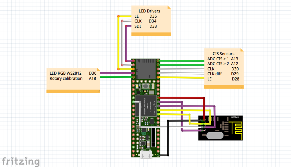
    The 3D design has now 8 LED row per piece of 13cm. Each row has 3 LED so 24 LED per piece. Which is 32 * 3 = 96 LED for a 52cm frame. 

    Here is the schematic : 

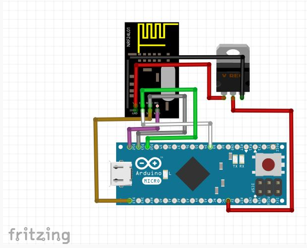
    And the schematic of the Bluetooth / HID central 

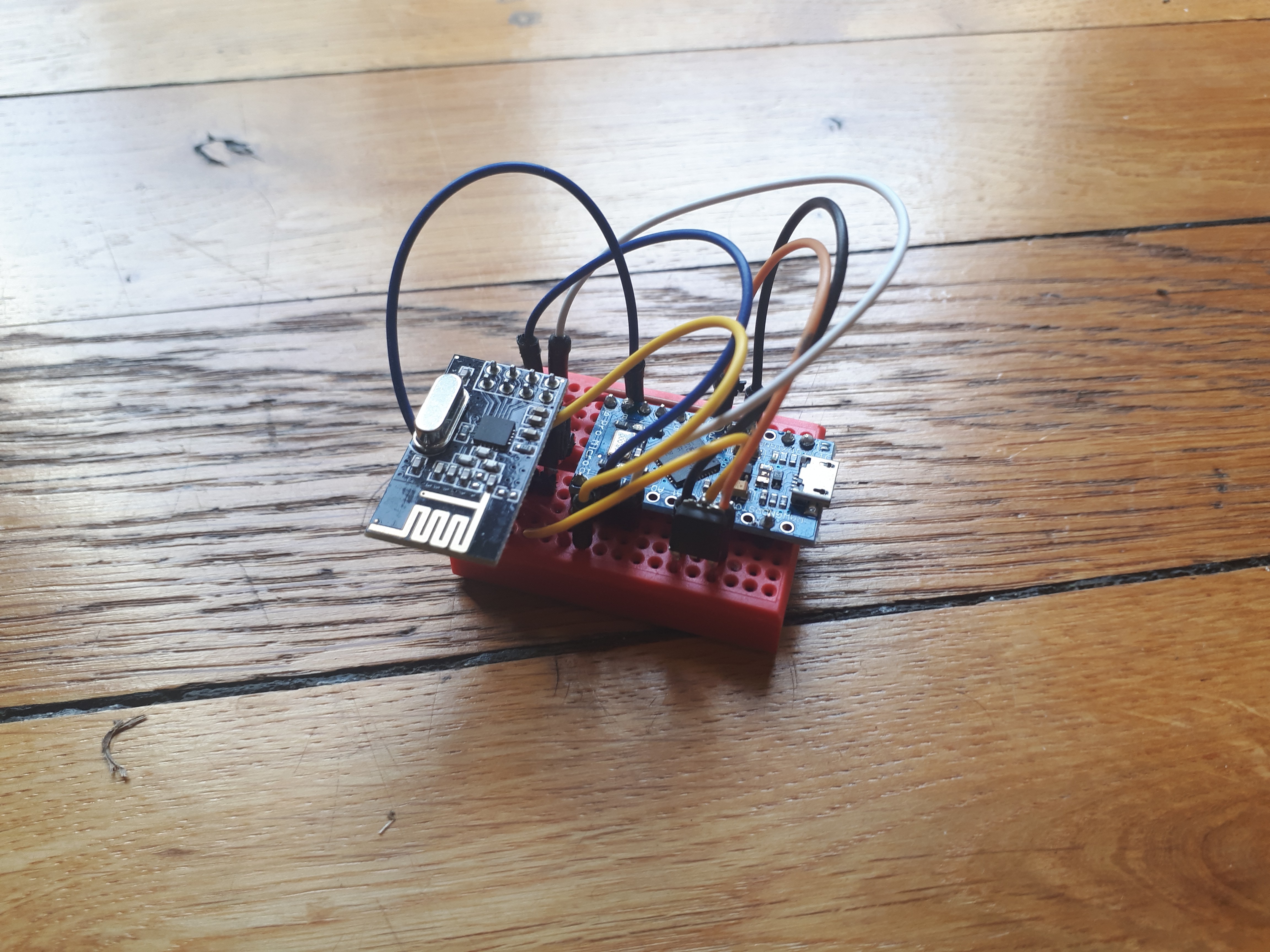
    I didn't had much time to solder it and build a 3D printed box. This will be for later ^^

  • Now wireless with Bluetooth and Lipo Battery

    jean.perardel10/16/2017 at 21:07 0 comments

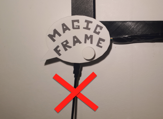
    It's nice to have frame on your wall with a photo or painting. But to be really discret and easy to integrate, we don't want to have a black wire going away from it.

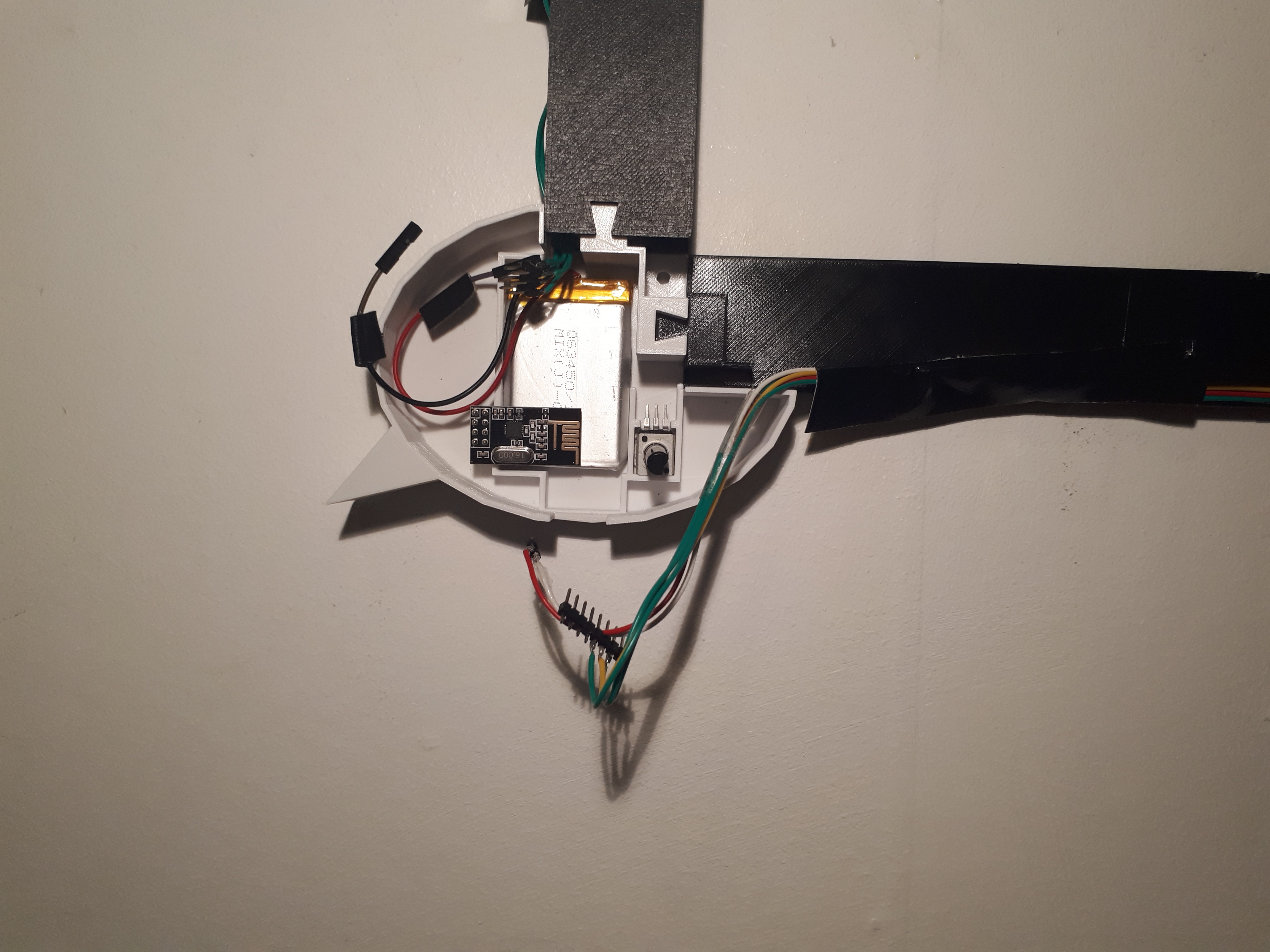
    The new version of the frame now embed a 1000 mA Lipo Battery and a NRF24L01+ multi-pair bluetooth module. Now,  we can get rid of the annoying micro USB cable!

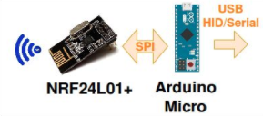
    The reception is made by an Atmega32u4 board wired to a computer with a USB port. 

    The particularity of the Atmega32u4 on the Arduino Micro board is to be able to act as an USB HID device and/or a serial port. This mean we can send some Keyboard keys, mouse position or CDC serial data. 
    The original program of the Magic Frame on the Teensy board also gave the possibility to act like a HID or CDC, but now we can also do it wirelessly ;-)

  • Magic Frame V2 printed and wall mounted

    jean.perardel10/16/2017 at 18:50 0 comments

    A lot of printing hours later....

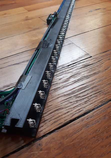
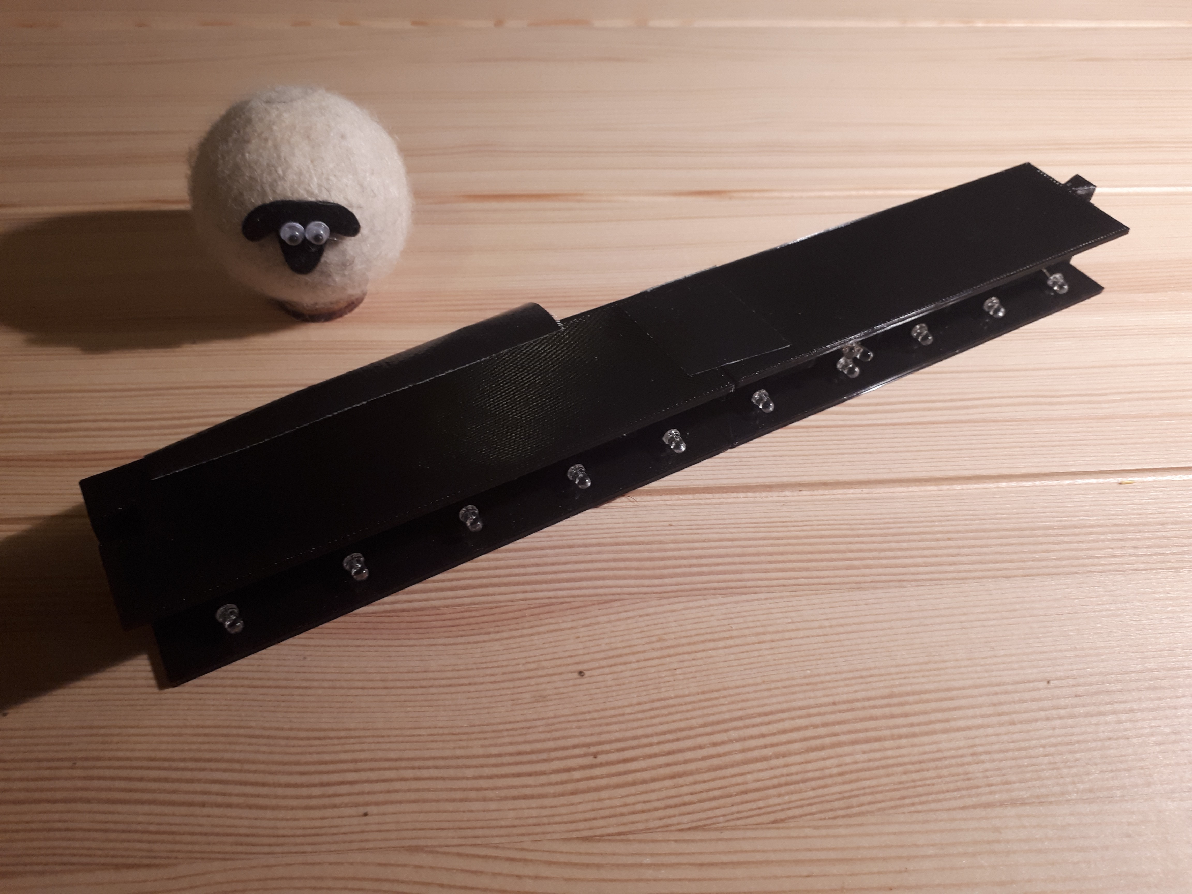
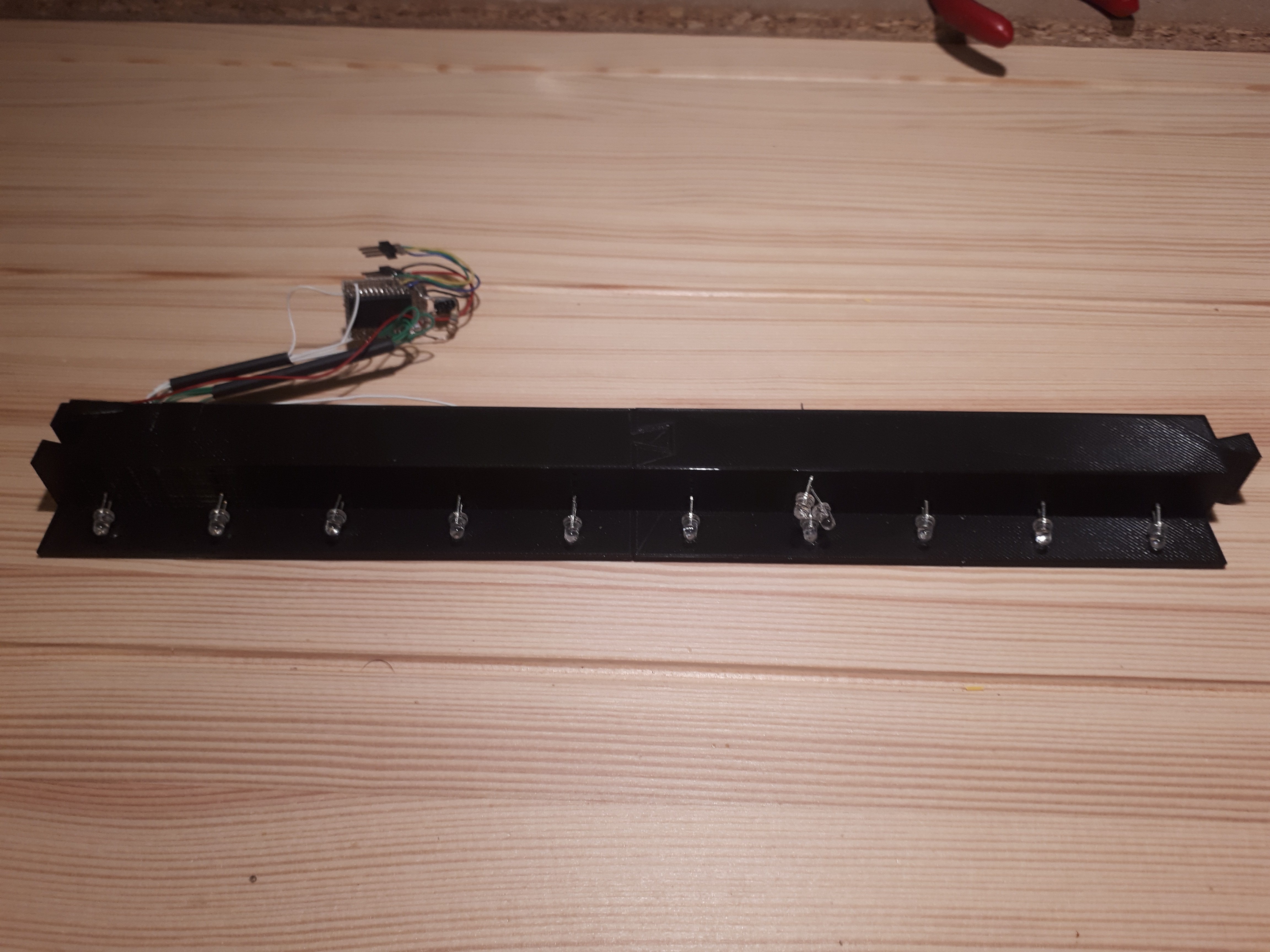
    Here are 2 of my LED frame elements plugged in. I added the IR LED and the driving circuit. 

    I only added 1 LED per line (except on the seventh one, there are 3) because it's enough for the first frame size I want to build. 

    I also drew a roof for the element to hide the wires and circuit. 

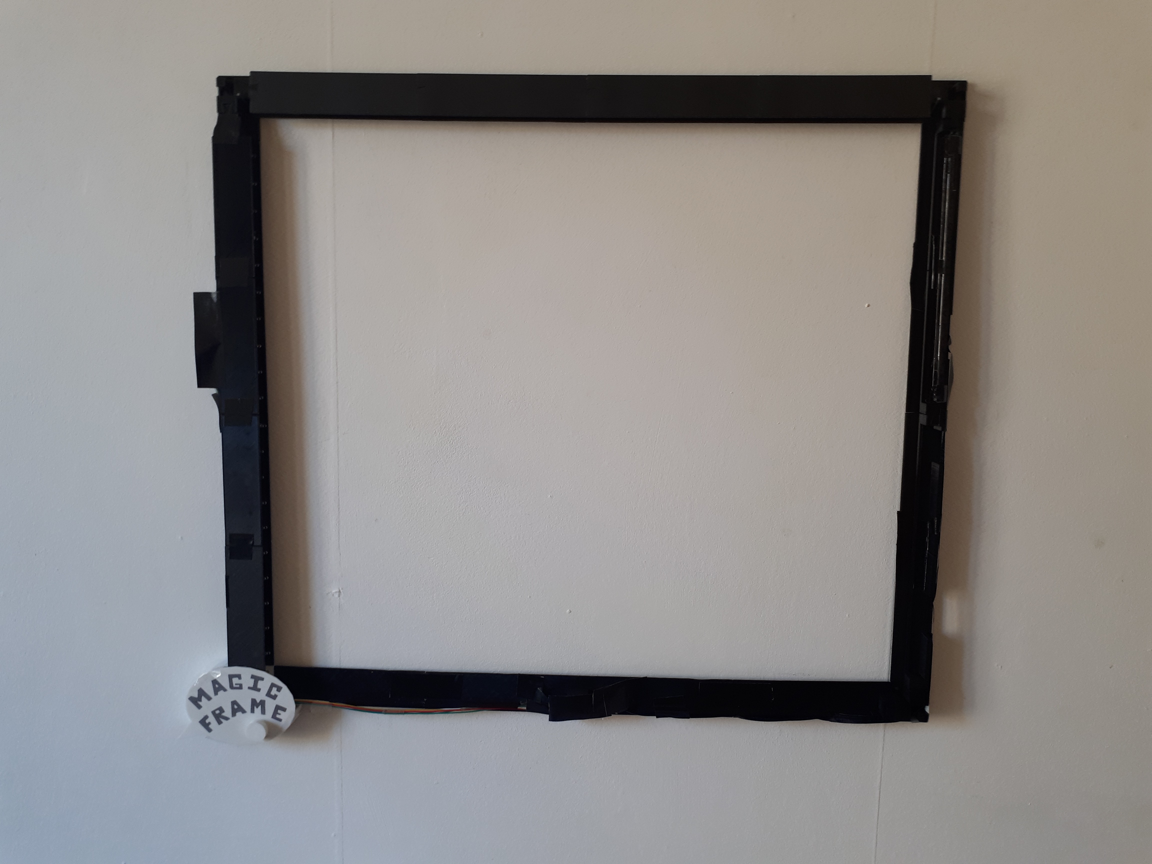
    And now, the frame complete. There are actually only 4 elements at the top and bottom, but they are a bit larger. 

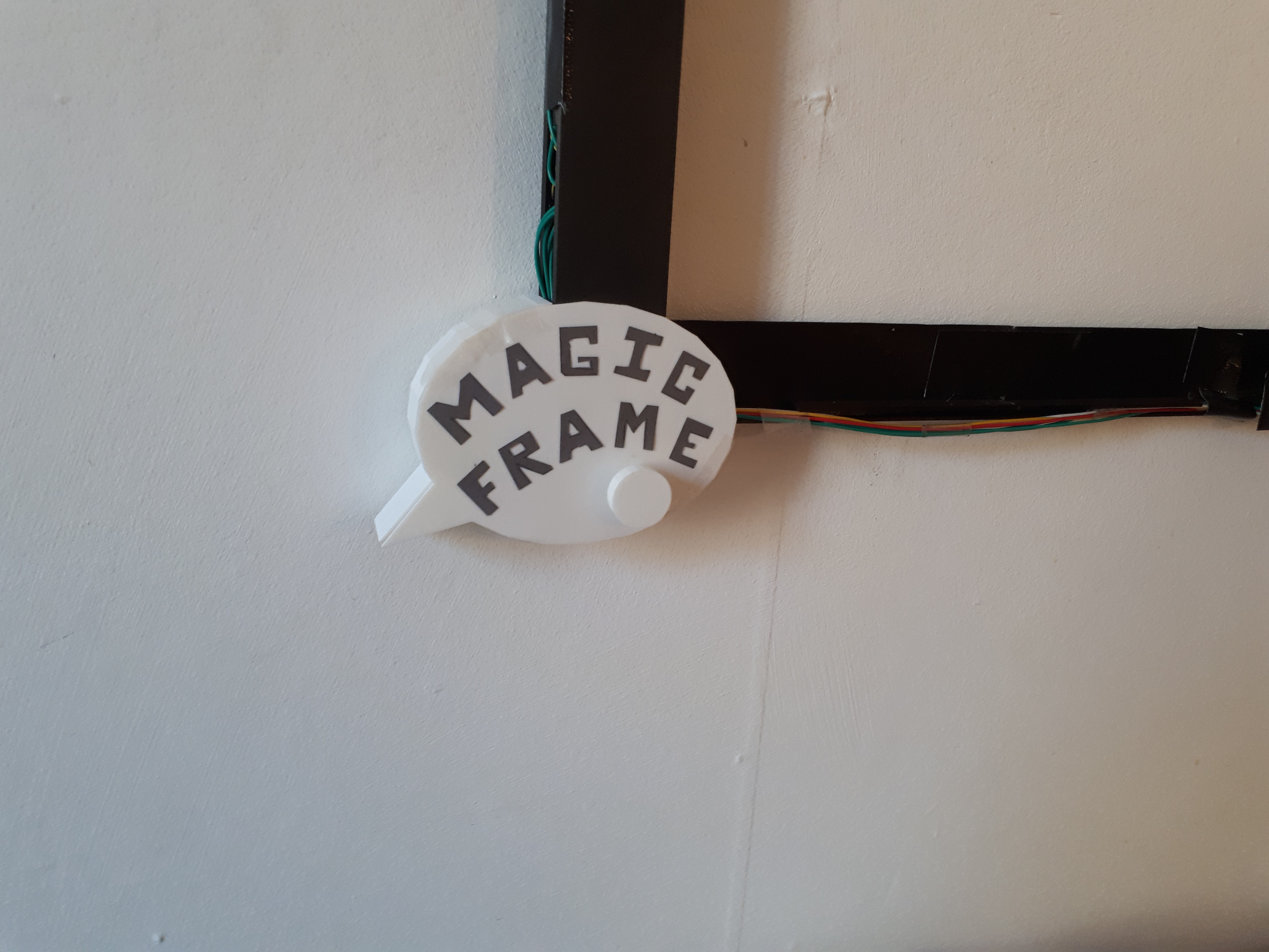
    We can see the round rotary button under the word frame. You can increase or reduce the CIS's sensitivity with it.

    I am really sorry... This assembly is a mess! 

    That's one of the reasons why I've I immediately started to drawing a Magic Frame V3   :-p  

  • Magic Frame V2

    jean.perardel10/16/2017 at 17:59 0 comments

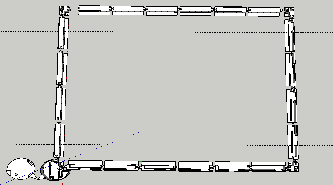
    The idea is to build an adaptable frame inspired by a jigsaw puzzle. Any size screen can be made just by adding more elements and by increasing the infrared LED power. 

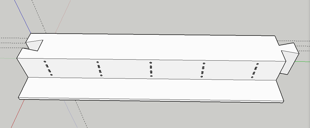
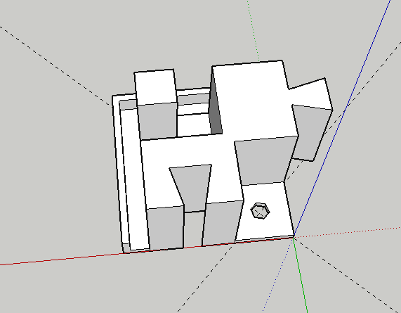
    Here we have a "LED element" ready for 3D print. Several elements can be plugged into each other to create two emitting frames. The 5 small holes lines are for the LEDs. You can fit 3 LED per line to increase the emitting angle and the power. So this element can have 15 LED in total but it's only a 5 LED detection. 

    Here is a CIS element. As it's 26cm (10.2inch) large, It's printed in two parts to fit into an Ultimaker 2. 

    The corner of the frame to hold the structure and insert a screw for a wall mounted use. 

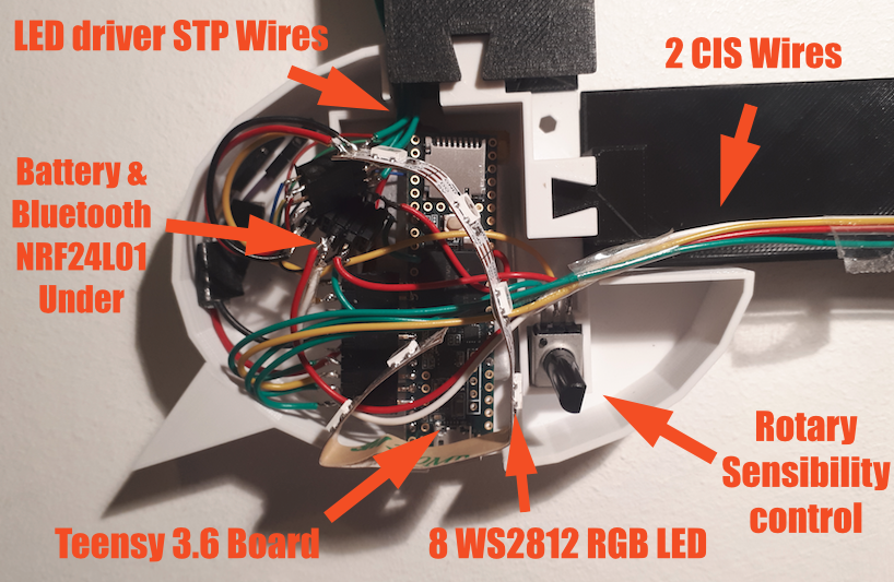
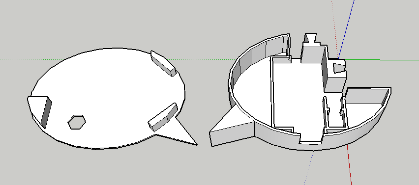
    The last corner integrates the control board with most of the elements : 

    •  A battery for wireless autonomous application
    • The Teensy 3.6 control board
    • A rotary going through the hole. It controls the sensitivity of the CIS sensor. 
    • 6 WS2812 RGB LED. As this element is printed in white. The LED gives a color to all of the enclosure. It will also help with calibrating. 

    Here is the frame with all the elements. At left and at the top, we have 10 LED elements so 50 LED. At the bottom and on the right we have 6 CIS sensors. 

    This will make an almost perfect multitouch screen! 

  • Video of my new hacked CIS sensor ^^

    jean.perardel10/15/2017 at 23:00 0 comments

    As I was saying on my last log, here is the video of the CB376-67901 I hacked. It took me a while, because there isn't any information about it on the internet... 

    Now lets add it to the touch frame!

  • New CIS sensors bought on internet, let's HACK!

    jean.perardel10/15/2017 at 13:01 13 comments

    As I was saying in a previous post, I bought some CIS sensors on Ebay. 

    I have already hacked several sensors I found directly in old scanners, but this method is really time consuming... and you never really know what kind of sensors you will find!

    So I wanted to find a more "generic" CIS sensor, and this wasn't easy... I ended up buying on Ebay some sensors with the wrong references and no datasheet. 

    When I received them, it was the start of a very long day...

    I started with some internet research, all the videos and blogs with people playing with CIS sensors (on their oscilloscopes most of the time). I couldn't find any information about those references.

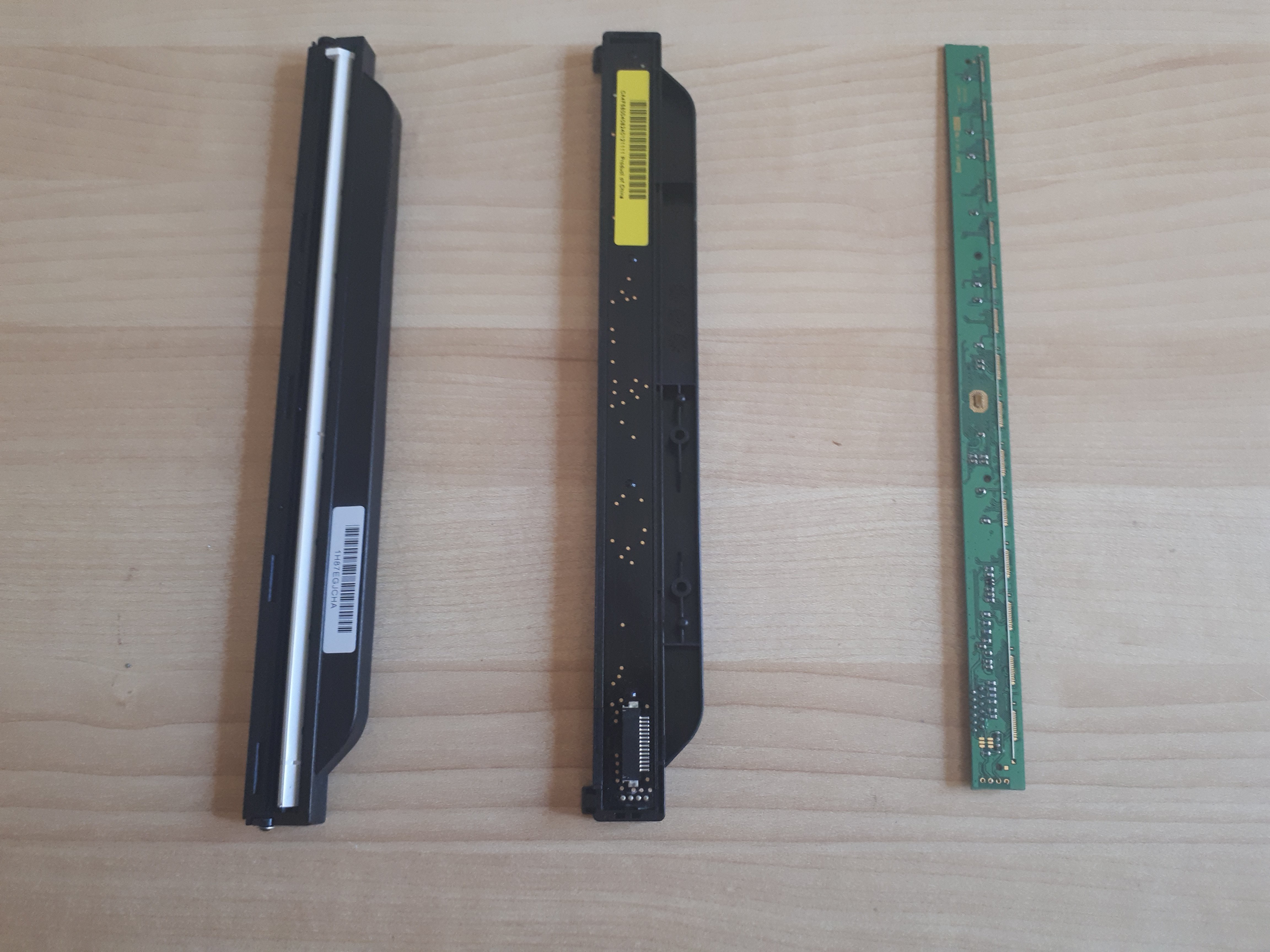
    From left to right : CIS front sensor with a cover, CIS back sensor with a cover, CIS front sensor without a cover

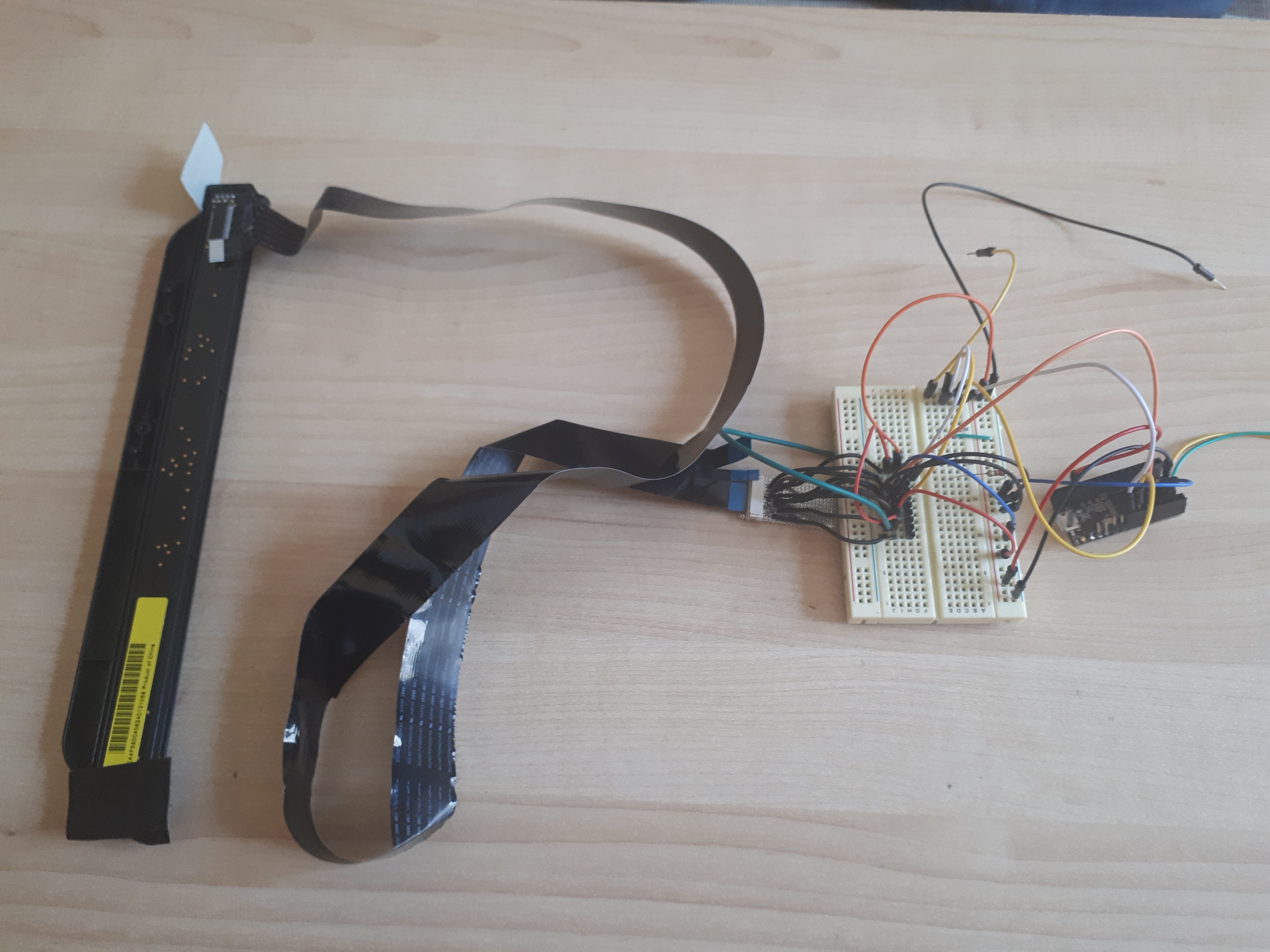
    I started with the CB376-67901. I bought two of them, so I removed the circuit of the first one to have a better visual access to the lines. This sensor has 14 lines and you need a flat flex scanner cable (you find some in every scanner) and a ZIF connector to build an interface board more easily.  

    From left to right : CIS sensor, Flex cable, ZIF connector interface board, breadboard interface, Teensy 3.2.

    I was able to identify :

    • GND on Pin 6 and 8, 
    • LED pins on Pin 11 to 14 
    • VCC on Pin 2 and 10. 

    That's a good start, but still 6 Pin left for the : 

    • Analog output
    • Clock
    • Latch
    • Differential lines? 
    • Maybe others if the protocol is different... 

    Then, I compared them with some CIS I used to hack and I discovered that CIS from the brand HP had the same Pin so far. Interesting! But at that time (2 years ago!) I couldn't make it work... Here is the informations I had : 

    • Analog output on Pin 1
    • Latch on Pin 5
    • Clock on Pin 9
    • Still no idea for the other lines

    Second step, I found an old HP scanner and opened it. And this was an amazing moment : the same plastic package, and it looked as throught it was the same Pin from the one I had so far!! 

    So I wired my CB376 CIS sensor directly into the flex connector of the mother board, and I could see the outputs of the CIS on line 1. 

    Here is the exact configuration : 

    • 1 Analog output 
    • 2 VCC (5 volts, but works with 3.3)
    • 3 VCC 3.3 volts
    • 4 GND
    • 5 Latch
    • 6 GND
    • 7 differential signal (opposite to the clock)
    • 8 GND
    • 9 Clock
    • 10 VCC
    • 11 - 14 RGB LED

    A few lines of code on the Teensy board, and now you have a new sensor to play with!!

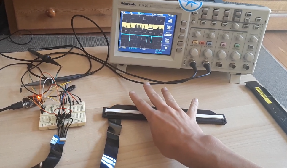
    The blue signal is the Latch (to help to synchronize), the yellow signal is the analog output. You can see 4 rounded peaks very close to each other, on the yellow signal, it's my 4 fingers.  ^^ I ll upload a video soon! 

    I actually damaged one one of the two CB376, some pixels don't work anymore... But I still have one more sensor, and also the possibility to order more! 

    I haven't yet succeed at hacking the CE-841. Here is what I can say about it so far : 

    • 2 GND
    • 5 GND
    • 8 GND
    • 14 LED

    I need to work a bit more on this. I ll keep you posted! ;-)

  • Too many LED, lets add a driver!

    jean.perardel10/15/2017 at 11:11 0 comments

    I am currently working on a new frame to make the project more adaptable. As I don't want to have too many wires to solder on my Teensy board. It's probably now time to move to LED drivers. 

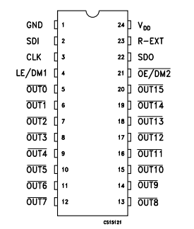
    Several years ago, as I was building some LED Cubes, I used to play a lot with STP16CP05 a lot. 

    Those driver are very easy to use and program. Moreover, they can drive 16 outputs and you can add as many STP as you want in serial (exactly like the WS2812 RGB LED system). 

    To make it work, 

    • add VCC (3.3 or 5V) and a ground with a 10uF capa between them. 
    • Set the OE/DM2 to ground
    • Add a resistor between R-EXT and the ground (the value depends on the output current you want, see the datasheet) 
    • And wire the SDI, CLK and LE signal to your control board. 
    • To add a second driver wire the SDO to the SDI of the second one!

    You can find a test code on the GIT of the project. 

  • Increase the system speed by x2.5 with a Teensy 3.6

    jean.perardel10/15/2017 at 10:58 0 comments

    I received a Teensy 3.6 this week to replace the 3.2 I was using. I have to say, Paul Stroffregen has done an amazing job again! 

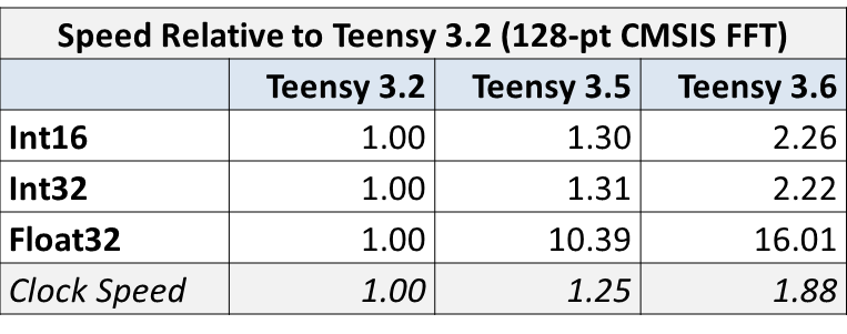
    The package, is maybe a little too big, as the board has a micro SD slot embedded in it and many IO. But here are some comparison from the website OpenAudio.

    It's not on this list, but the Teensy 3.6 can be overclocked at 240MHz which makes it two and half times faster than the Teensy 3.2 I was using. I can easily double the number of LED or read twice as many pixels and still be more reactive! :-) 

  • CIS or CCD ?

    jean.perardel10/04/2017 at 14:43 0 comments

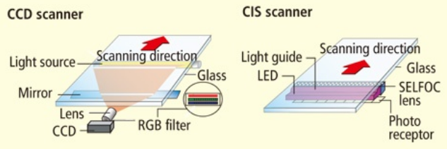
    There are two types of sensor in a scanner. The one I mainly used is actually a CIS (Contact Imaging Sensor) and not a CCD (Charged Coupled Device). You can either, but CCDs are really small. To cover a large screen, it's easier to use a CIS. 

    I've actually mistaken CCD and CIS on the video, I will change it soon...

    I ordered several CIS sensors from "ON SEMICONDUCTOR" on Ebay :

    -> The CE841-60111 which has 1728 sensors on 232mm

    -> The CB376-67901 which has 2048 sensors on 272mm

    If they work well, it's going to be a good start for building a screen frame. 

    This website is really insterresting in helping you  understand the differences.

  • New video is online!

    jean.perardel09/27/2017 at 21:03 0 comments

    I've just finished my new video!! Hard work... ^^ 

    It explains everything you need to know to understand the project. I tried to make it as funny as possible :p

View all 11 project logs

  • 1
    Part list


    When I am working on a project, I like to build things that are the most cost efficient possible but still of good quality. So even those on a tight budget can afford to build their own. It's hard to give the exact amount of money spent, as many things are second hand or from the tip. Here is an approximation :

    Electronic :

    • Raspberry Pi (41$). I built my project with a Pi 2, but the B+ should also be fast enough.
    • Teensy 3.X (20$). I love building projects with my Arduino UNO. But the specifications of this tiny Teensy board are really crazy! (32 bits cortex M4, 72MHz, 256K Flash, 64K RAM, 34 digital PIN...). I think it's very useful to keep one at home. If one of your projects needs more PIN, more memory, more speed or just needs to be smaller, you can easily switch as it's fully Arduino compatible! Just install the Arduino plug-in and keep developing! The only little thing you have to be careful of is the access to the button to reprogram. I had to wire an external button when the table was built and I still needed to calibrate and debug.
    • The CIS sensor. You can easily get one from any old scanners which can be found everywhere. Or buy one on Ebay...
    • LED IR (0.1$). I used some 950nm.
    • The TV. It's hard to give a price, mine is a LG 32" that I bought second hand for 80$.
    • Wire
    • resistor
    • Computer Fan. You can find some in most old computers, you don't need to buy one.

    Some parts can be a bit difficult to solder, I recommend having a good soldering iron. At home I have been using a WS81 from Weller. A bit expensive to buy but it's precise and you can keep it for 20 years ;-)

    The wooden box and table :

    This part is gonna depend on your TV screen. This is for my 32" LG TV :

    The TV box :

    • 2 panels of MDF wood 10mm for the sides : 140 x 845mm
    • 2 panels of MDF wood 10mm for the sides : 140 x 560mm
    • 1 panel of MDF wood 10mm for the top : 950 x 650mm
    • 1 panel of MDF wood 3mm above the top : 950 x 650mm
    • 1 panel of Pine wood 18mm under the TV : 825 x 560mm
    • 2 large Framing lumber supporting the TV : 37 x 54mm (300mm long)
    • Small Framing lumber to ease the screw 15 x 20mm
    • Screws

    The Table under :

    • 1 panel of MDF wood 18mm for the top of table : 670 x 350mm
    • 1 panel of MDF wood 10mm for the layer under the table : 670 x 350mm
    • A very large framing lumber for the table's feet 37 x 54mm, 280mm long(2 for each feet)
    • Screws

    Approximate cost of the wood 70$

    I also used a Trotec laser cutting machine to engrave some characters on it and to cut several small parts of the wood. You can rent it for 25$ an hour from the Fablab next to my place. As I often help them on electronic projects I can sometime have it for free :-)

    Touch detection :

    • 1 Plexiglass 5mm for the support : 750 x 460mm
    • 2 Plexiglass 2.5mm, 735 x 12mm
    • 1 Plexiglass 2.5mm, 430 x 12mm (protecting the sensor)
    • 1 Plexiglass 5mm, 430 x 12mm (with the LED on it)
    • 8 mirrors 150 x 15mm (approximately as it's hand cut)
    • To create a IR lighting paper filter I combined a 106 primary red paper filter with a 181 congo blue paper filter
    • black masking tape
  • 2
    CIS Reverse engineering Part 1


    As Wikipedia is way better than me on explaining :

    "Contact image sensors (CIS) are image sensors used in flatbed scanners almost in direct contact with the object to be scanned. Charge-coupled devices (CCDs), often used for this application, use mirrors to bounce light to a stationary sensor. CISs are much smaller than CCDs, use typically a tenth as much power, and are particularly suitable for low power and portable applications, often powered over USB.[1]

    A CIS typically consists of a linear array of detectors, covered by focusing lenses and flanked by red, green, and blue LEDs for illumination. The use of LEDs allows the CIS to be highly power efficient, allowing scanners to be powered through the minimal line voltage supplied via a USB connection. CIS devices typically produce lower image quality compared to CCD devices; in particular, the depth of field is greatly limited, which poses a problem for material that is not perfectly flat. However, a CIS contact sensor is smaller and lighter than a CCD line sensor, and allows all the necessary optical elements to be included in a compact module, thus helping to simplify the inner structure of the scanner. With a CIS contact sensor, the scanner can be portable, with a height of only around 30 mm. CIS is both a key component of, and widely used in, scanners (especially portable scanners), electrographs, bar code readers and optical identification technology."

    Basically, the CIS you find in a scanner doesn't read lights in two dimensions, but on one line. With the one I tried, there are 2700 different light detectors that we can use as 2700 pixels on a X position.

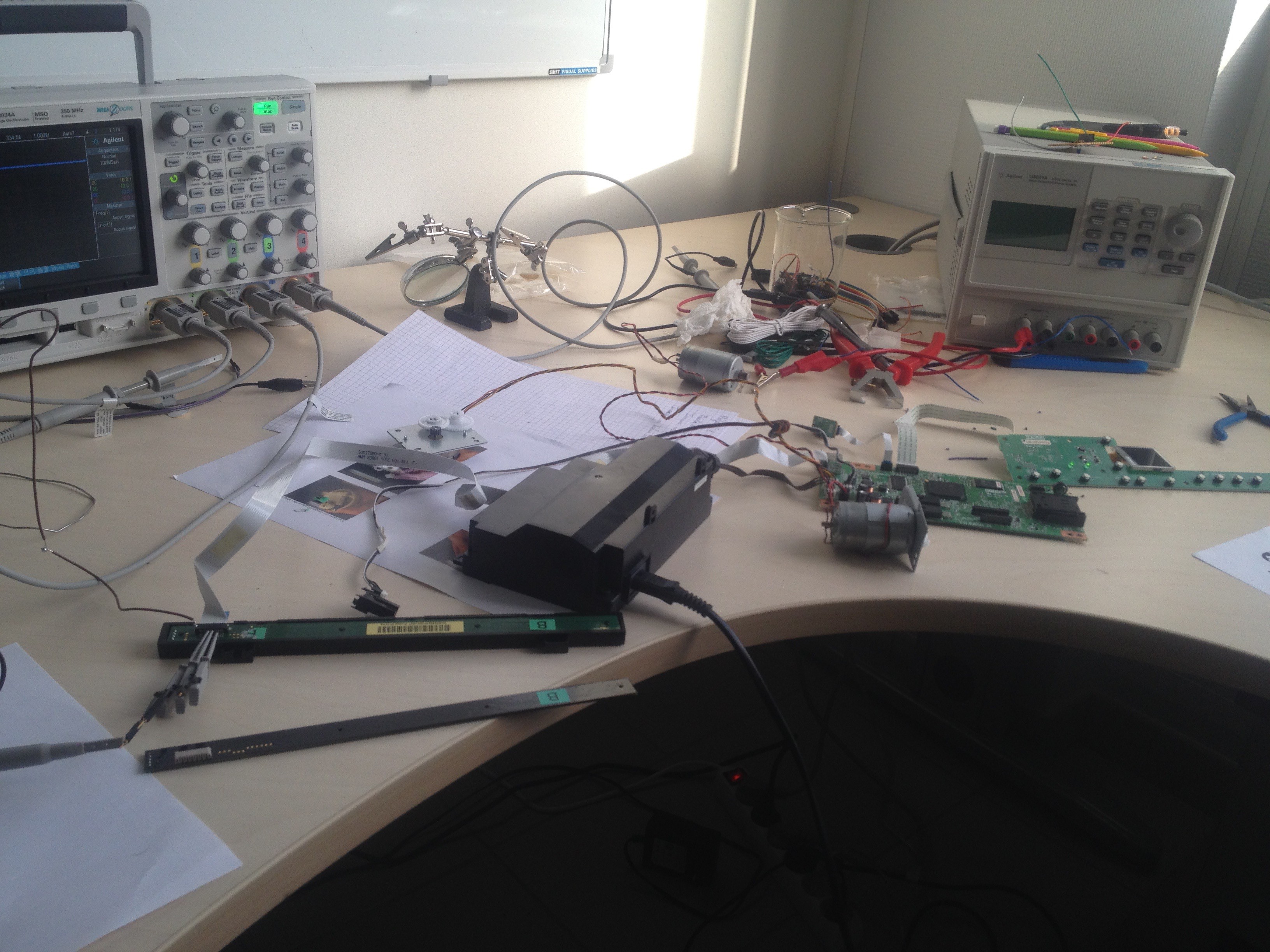
    As I couldn't find any tutorials explaining how they work on the internet, I tried to understand the logic by myself. I started by taking a printer scanner from the trash and opening it. Please be very careful with these devices, they use 220V! Don't do it if you are not sure of what you are doing. Always manipulate them when it's not plugged in and isolate any high power part.

    By visually checking all the lines going from the control board to the CIS you can try to identify the 4 lines controlling the RGB LED, they are generally located at the extremity of the CIS board. With a multimeter, you can check where those lines are going on the communication flex.

    Then you can check if some lines are bigger than others (it's probably going to be the power and the ground, you can verify which one it is with your oscilloscope when the power is ON). Plug an oscilloscope between the other lines and the ground to understand what they are doing.

    I tried two CIS sensors from different brands and they where both using the same communication protocol but not on the same "line order on the flex". When I turned the scanner ON, I could see some data passing. It means that the device was probably testing the sensor when it is turned ON.

    - One line was giving a perfect square signal, I deduced that it was a signal clock.

    - One signal was turning ON and OFF at the beginning of the clock transmission, it's the Latch signal

    - one signal was sending a lot of analog value. Those values changed when my hand was next to the sensor. It is the values from the CIS.

    So I made a test program the on a Arduino UNO board. You can download it at the end with the project.

    With this, you can read on the serial port 16 average values (I call them pixels) of 168 light sensor on the sensor, so almost the 2700 total. Just plug in the lines as explained at the beginning of the above file on any Arduino board and read the data on the serial monitor.

  • 3
    CIS Reverse engineering Part 2


    Last week, I was trying to find some solutions to improve the cover of the detection area. To do this, I wanted to have a second sensor to test new configurations and speed. So I went back to the tip and I took several printer/scanner from different brands.

    I was a bit frustrating to discover that some scanner have a different kind of sensor. No need to open the entire device, they are pretty easy to recognize, as the black plastic package is way bigger (picture 1). Inside, they have a way more complex mirror architecture, a lens and... a very tiny sensor: A CCD! I will try to hack those one to see the possibilities soon, but for now, I needed another "normal" 22cm CIS. So I moved on!

    Second printer I opened was from EP*** brand (Picture 2). The flex connection had 12 lines on 5V :

    • 1 Analog OUTPUT to 4 are big lines easy to identify for the LED
    • 2 (large) VCC? 5 (large) seem to be VCC
    • 3 GND 6 GND
    • 4 (thin) has a square signal with a 100ns period, the clock!
    • 5 (thin) has a short square signal every 20us.
    • 6 (thin) has a short square signal every 20us, another latch?? the latch.
    • 7 (GND)
    • 8 VCC
    • 9-12 RGB LED

    After few hours of test, I couldn't find the good protocol to have the OUTPUT response. Even when the CIS was plugged in the scanner, the analog wasn't giving any clear response (on startup test as the printer was then reporting an error).

    So I moved on to a third printer from H* brand. The flex had 14 lines on 3.3V :

    • 1 The analog
    • 2 VCC
    • 3 GND but not linked directly to the other GND
    • 4 VCC but not linked directly to the other VCC
    • 5 A latch every 40us
    • 6 GND
    • 7 ?
    • 8 GND
    • 9 CLK (clocking every 500ns)
    • 10 VCC
    • 11 - 14 RGB LED

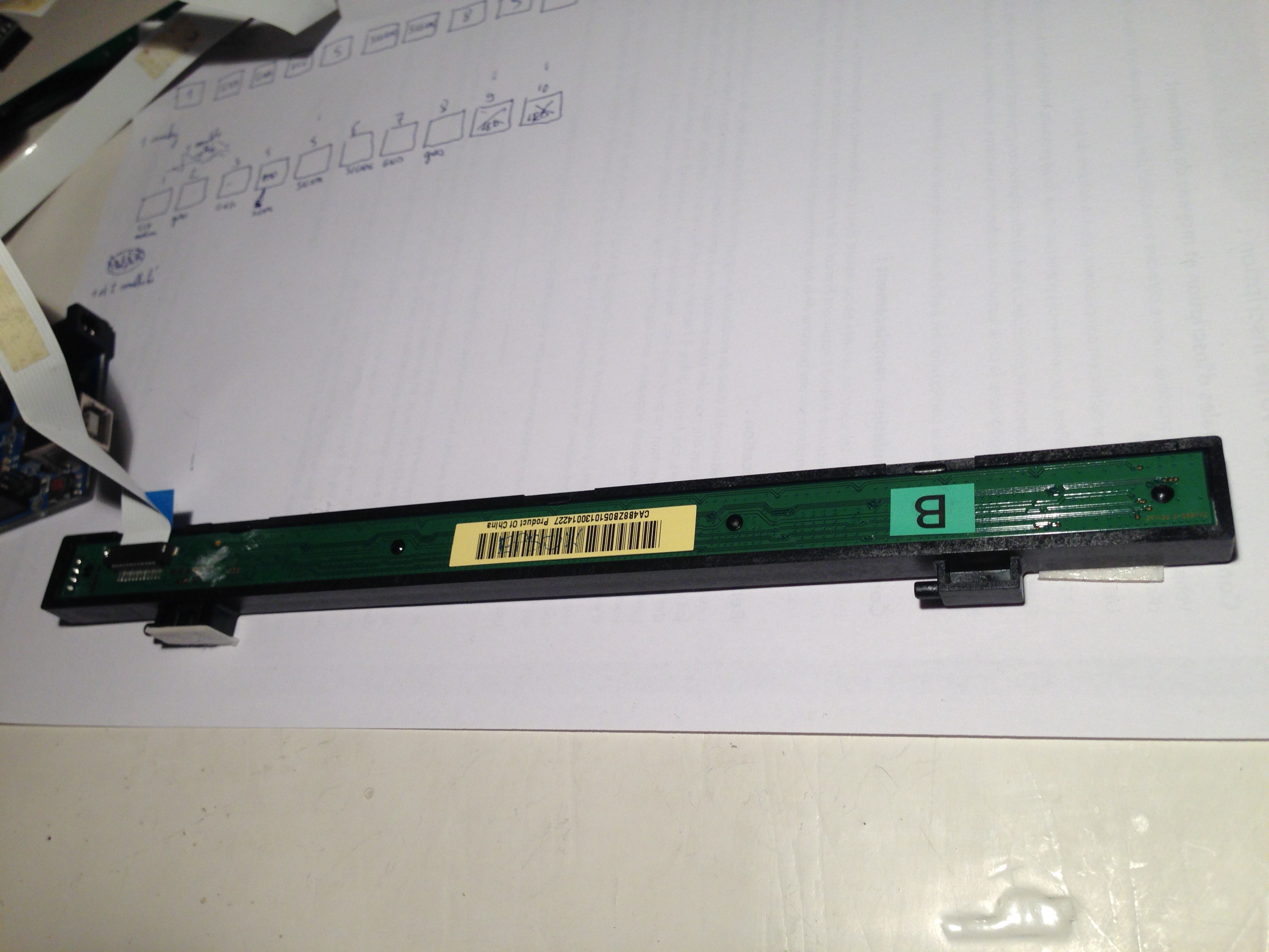
    I could access some PAD from the different line (picture 3). After a bit of testing I succeed to have a clean answer on the analog line (pictures and explanations 4 and 5).

    The CIS I was using since the beginning is from CA*** brand. Here are the lines :

    • 1 Analog
    • 2-3 GND
    • 4 VCC
    • 5 ?
    • 6 Latch
    • 7 Clock
    • 8 ?
    • 9 - 12 RGB LED

View all 16 instructions

Enjoy this project?

Share

Discussions

farzeenf609 wrote 03/15/2023 at 18:05 point

hey I am using your diy project, for a personal use, well i just couldn't understand the assembling of the frame. the use of the pexiglass, and specially the mirror. I was hoping if you could help me out a bit

  Are you sure? yes | no

RunnerPack wrote 03/14/2022 at 13:52 point

Have you thought of speeding up the framerate by dividing and conquering?  Turn on half of the lights, record the sensors, turn on the other half, record, turn on every other fourth, etc.  I'll try to illustrate:

~~~~~~~~oooooooo

oooooooo~~~~~~~~

oooo~~~~oooo~~~~

~~~~oooo~~~~oooo

oo~~oo~~oo~~oo~~

~~oo~~oo~~oo~~oo

o~o~o~o~o~o~o~o~

~o~o~o~o~o~o~o~o

I think with a simple XOR, you should be able to get the shadow data you need with only these eight permutations, instead of one per LED.

  Are you sure? yes | no

Mike wrote 05/01/2021 at 14:59 point

Very interested in DIY a touchscreen table/monitor. I came across a Youtube channel "

PeauProductions." The guy introduced 5 different ways of making a touchscreen screen. It's been 10 years based on the comments in YouTube and there was no more updates anytime soon this year, seems like they're in productions now.

Do you happen to know what that channel was about?

  Are you sure? yes | no

jimmayhew77 wrote 04/29/2020 at 12:24 point

I have two hp cis sensors. I haven't got an osiloscope. What is the best way to locate what pin goes where please. They look like 10 pin sensors.

  Are you sure? yes | no

jaymemaurice wrote 11/27/2019 at 04:57 point

If you double the CIS sensor bars and LEDs to completely surround the frame, switch between opposite pairs of LEDs and CIS bars >50hz, you can probably also use the RGB LED functionality to create "notification lights" - or possibly even do pointer color detection of somewhat reflective pointers

  Are you sure? yes | no

lam90 wrote 09/25/2018 at 14:54 point

How fast could this detect and triangulate? For example, if I were to send a bullet through the frame, would it detect? Or is it too slow for that? Just trying to think of more fun ways to draw :)

  Are you sure? yes | no

ionstorm66 wrote 04/03/2018 at 02:41 point

Have you tried make the teensy into a usb HID mouse for faster input than serial? I would love to use a dual CIS set up on my 49 inch TV as a mouse.

  Are you sure? yes | no

TheTRS80 wrote 10/09/2017 at 15:53 point

I spent much time waiting for never-delivering TouchJet Wave ... great work you did guys.

  Are you sure? yes | no

jean.perardel wrote 10/10/2017 at 08:31 point

Ididn't know Touchjet Wave, it looks great! It's a good idea for a next project! :)

  Are you sure? yes | no

jean.perardel wrote 09/21/2017 at 16:30 point

Yes, this concept of light triangulation already exist in industrial products... but when you have time, DIY is more fun! :p

  Are you sure? yes | no

adria.junyent-ferre wrote 09/13/2017 at 20:26 point

Nice project. I've been looking for reasonably priced touchscreens to make an interactive (waterproof) table and I really haven't found any good solution yet. Have you checked those touch frames they sell? The concept looks similar to yours and they promise multi-touch.

  Are you sure? yes | no

jean.perardel wrote 10/10/2017 at 08:33 point

On my last log, I ordered some CIS sensors on Ebay. If they are efficient it's gonna be possible to make large screen multitouch for less than a 100$. I keep you in touch

  Are you sure? yes | no

Similar Projects

Does this project spark your interest?

Become a member to follow this project and never miss any updates