jean.perardel
-
Magic Frame V3 is ready !
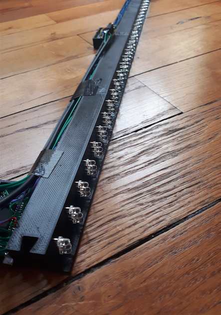
10/21/2017 at 12:32 • 0 commentsThe Magic Frame V3 is now printed and assembled.
![]()
The 3D design has now 8 LED row per piece of 13cm. Each row has 3 LED so 24 LED per piece. Which is 32 * 3 = 96 LED for a 52cm frame.
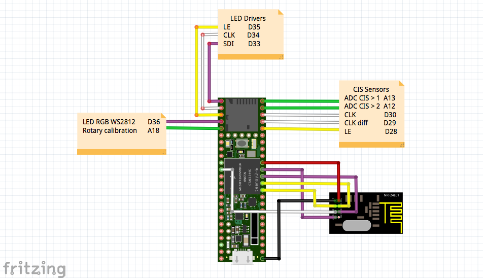
Here is the schematic :
![]()
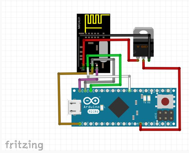
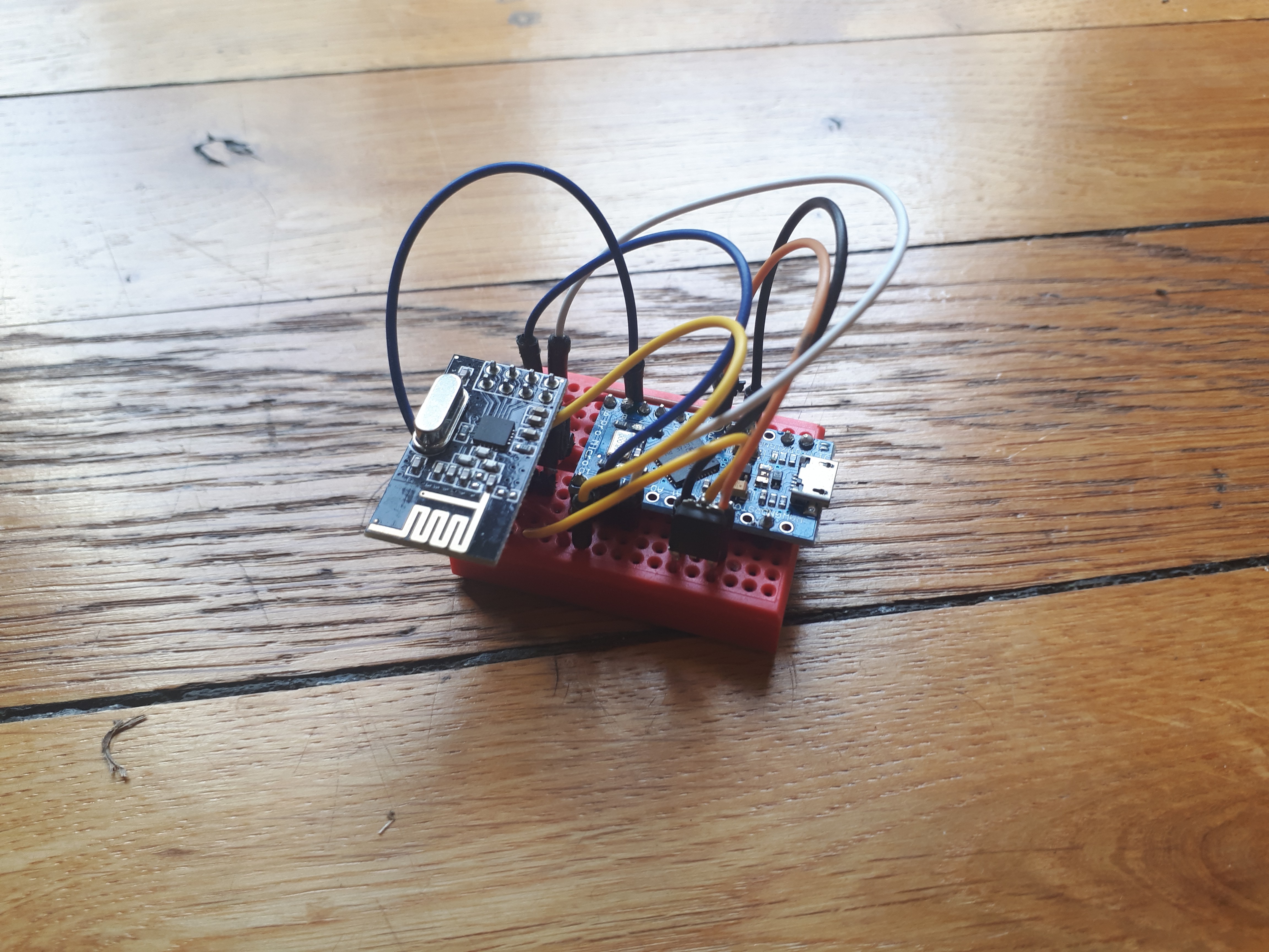
And the schematic of the Bluetooth / HID central
![]()
I didn't had much time to solder it and build a 3D printed box. This will be for later ^^
![]()
-
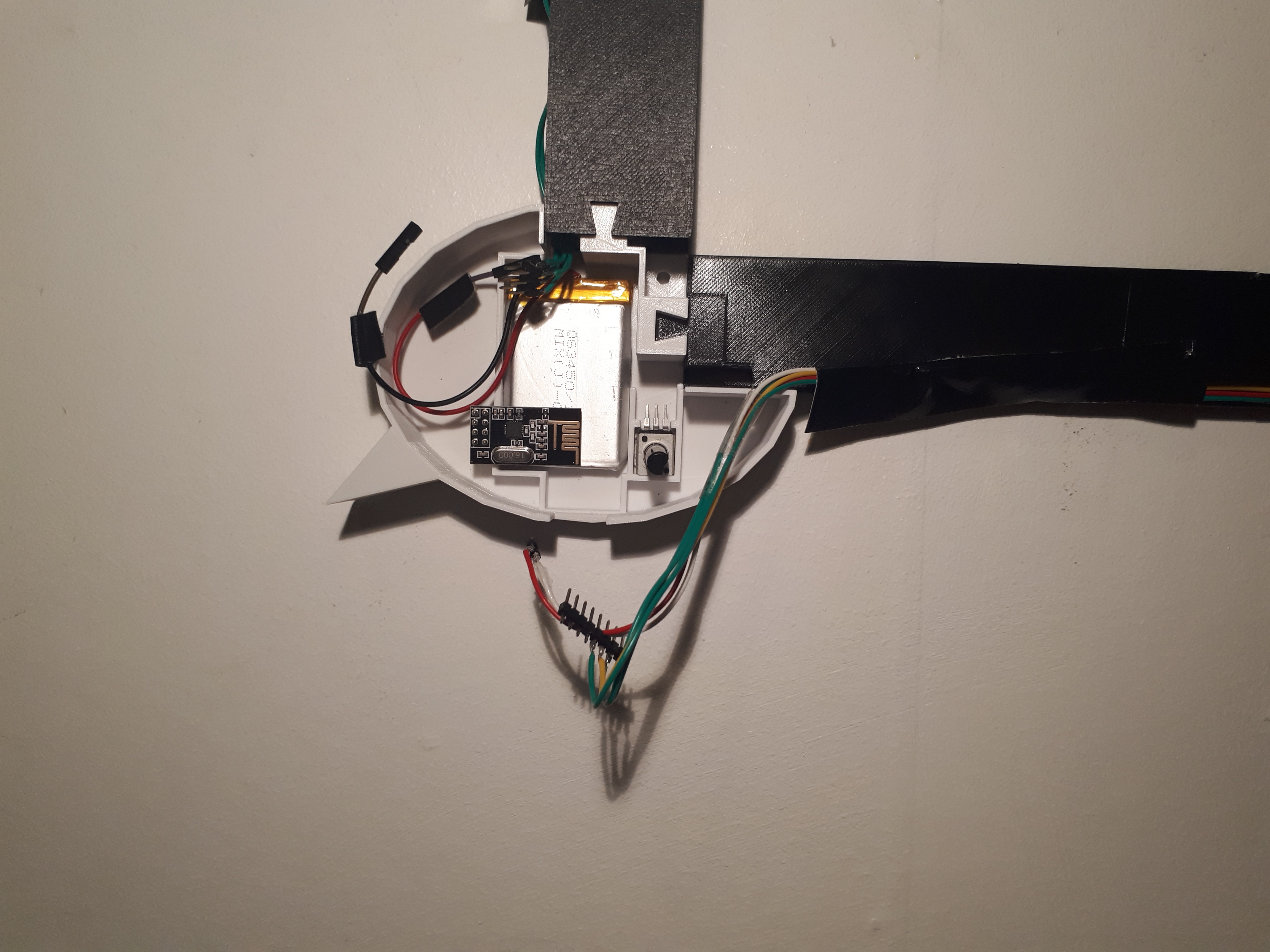
Now wireless with Bluetooth and Lipo Battery
10/16/2017 at 21:07 • 0 commentsIt's nice to have frame on your wall with a photo or painting. But to be really discret and easy to integrate, we don't want to have a black wire going away from it.
![]()
The new version of the frame now embed a 1000 mA Lipo Battery and a NRF24L01+ multi-pair bluetooth module. Now, we can get rid of the annoying micro USB cable!
![]()
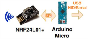
The reception is made by an Atmega32u4 board wired to a computer with a USB port.
![]() The particularity of the Atmega32u4 on the Arduino Micro board is to be able to act as an USB HID device and/or a serial port. This mean we can send some Keyboard keys, mouse position or CDC serial data.
The particularity of the Atmega32u4 on the Arduino Micro board is to be able to act as an USB HID device and/or a serial port. This mean we can send some Keyboard keys, mouse position or CDC serial data. The original program of the Magic Frame on the Teensy board also gave the possibility to act like a HID or CDC, but now we can also do it wirelessly ;-)
-
Magic Frame V2 printed and wall mounted
10/16/2017 at 18:50 • 0 commentsA lot of printing hours later....
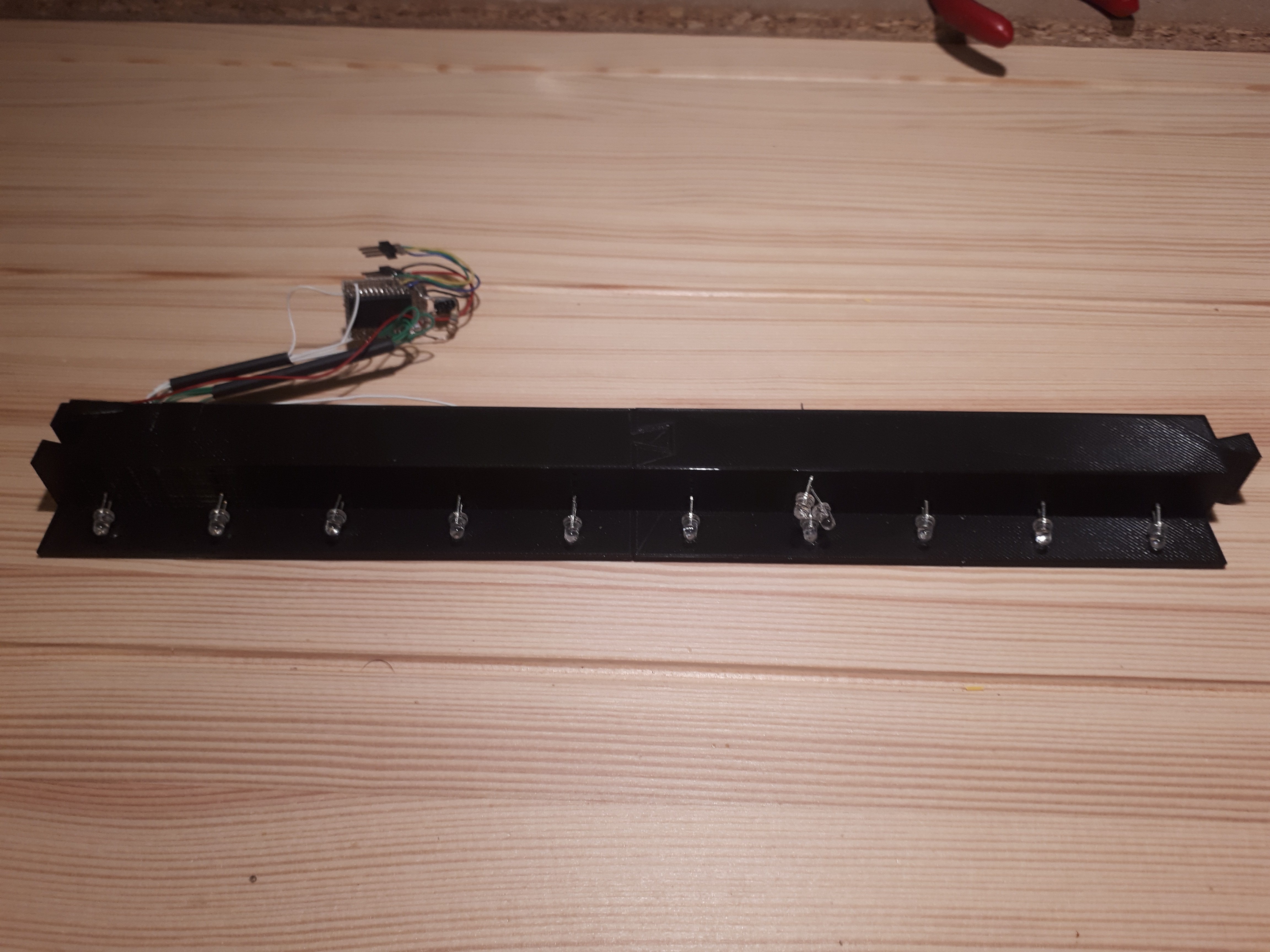
![]()
Here are 2 of my LED frame elements plugged in. I added the IR LED and the driving circuit.
I only added 1 LED per line (except on the seventh one, there are 3) because it's enough for the first frame size I want to build.
![]()
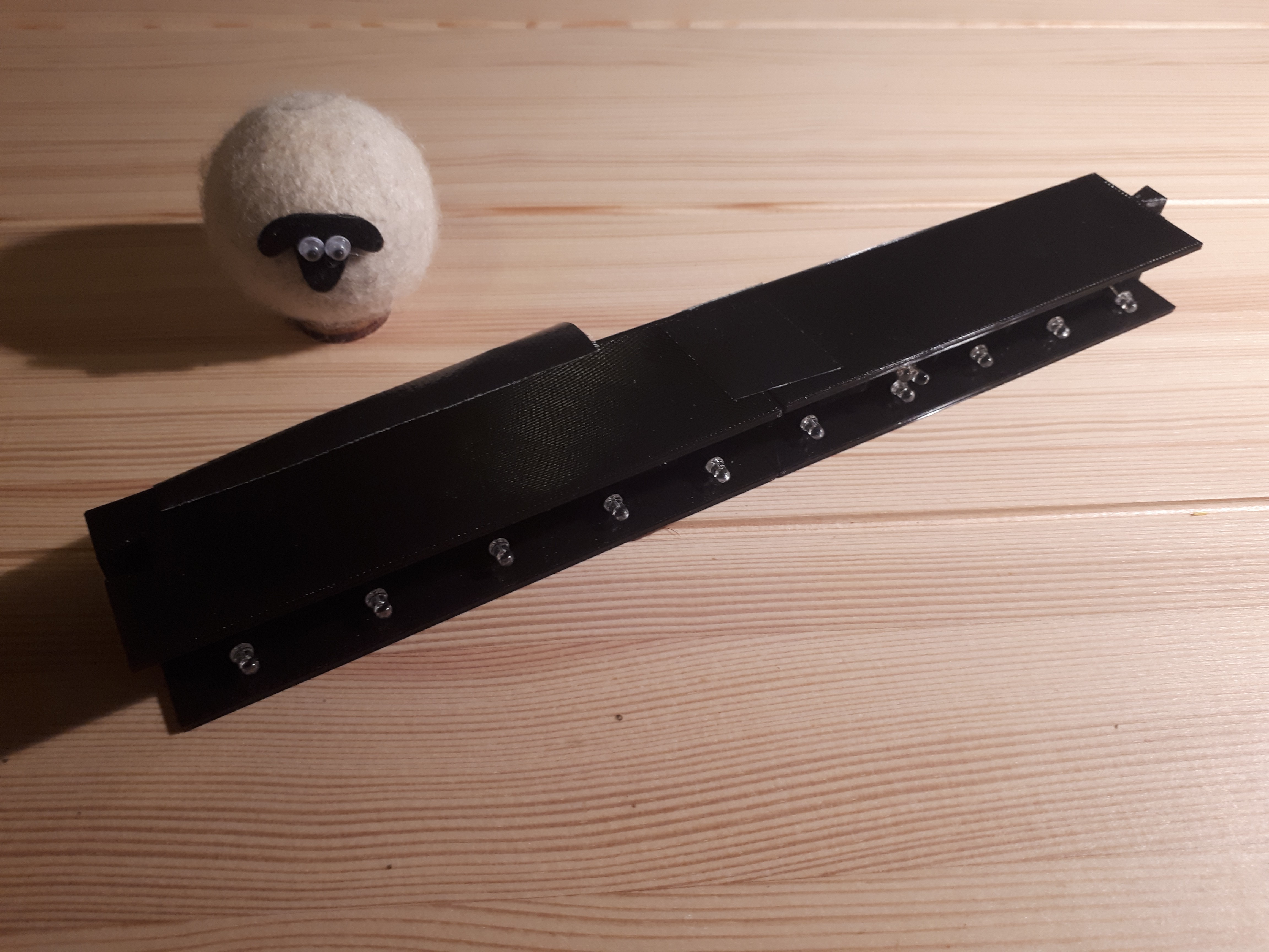
I also drew a roof for the element to hide the wires and circuit.
![]()
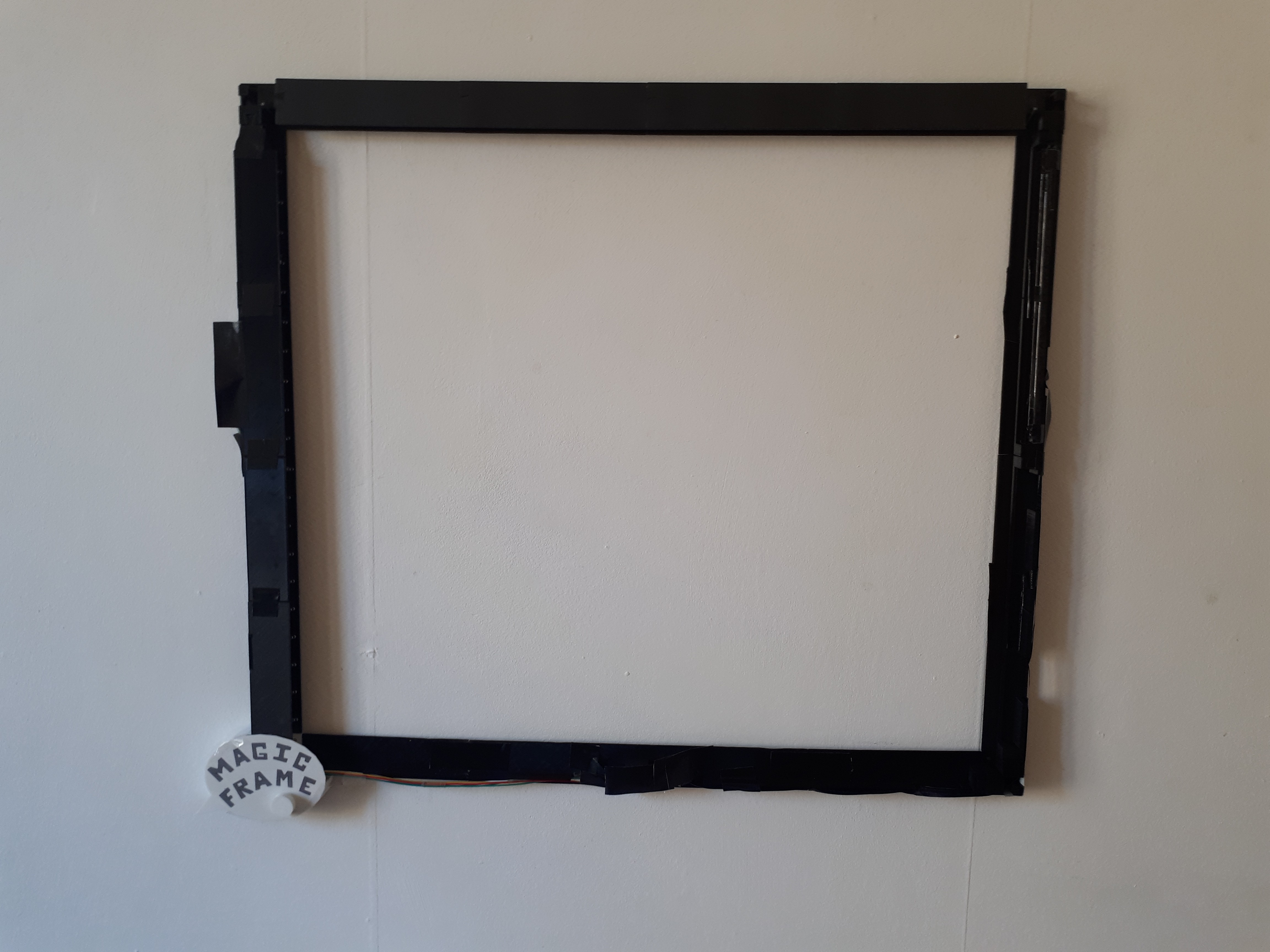
And now, the frame complete. There are actually only 4 elements at the top and bottom, but they are a bit larger.
![]()
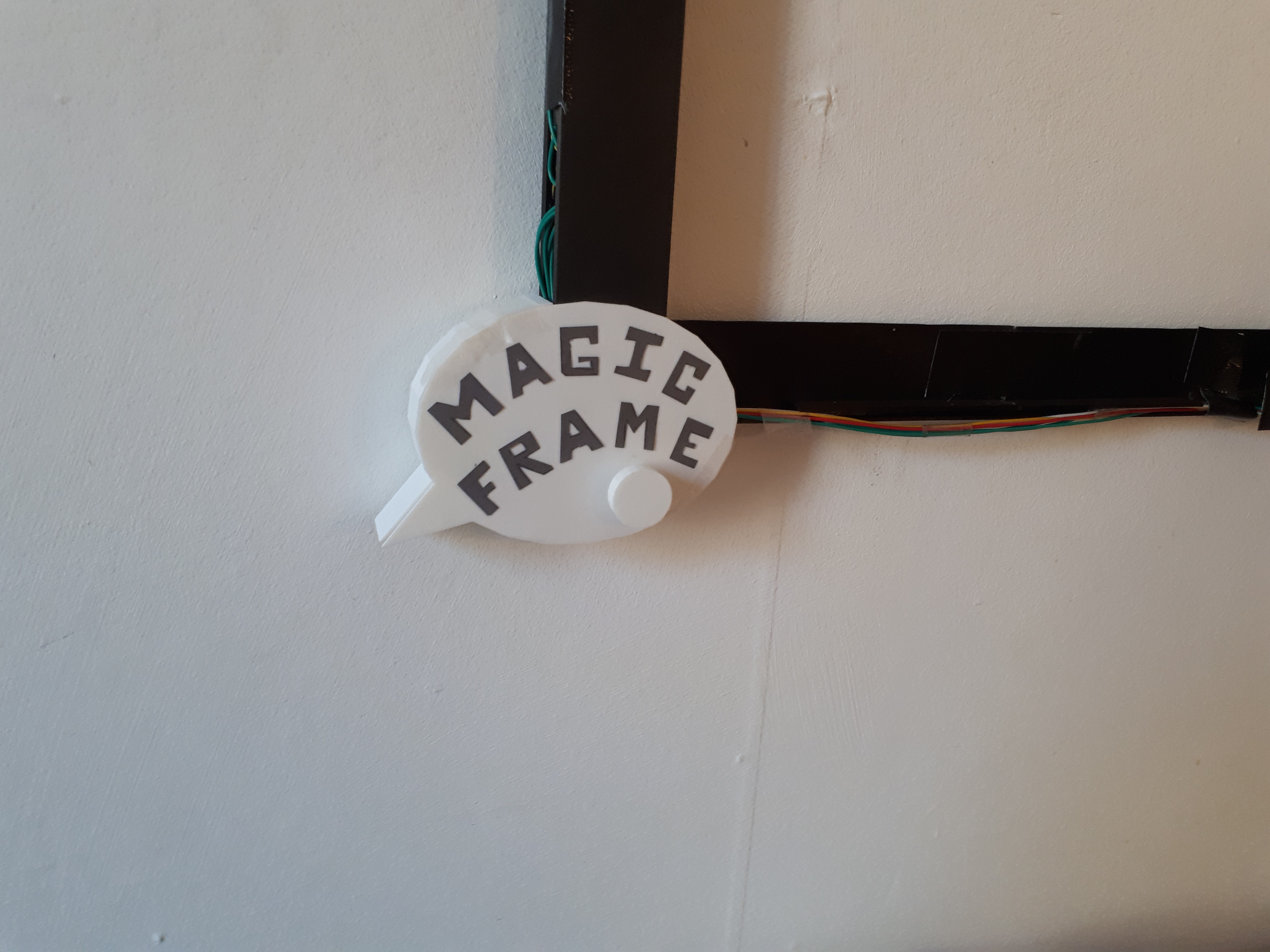
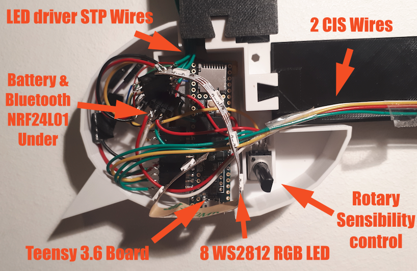
We can see the round rotary button under the word frame. You can increase or reduce the CIS's sensitivity with it.
![]()
I am really sorry... This assembly is a mess!
That's one of the reasons why I've I immediately started to drawing a Magic Frame V3 :-p
-
Magic Frame V2
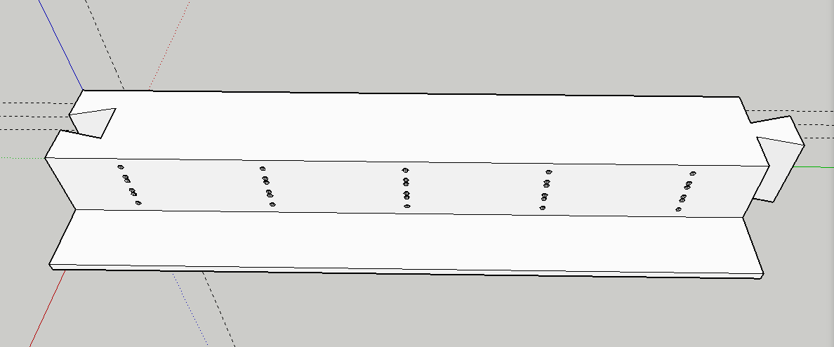
10/16/2017 at 17:59 • 0 commentsThe idea is to build an adaptable frame inspired by a jigsaw puzzle. Any size screen can be made just by adding more elements and by increasing the infrared LED power.
![]()
Here we have a "LED element" ready for 3D print. Several elements can be plugged into each other to create two emitting frames. The 5 small holes lines are for the LEDs. You can fit 3 LED per line to increase the emitting angle and the power. So this element can have 15 LED in total but it's only a 5 LED detection.
![]()
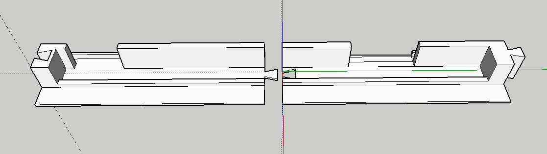
Here is a CIS element. As it's 26cm (10.2inch) large, It's printed in two parts to fit into an Ultimaker 2.
![]()
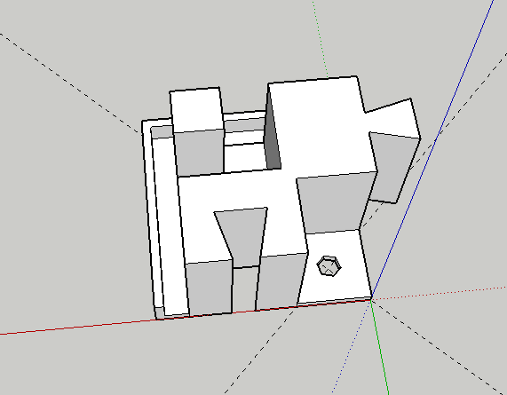
The corner of the frame to hold the structure and insert a screw for a wall mounted use.
![]()
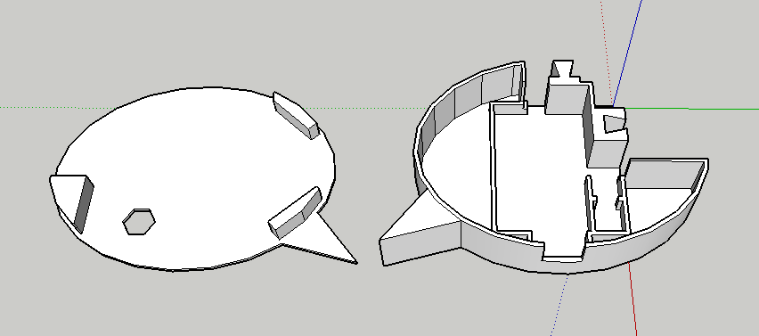
The last corner integrates the control board with most of the elements :
- A battery for wireless autonomous application
- The Teensy 3.6 control board
- A rotary going through the hole. It controls the sensitivity of the CIS sensor.
- 6 WS2812 RGB LED. As this element is printed in white. The LED gives a color to all of the enclosure. It will also help with calibrating.
![]()
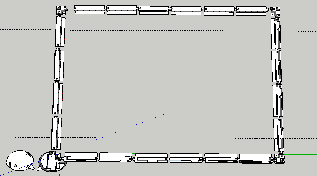
Here is the frame with all the elements. At left and at the top, we have 10 LED elements so 50 LED. At the bottom and on the right we have 6 CIS sensors.
This will make an almost perfect multitouch screen!
-
Video of my new hacked CIS sensor ^^
10/15/2017 at 23:00 • 0 commentsAs I was saying on my last log, here is the video of the CB376-67901 I hacked. It took me a while, because there isn't any information about it on the internet...
Now lets add it to the touch frame!
-
New CIS sensors bought on internet, let's HACK!
10/15/2017 at 13:01 • 13 commentsAs I was saying in a previous post, I bought some CIS sensors on Ebay.
I have already hacked several sensors I found directly in old scanners, but this method is really time consuming... and you never really know what kind of sensors you will find!
So I wanted to find a more "generic" CIS sensor, and this wasn't easy... I ended up buying on Ebay some sensors with the wrong references and no datasheet.
When I received them, it was the start of a very long day...
I started with some internet research, all the videos and blogs with people playing with CIS sensors (on their oscilloscopes most of the time). I couldn't find any information about those references.
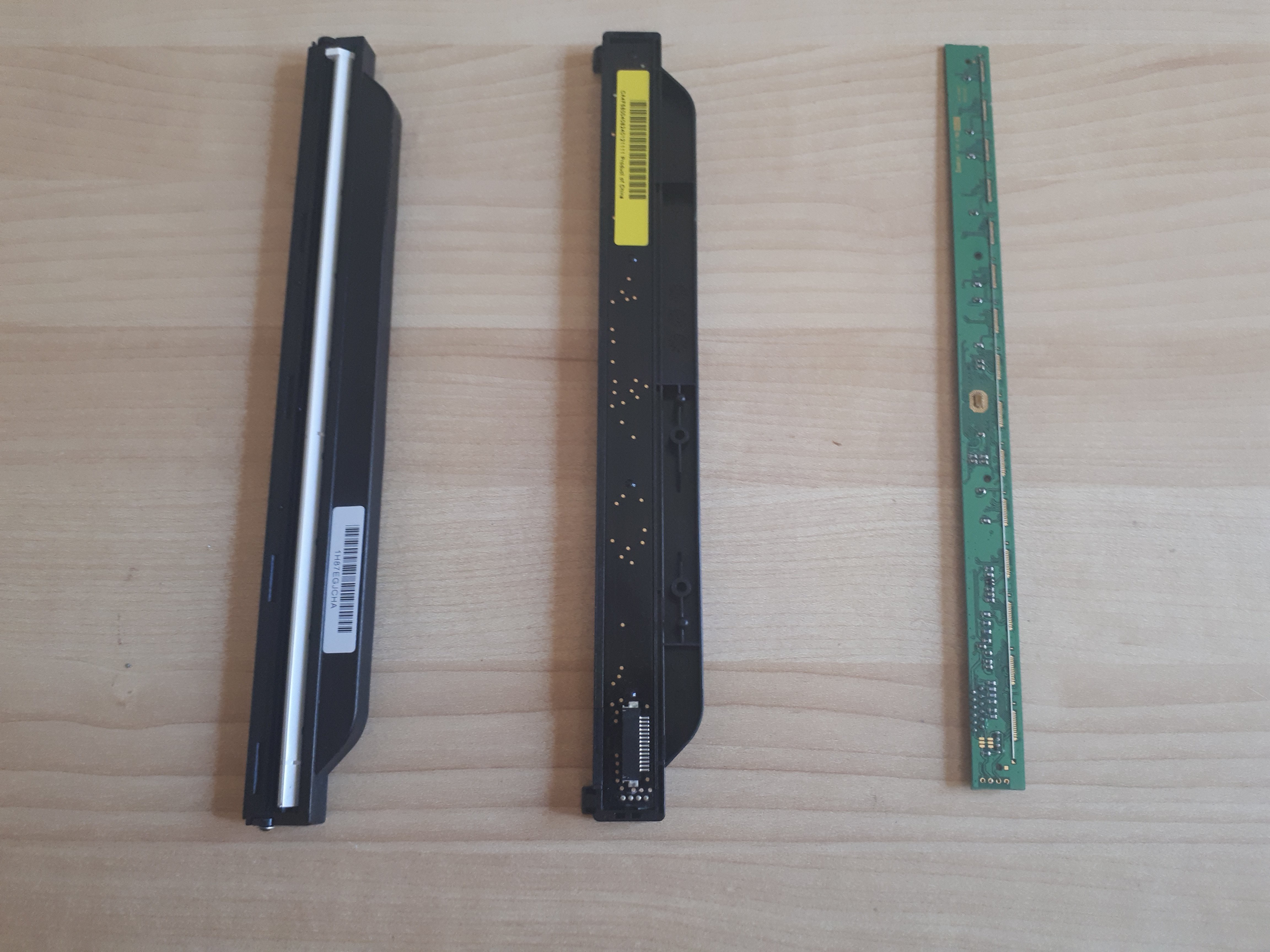
![]()
From left to right : CIS front sensor with a cover, CIS back sensor with a cover, CIS front sensor without a cover
I started with the CB376-67901. I bought two of them, so I removed the circuit of the first one to have a better visual access to the lines. This sensor has 14 lines and you need a flat flex scanner cable (you find some in every scanner) and a ZIF connector to build an interface board more easily.
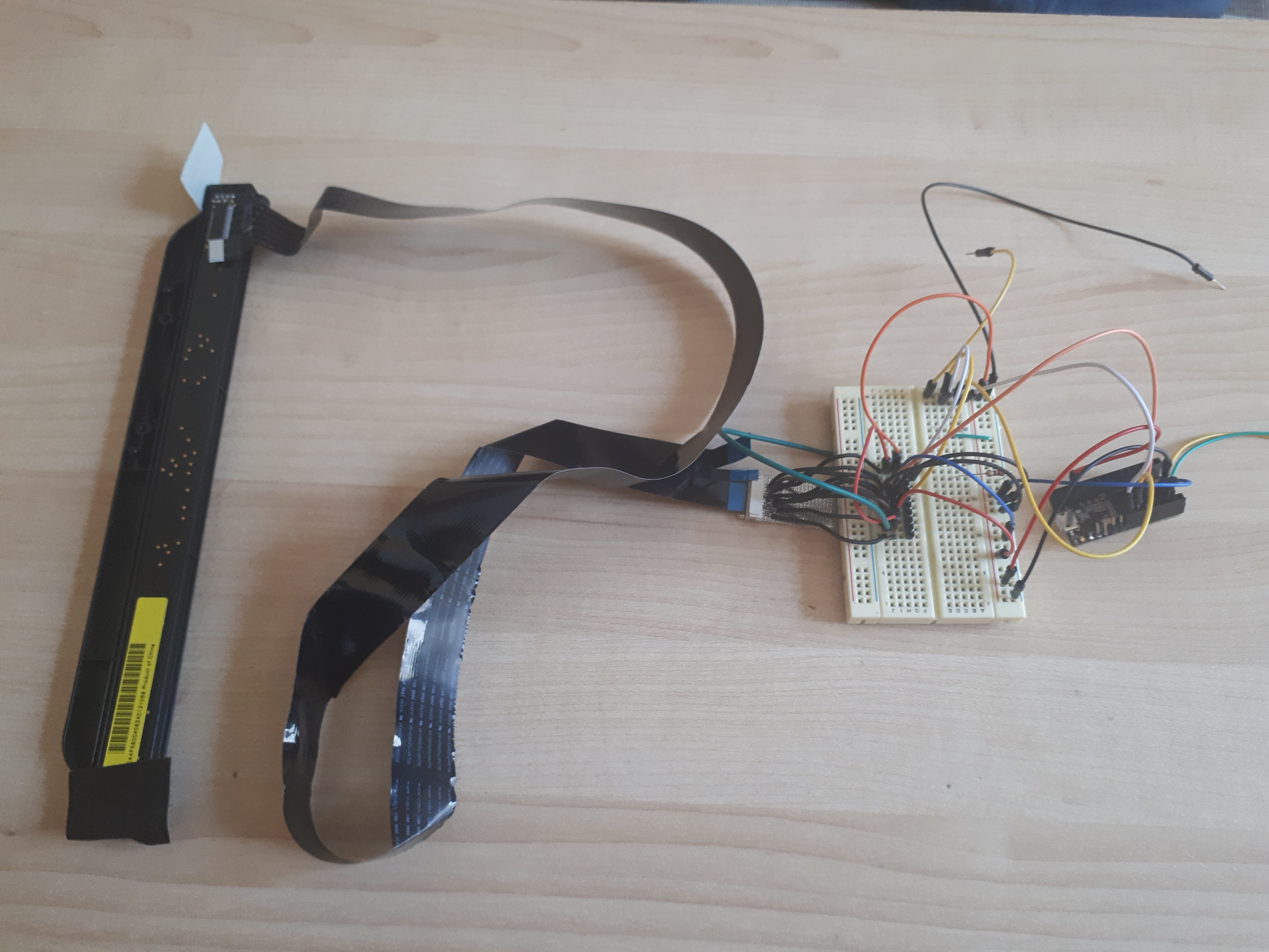
![]()
From left to right : CIS sensor, Flex cable, ZIF connector interface board, breadboard interface, Teensy 3.2.
I was able to identify :
- GND on Pin 6 and 8,
- LED pins on Pin 11 to 14
- VCC on Pin 2 and 10.
That's a good start, but still 6 Pin left for the :
- Analog output
- Clock
- Latch
- Differential lines?
- Maybe others if the protocol is different...
Then, I compared them with some CIS I used to hack and I discovered that CIS from the brand HP had the same Pin so far. Interesting! But at that time (2 years ago!) I couldn't make it work... Here is the informations I had :
- Analog output on Pin 1
- Latch on Pin 5
- Clock on Pin 9
- Still no idea for the other lines
Second step, I found an old HP scanner and opened it. And this was an amazing moment : the same plastic package, and it looked as throught it was the same Pin from the one I had so far!!
So I wired my CB376 CIS sensor directly into the flex connector of the mother board, and I could see the outputs of the CIS on line 1.
Here is the exact configuration :
- 1 Analog output
- 2 VCC (5 volts, but works with 3.3)
- 3 VCC 3.3 volts
- 4 GND
- 5 Latch
- 6 GND
- 7 differential signal (opposite to the clock)
- 8 GND
- 9 Clock
- 10 VCC
- 11 - 14 RGB LED
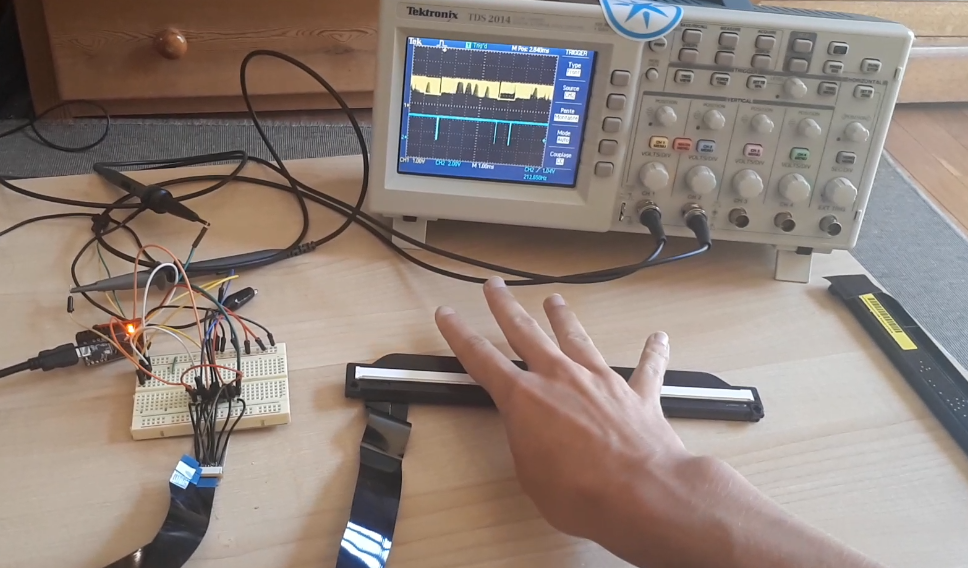
A few lines of code on the Teensy board, and now you have a new sensor to play with!!
![]()
The blue signal is the Latch (to help to synchronize), the yellow signal is the analog output. You can see 4 rounded peaks very close to each other, on the yellow signal, it's my 4 fingers. ^^ I ll upload a video soon!
I actually damaged one one of the two CB376, some pixels don't work anymore... But I still have one more sensor, and also the possibility to order more!
I haven't yet succeed at hacking the CE-841. Here is what I can say about it so far :
- 2 GND
- 5 GND
- 8 GND
- 14 LED
I need to work a bit more on this. I ll keep you posted! ;-)
-
Too many LED, lets add a driver!
10/15/2017 at 11:11 • 0 commentsI am currently working on a new frame to make the project more adaptable. As I don't want to have too many wires to solder on my Teensy board. It's probably now time to move to LED drivers.
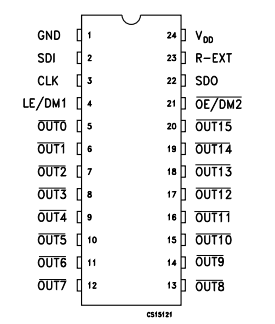
Several years ago, as I was building some LED Cubes, I used to play a lot with STP16CP05 a lot.
![]()
Those driver are very easy to use and program. Moreover, they can drive 16 outputs and you can add as many STP as you want in serial (exactly like the WS2812 RGB LED system).
To make it work,
- add VCC (3.3 or 5V) and a ground with a 10uF capa between them.
- Set the OE/DM2 to ground
- Add a resistor between R-EXT and the ground (the value depends on the output current you want, see the datasheet)
- And wire the SDI, CLK and LE signal to your control board.
- To add a second driver wire the SDO to the SDI of the second one!
You can find a test code on the GIT of the project.
-
Increase the system speed by x2.5 with a Teensy 3.6
10/15/2017 at 10:58 • 0 commentsI received a Teensy 3.6 this week to replace the 3.2 I was using. I have to say, Paul Stroffregen has done an amazing job again!
![]()
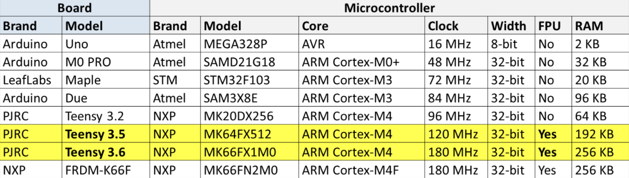
The package, is maybe a little too big, as the board has a micro SD slot embedded in it and many IO. But here are some comparison from the website OpenAudio.
![]()
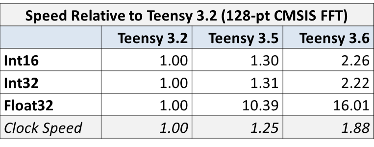
It's not on this list, but the Teensy 3.6 can be overclocked at 240MHz which makes it two and half times faster than the Teensy 3.2 I was using. I can easily double the number of LED or read twice as many pixels and still be more reactive! :-)
![]()
-
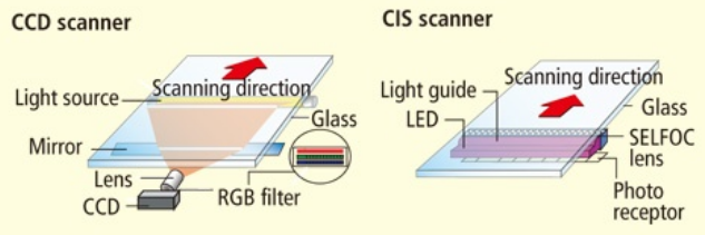
CIS or CCD ?
10/04/2017 at 14:43 • 0 commentsThere are two types of sensor in a scanner. The one I mainly used is actually a CIS (Contact Imaging Sensor) and not a CCD (Charged Coupled Device). You can either, but CCDs are really small. To cover a large screen, it's easier to use a CIS.
I've actually mistaken CCD and CIS on the video, I will change it soon...
I ordered several CIS sensors from "ON SEMICONDUCTOR" on Ebay :
-> The CE841-60111 which has 1728 sensors on 232mm
-> The CB376-67901 which has 2048 sensors on 272mm
If they work well, it's going to be a good start for building a screen frame.
This website is really insterresting in helping you understand the differences.
![]()
-
New video is online!
09/27/2017 at 21:03 • 0 commentsI've just finished my new video!! Hard work... ^^
It explains everything you need to know to understand the project. I tried to make it as funny as possible :p
Magic Frame : Turn Everything into a Touch Area
Build your own touch screen solution adapted on your TV by using some CIS or CCD sensors from old scanners
 The particularity of the Atmega32u4 on the Arduino Micro board is to be able to act as an USB HID device and/or a serial port. This mean we can send some Keyboard keys, mouse position or CDC serial data.