 Yann Guidon / YGDES
20200808 :
This design is quite good but superseded by the TAP v2 which shares the Gray counter and saves gates. See the log 120. TAP v.2 and 122. Updated Gray Counter.
The last log 111. Design of a TAP : the SIPO Controller gives an overview of the modular structure of the TAP : the shift register can "fork" into several groups, which can be selected by writing the group number in the "S" register (it's an oversimplification).
I have spent time considering various configurations for the "stump" : apart from the shared shift register (8 bits for the signature, and 8 more for the selector), the delicate part is counting the bits while presenting useful signals despite the complicated timing constraints.
The result is the following circuit : 10 DFF, 10 logic gates and 8 T-latches.
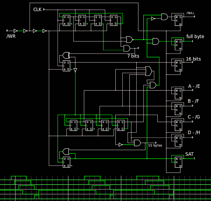
There are 4 stages with each respective functions, and 8 output signals.
- The first stage counts the bits in a byte. When 8 bits are received, the "Full byte" signal is asserted. It shares common decoding signals with the "NULL" output which is asserted when NO bit has been received yet. It's useful for the "null" instruction : just toggle /WR low and high to clear the address register.
The counter is a simple 4-taps Johnson ring counter : it's easy to implement and requires only 2 simple logic gates for the decoding. - The 2nd stage is a simple toggle counter. The output provides the LSB of the count of received bytes.
- The next counter is another 4-taps Johnson counter to count how many 16-bits words have been received. This puts the capacity to 128 bits, which is pretty good so far. Again, the Johnson counter is chosen for its simplicity and the low logic cost for decoding : the 4 outputs require only one 2-inputs gate to select a given count.
- The last stage is simply a flag that shows that the counter has overflown. It's useful because it loops back after 128 bits and this could create protocol problems and unwanted operations...
So the order of precedence of the signals is :
- NULL on means no input at all.
- Otherwise check the "full byte" flag
- If the byte count matters, always check the SAT bit.
- Then decode the counter bits.
The following table should help :
| Count (bytes) | W | ABCD | SAT |
| 0 (nothing) | 0 | 0000 | 0 |
| 1 | 1 | 0000 | 0 |
| 2 | 0 | 1000 | 0 |
| 3 | 1 | 1000 | 0 |
| 4 | 0 | 1100 | 0 |
| 5 | 1 | 1100 | 0 |
| 6 | 0 | 1110 | 0 |
| 7 | 1 | 1110 | 0 |
| 8 | 0 | 1111 | 0 |
| 9 | 1 | 1111 | 0 |
| 10 | 0 | 0111 | 0 |
| 11 | 1 | 0111 | 0 |
| 12 | 0 | 0011 | 0 |
| 13 | 1 | 0011 | 0 |
| 14 | 0 | 0001 | 0 |
| 15 | 1 | 0001 | 0 |
| 16 | 0 | 0000 | 1 |
So each module has to decode 5 bits (SAT, byte, Word, and 2 Johnson bits in Bold) to check the validity of the length, on top of the signature. It should be rather solid but still flexible and hopefully not over-engineered.
The tricky part is the timing ! This is a slow circuit so I have chosen to use some ripple-counting ideas but the devil is not on the clock signal.
All the outputs are held by transparent latches so they remain useful while the DFFs are cleared and the values are used. The /WE input is followed by buffers and explicit delays so the reset of the DFF comes after the data are latched. Otherwise it's a mess...
20200727 : a few minor tweaks and fixes have been devised, so it works better. I uncovered a useless race condition with the VHDL simulator and the "active" condition needs a couple fewer signals to test... The new version is available.
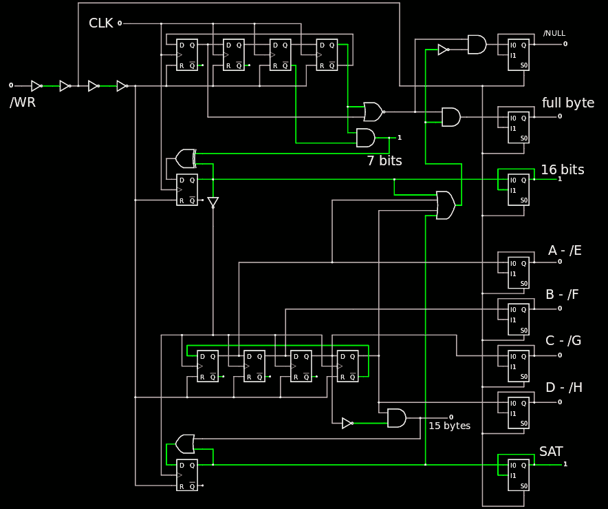
It should work better now ;-)
Discussions
Become a Hackaday.io Member
Create an account to leave a comment. Already have an account? Log In.