 Rupert Young
-
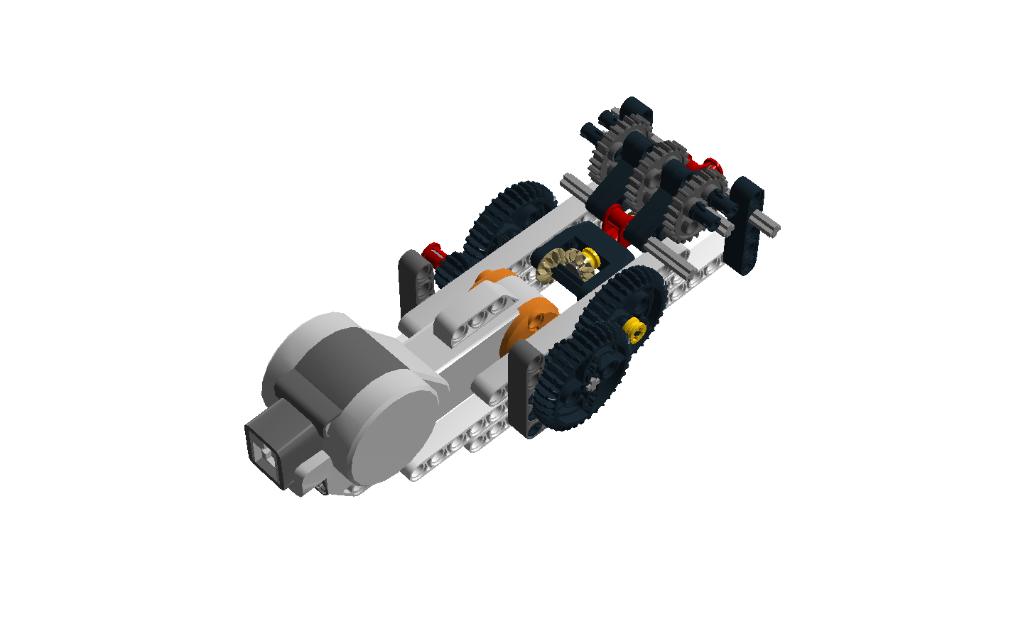
1Build perpendicular gearage
The images here show the design of the perpendicular gearage system, prepared in Lego Digital Designer.
The list of components (BOM) are in the file Perpendicular gearage.xlsx
The building instructions can be found in the Lego Digital Designer Perpendicular gearage.lxf and online here.
![]()
-
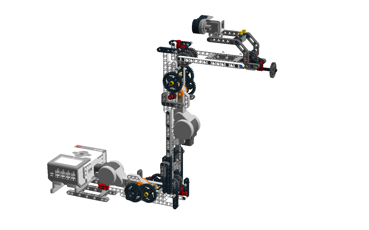
2Build humanoid leg
The image here show the design of the full leg system, prepared in Lego Digital Designer.
The list of components (BOM) are in the file Leg System.xlsx.
The building instructions can be found in the Lego Digital Designer Leg System.lxf and online here.
A Mindsensors AbsoluteIMU sensor is attached below the two yellow stoppers just behind the ultrasonic sensor with the X axis pointing in the direction of the sensor, as shown in the camera picture in a subsequent build post.
The port connections for the sensors and motors are as follows:
EV3 Ultrasonic sensor - S3
AbsoluteIMU - S4
Lower NXT Motor - B
Upper NXT Motor - C
![]()
-
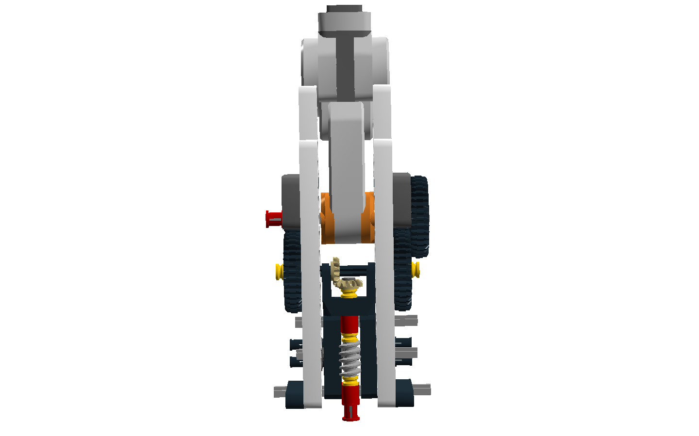
3Perpendicular gearage
For some reason these instructions won't allow two images, so here is the underside of the perpendicular gearage.
![]()
-
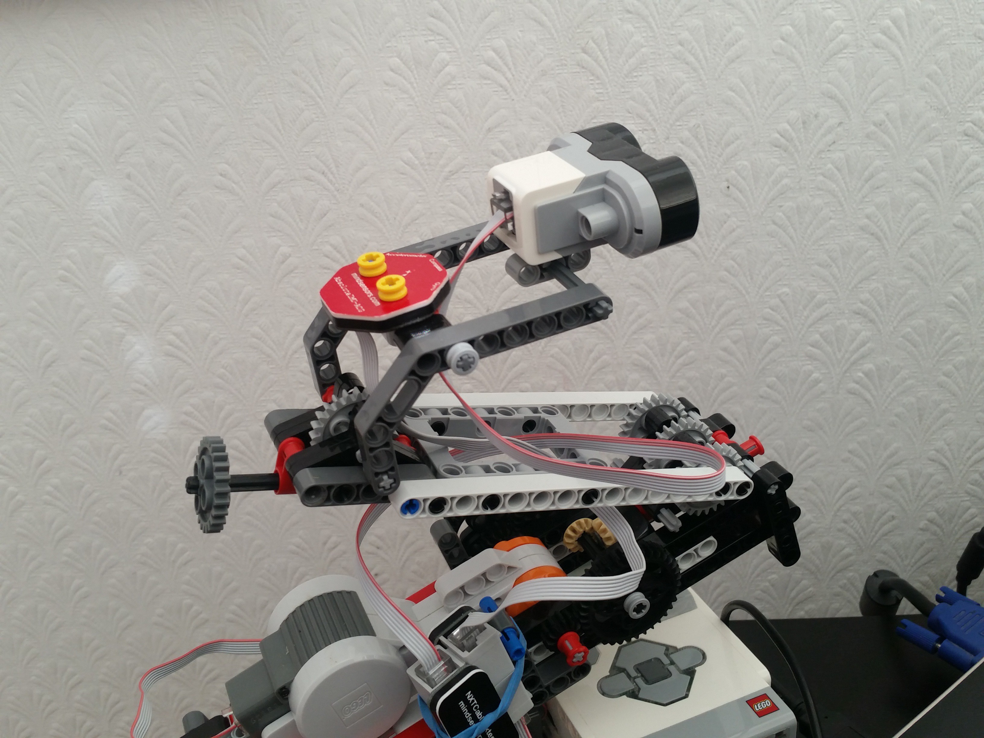
4IMU sensor
A Mindsensors AbsoluteIMU sensor is attached below the two yellow stoppers just behind the ultrasonic sensor with the X axis pointing in the direction of the sensor, as shown in the camera picture below.
![]()
RAPTA - Autonomous Humanoid Leg
Dynamic, adaptive control systems for real-world robots
Discussions
Become a Hackaday.io Member
Create an account to leave a comment. Already have an account? Log In.