-
Closeup of gear system
10/09/2017 at 13:42 • 0 commentsHere is shown closeup footage of the gear system in operation as the leg moves according to a step change function of the high-level balance reference goal.
-
Stand up, balance and proximity control - video
09/28/2017 at 12:47 • 0 commentsFor the purposes of this project the system demonstrated in this video represents the final version. As with previous versions it controls the elevation of the leg, so that it stands up, while controlling the balance sensor horizontally. It then continues to control the balance in the face of disturbances.
Additionally, it also controls proximity to an object. It does this by dynamically changing the goal of the, lower, balance control system.
-
Stand up, balance and proximity control - design
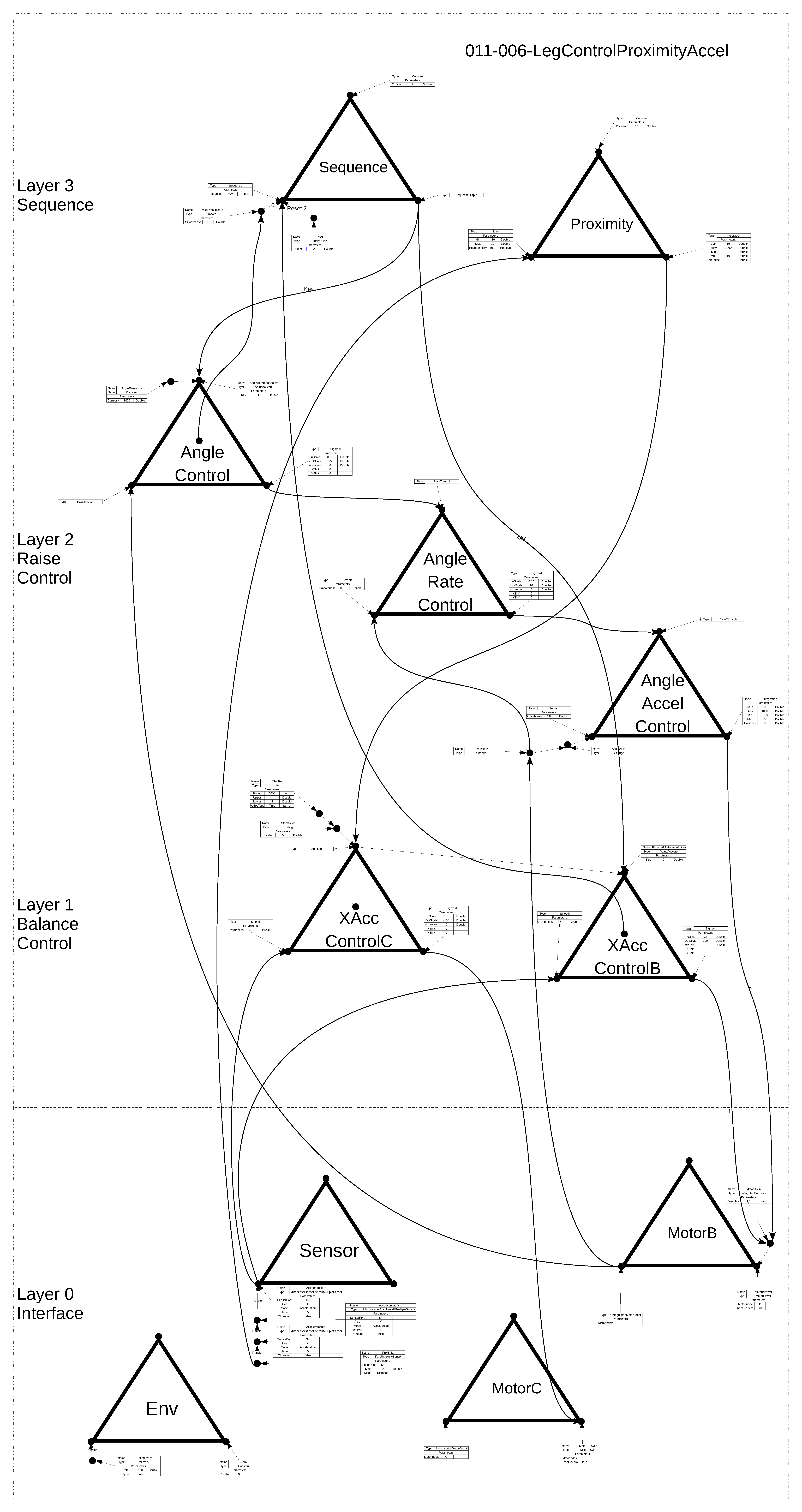
09/28/2017 at 10:59 • 0 commentsThe design shown below builds upon the previous version by adding an additional control system that controls the proximity, related to the ultrasonic sensor. The proximity control is achieved by changing the goal of the, lower, balance control system. The balance system itself controls its own perception by changing the power applied to the motors.
The resulting behaviour of the proximity control is that the top section of the leg re-balances in order to maintain the distance between the ultrasonic sensor and the object at a target value (~15cm).
This system encompasses the same functionality as all previous stages, but extends the functionality with the additional control system. This demonstrates a fundamental principle of the methodology, that the architecture is infinitely scalable; by adding the the modular perceptual control systems.
![]()
-
Stand up and balance - video
09/27/2017 at 14:08 • 0 commentsThe system demonstrated in this video initially controls the elevation of the leg, so that it stands up, while controlling the balance sensor horizontally. Then it continues to control the balance in the face of disturbances.
The video shows repeated demonstrations of this sequence with different values being set for the angle reference. The result is the whole system moves up and down, while the balance is maintained at horizontal.
-
Stand up and balance - design
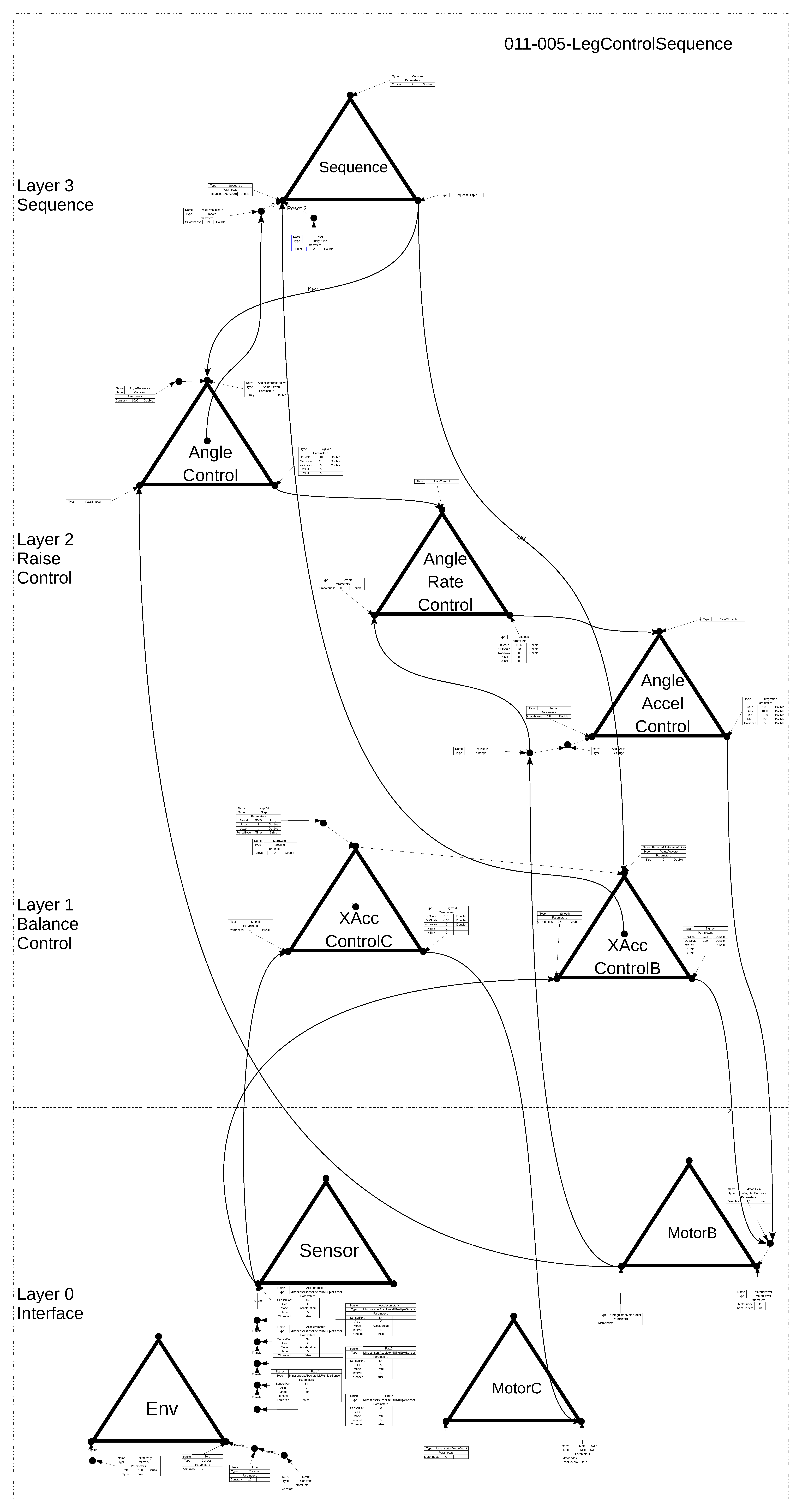
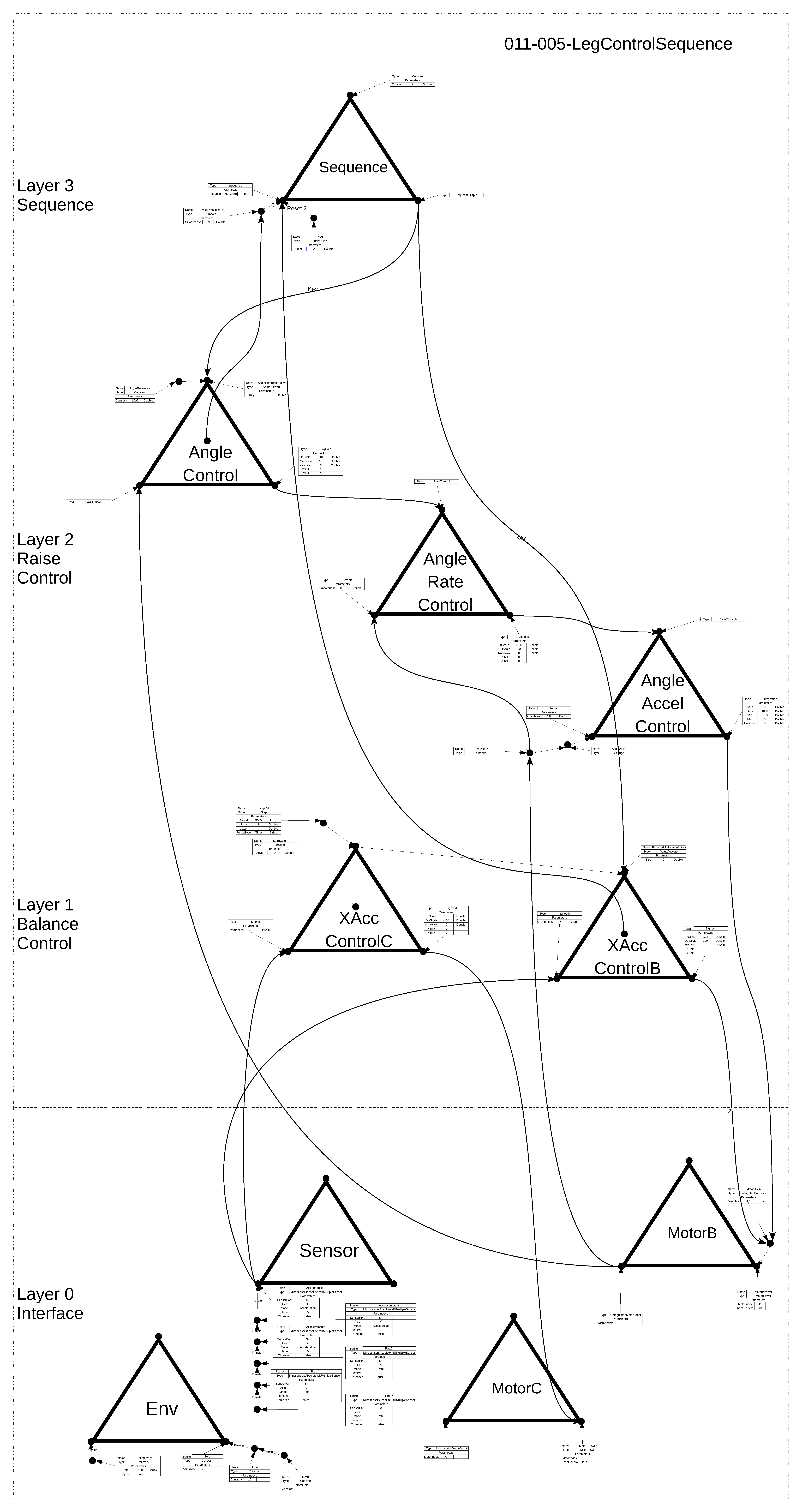
09/25/2017 at 15:43 • 0 commentsThe design below shows the hierarchy for the leg system that raises itself to an elevated level while controlling the balance. The system than continues to control balance.
This is achieved by controlling a sequence perception of two events; standing up and then continuing to balance. Firstly, the angle (tachomoter reading) of joint B is controlled by bringing it to a point where the system moves upwards from its initial position. As a smoother means to this end the joint speed and acceleration are also controlled.
Secondly, control switches to continuing balance once the angle control system reaches its goal. At this point the angle system becomes inactive.
![]()
-
Balance with two motors - video
09/25/2017 at 15:14 • 0 commentsThe system demonstrated in this video is the next step on from the previous system as two motors are used in the balancing of the system rather than just one.
Two control systems control a perception of balance by varying the power to different motors. The independent action of the two motors have complementary effects on the balance system so that the goal is reached.
-
Balance with two motors - design
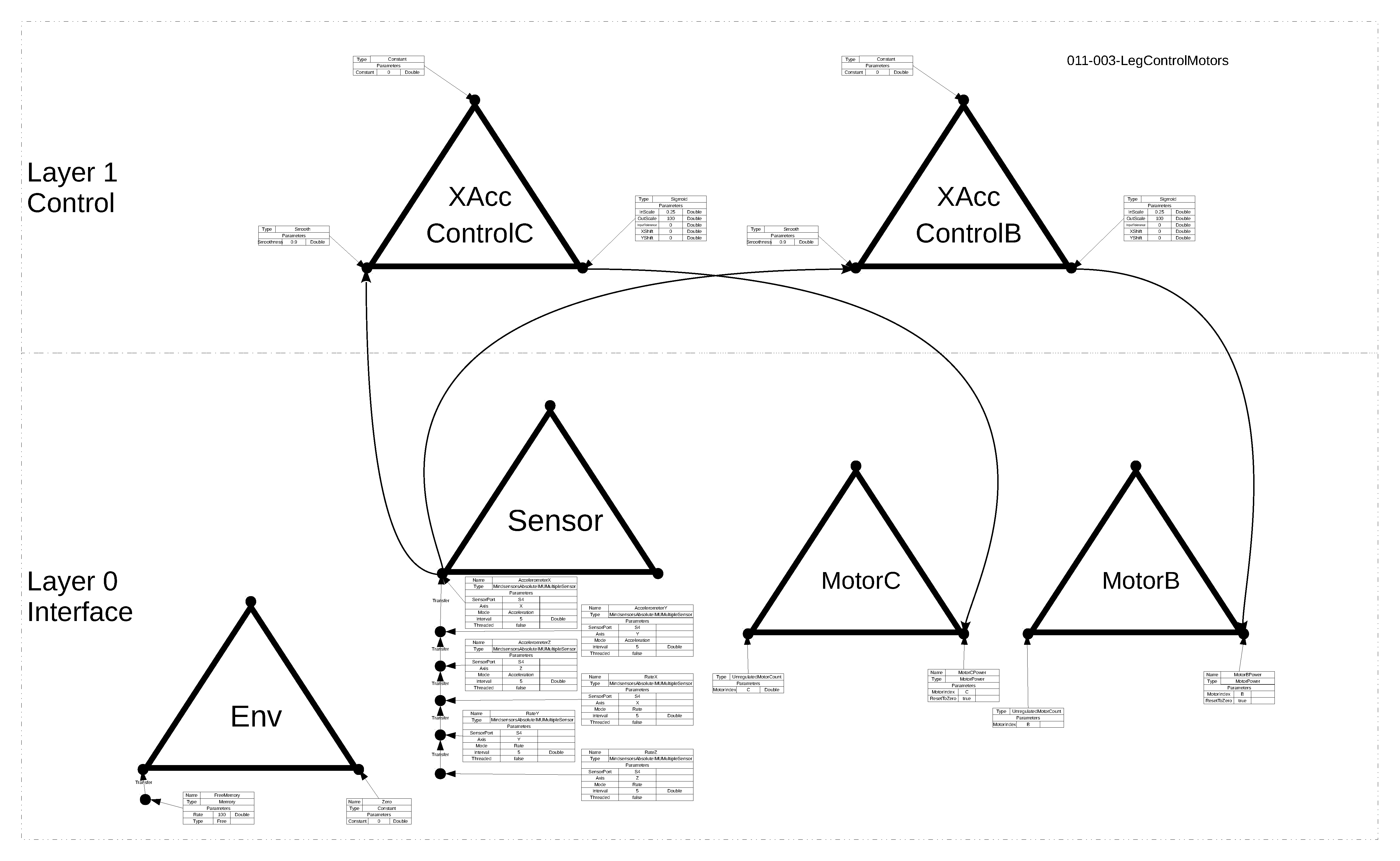
09/25/2017 at 14:49 • 0 commentsThe image below is the design layout of the leg system that balances on the basis of two motorised joints. This corresponds to the ODG file 011-003-LegControlMotors.odg added to the project files.
There are two control systems both of which control the acceleromter X value at a goal reference value. The output from each affects a different motor, to a degree that is a function of the balance error.
![]()
-
Balance with one motor - video
09/25/2017 at 13:46 • 0 commentsThe video here shows the operation of the balance system by way of a single motor. The motor power varies in order to maintain the accelerometer balance sensor value at its reference value.
-
Balance with one motor - design
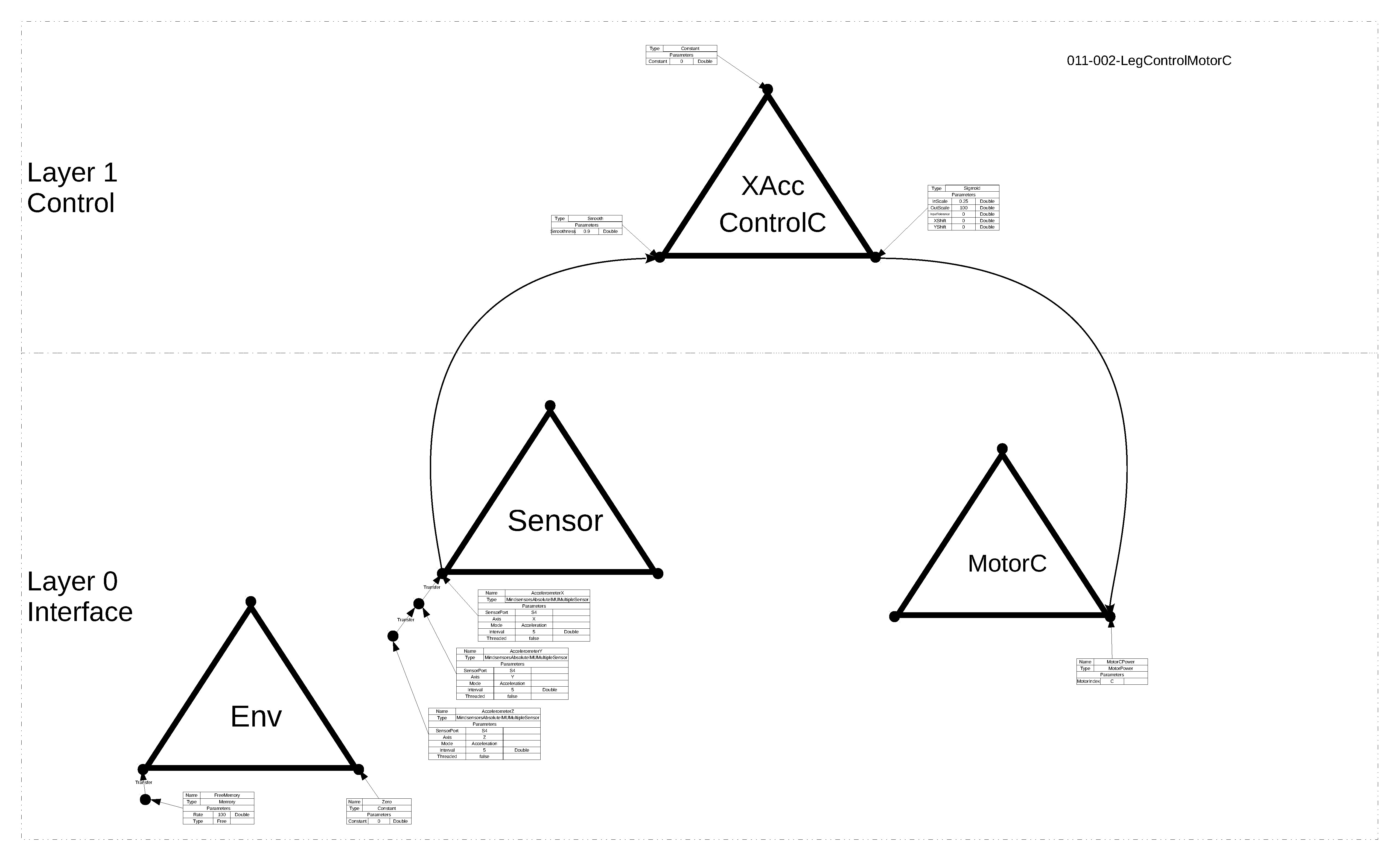
09/25/2017 at 13:28 • 0 commentsHere be the first design of the leg system on the progression towards the full system. This corresponds to the ODG file 011-002-LegControlMotorC.odg added to the project files.
There is a single control system which controls the acceleromter X value at a reference value by setting a motor power proportional (sigmoid) to the balance error. The X value of the accelerometer is zero when it is level.
![]()
-
Software platform example
09/25/2017 at 11:35 • 0 commentsThe video below shows basic usage of the PCT Monitor graphical user interface for visualisation of the data involved with a live environment. The particular control system design is shown in this image. The configuration controls a perceptual sequence, of the system standing up while controlling balance and then maintaining balance in the face of disturbances.
![]()
The video demonstrates and describes some of the features of the monitor.- the GUI connects over the network to a running live robot system,
- each of the control systems in the configuration can be viewed as a set of live signal values,
- graphs can be created to plot any of the signals,
- parameters on the live system can be modified via the GUI during execution.
RAPTA - Autonomous Humanoid Leg
Dynamic, adaptive control systems for real-world robots
 Rupert Young