Sky Carter
-
About That Video...
08/21/2014 at 00:45 • 0 comments20140820 Wednesday
About that Video...
I'm really camera-shy. T__T Plus, I have no video-editing software on the school's computer to record myself. But this probably does not matter, since my home won't have an established internet connection until tomorrow anyway. (Yeesh.)
But if you'd like to know more about me, or have any questions, please check here, or visit my facebook page!
https://www.facebook.com/skyrakruz
Because my family and friends enjoy their privacy, I cannot fully open my profile to the public. Please send me a friend request first, state who you are, and message me at will. I'll try to reply on time, between classes. :)
Peace,
--Sky C.
-
Additional Images
08/21/2014 at 00:22 • 0 comments![]()
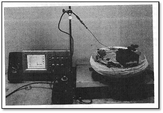
Figure 2 (Skyhunt): The Completed Ring-Laser Gyro. ^
![]()
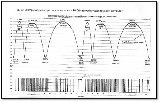
Figure 3 (Skyhunt): The Oscilloscope Results. ^
![]()
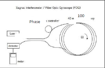
Block Diagram (Skyhunt)
![]()
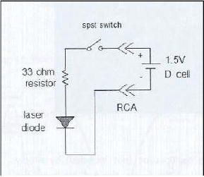
Laser Circuit (Skyhunt)
This circuit uses a current limiting resistor to lower the voltage more
suitable for the diode. The diode outputs ≈ 1mW @ 1300nm.![]()
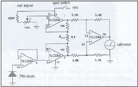
PIN Diode Circuit (Skyhunt)
This circuit uses a gain of 11 and a manual null adjust to zero out the output. This circuit is known as a "common mode rejection amplifier", which is used to reduce noise on the output. The Ouput could be displayed by either a Multimeter or an Oscilloscope.
-
Troubleshooting
08/21/2014 at 00:08 • 0 commentsTesting & Troubleshooting
-
Upon completing the assembly of the ring-laser gyroscope, the gyro’s voltmeter would not properly read the changes in voltage. Each step of assembly was revisited to isolate the problem. Phase-controller and Photodiode found to be improperly set, and adjusted accordingly to the requirements provided by the manual. Problem isolated to the voltmeter, which was revealed to have low batteries. The voltmeter was exchanged for another, and the problem resolved.Figure 2 (Skyhunt)
The gyro was then connected to an oscilloscope to display the bright and dark bands of incoming interference patterns in the light. Output waveforms were “snakes”. Determined that higher frequencies = brighter light bands, and lower frequencies = darker bands. Gyro was extremely sensitive to the slightest change / interference, and reacted seismically to the lightest vibration around it, making an accurate reading for rotation without some system or program of filtering noise next to impossible. This resulted in the gyroscope being unable to properly calibrate.Figure 3 (Skyhunt)
Switched to DC couple on the oscope and adjusted the Phase-controller up and down, to bring in a brighter or darker interference pattern to the signal. Raised the amplitude of the signal with PIN diode, and adjusted the phase-controller until the lowest (darkest) signal possible was achieved. Counted bright and dark bands: the more bands per second indicated an increase or decrease in speed of rotation. Dark-to-light and light-to-dark was indicative of the direction.
1-D Laser-Ring Gyroscope
A 1-dimensional, laser gyroscope...on a pizza pan.