Bruno Laurencich
-
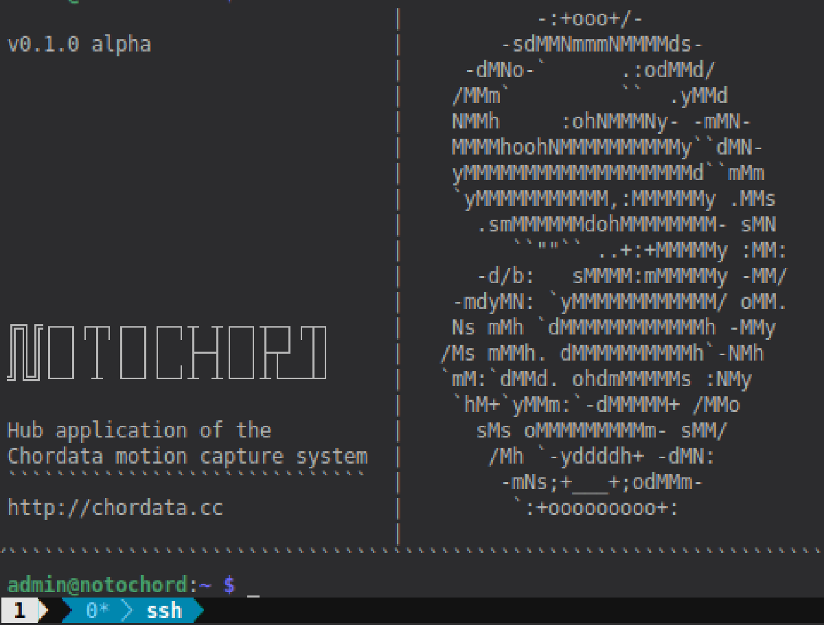
Release Note [v0.1.0 ALPHA]
08/22/2018 at 19:30 • 0 comments![]()
Dear Chordata followers and collaborators, we have some awesome news to share with all of you: the day has come when we finally release the core of Chordata’s motion capture system. In this initial release, we’ll make our code repositories public so that anyone with a little bit of electronic and/or coding experience can go ahead an dive into the intricacies of our project. Those brave enough will also be able to download set up their own motion capture system by downloading the sources, and building the system from scratch. There’s at the moment no official documentation, but we’ll be happy to assist those adventure seekers that wish to take their chance at building Chordata with the materials at hand.
Be aware that this is an alpha release: we’ll keep on testing and improving the system in the next months (and we’ll obviously let you know about all of the improvements to come). One of the things that drives us when displaying the code is finally being able to expand our scope of collaborators, so feel free to write us through Hackaday discussion or with the form that you can find in our website.
That’s all fine and dandy, but there will be more to come. We’re preparing Chordata’s documentation so that anyone can access the core functionalities without the need of any sort of expertise. We’re also preparing a Tindie store in which you’ll be able to purchase our pre-built kits: this will enable people without knowledge of electronics to build and use Chordata so that they can apply its functionalities in their personal projects.
What this means is that we’re just beginning, as Chordata’s purpose is reaching both those who already work with electronics and the general public so that the worlds of visual art, game design, animation, movement computing, gait analysis, physical therapies, among others, can also benefit from the possibility of capturing motion in a more accessible and open system. We have no official release date, but we expect all of these additional releases to be done during the next semester.
Link to the sources repositories: https://gitlab.com/chordata
Or download the working files at: https://hackaday.io/project/27519-motion-capture-system-that-you-can-build-yourself#menu-files
Don’t hesitate to write us with all of your doubts (or simply to express your appreciation, as that’s what drives us further). We’re eager to see your reaction!
-
New video, web and social
08/14/2018 at 18:27 • 0 commentsToday we've launched a new video explaining all the features of Chordata, the Open Source motion capture system that you can build yourself. Make sure to check it out in our YouTube page and give it a like.
We’ve also launched our new website, which features links to all of our social networks. With all of these tools, you’ll now be able to follow the evolution of Chordata without missing a single step of the process.
We hope you enjoy them!
All this couldn’t been possible without the work of our new team members, Juancho and Flavia, who are helping out with communications and social media.
If you want to give a little help to the project, is as easy as giving it a like here on hackaday, which will help us to stand out on the Human-Computer Interface round, in the current edition of the Hackaday price.
-
Hackaton postmortem
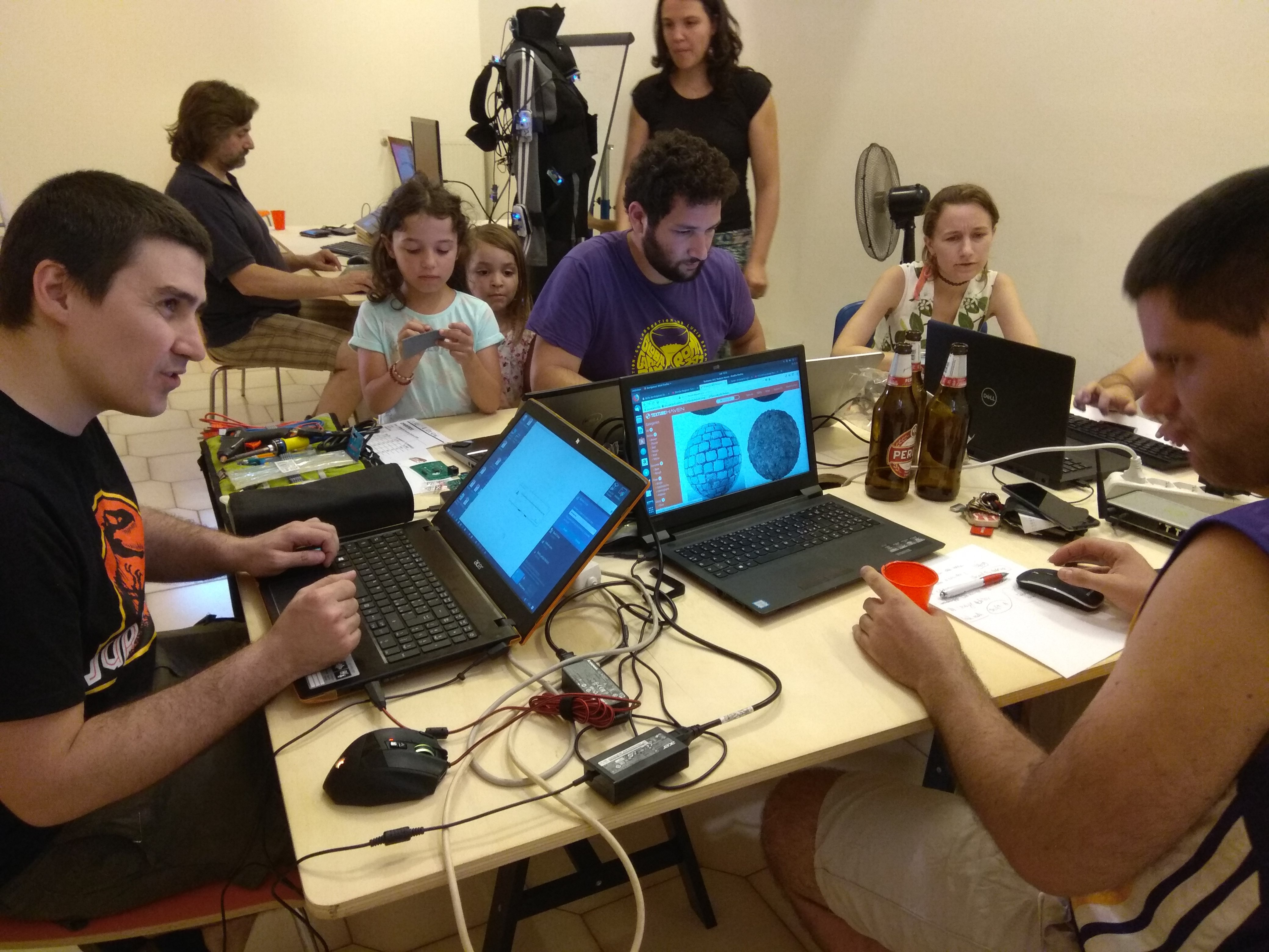
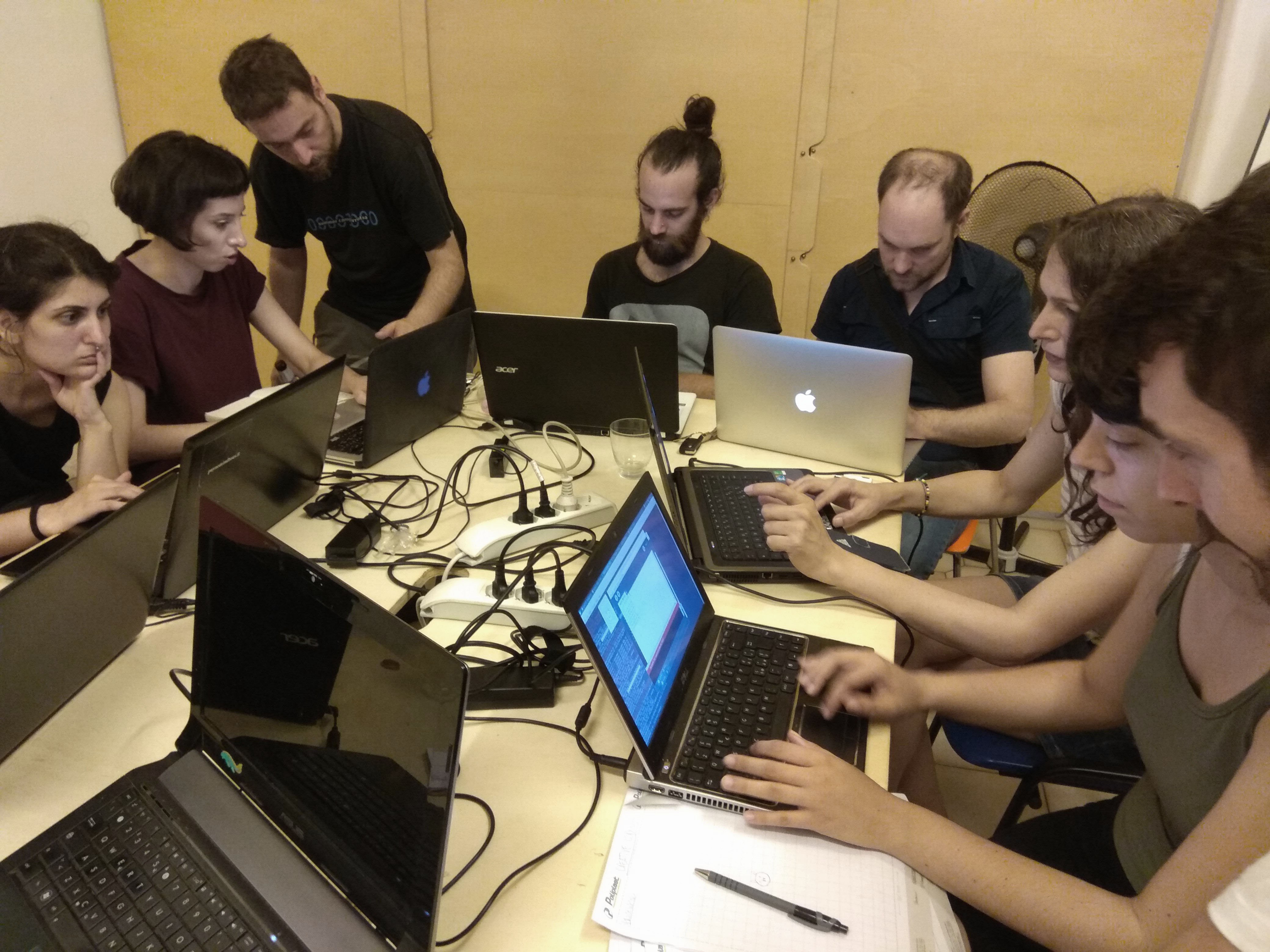
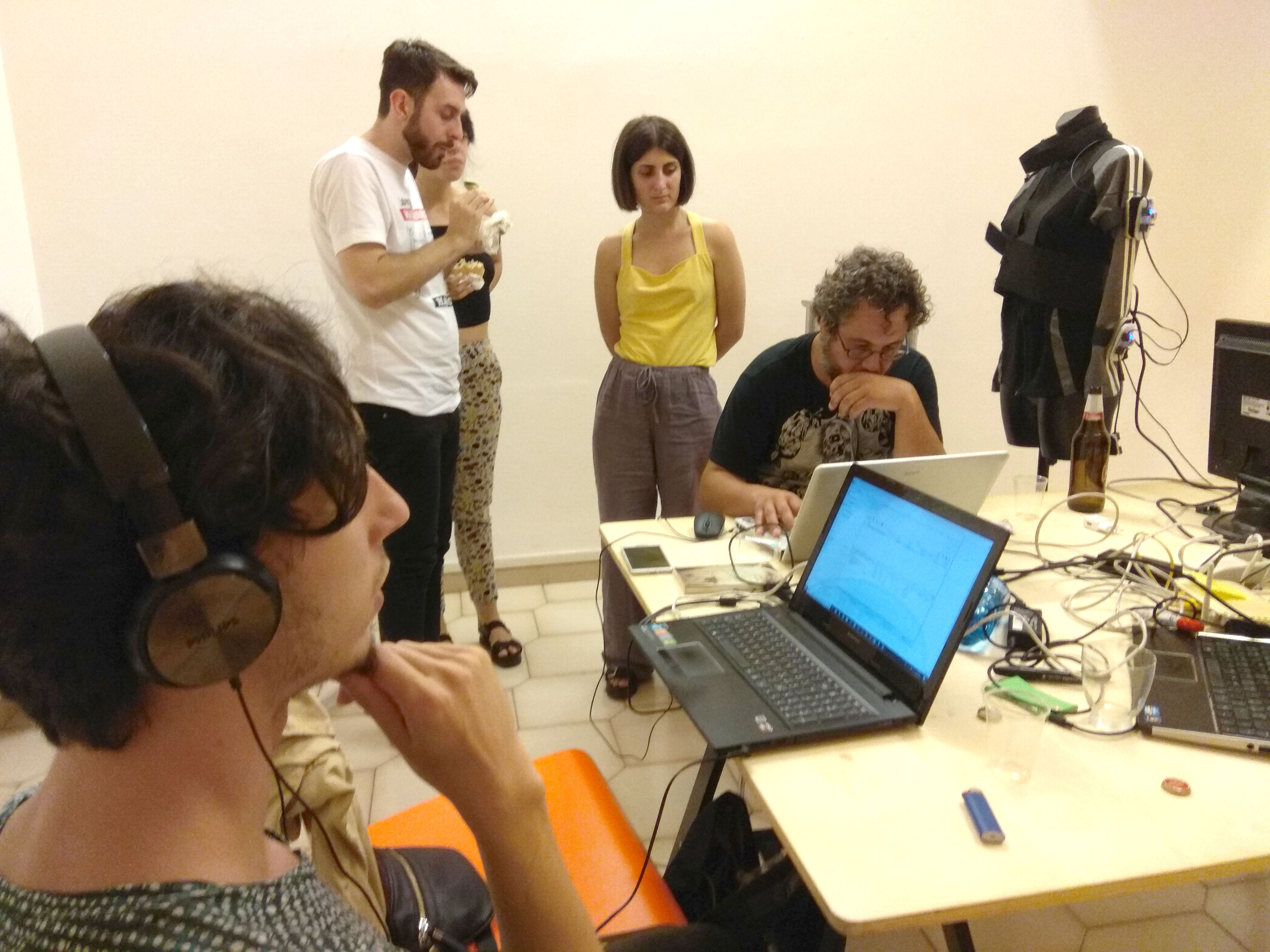
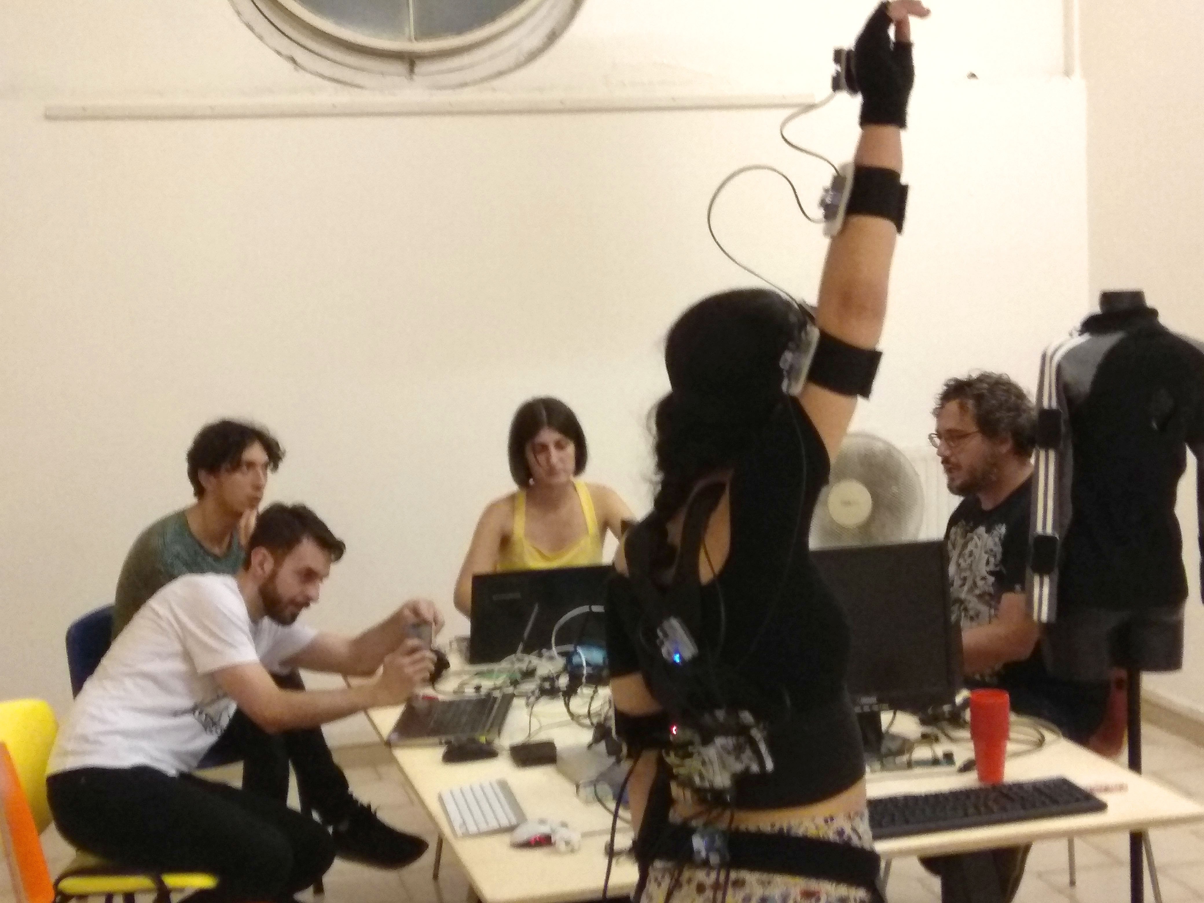
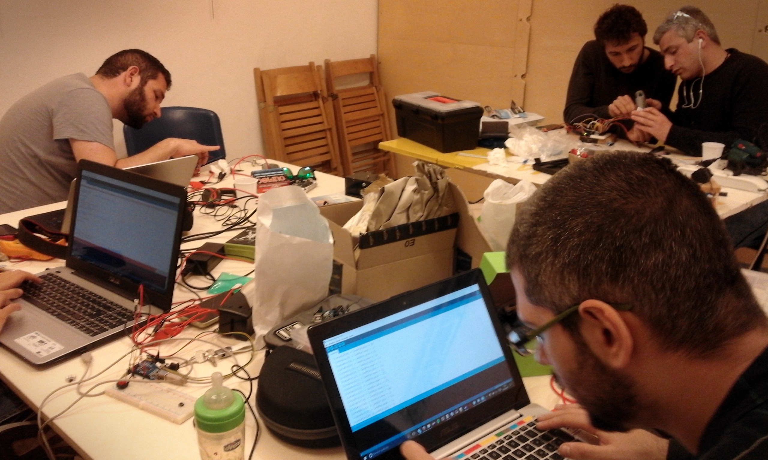
07/29/2018 at 14:45 • 0 commentsThe motion capture hackathon took place last week . It was great to see the Chordata system used on so many different projects!
Here's a quick recap of the work done:
![]()
![]()
![]()
![]()
![]()
![]()
![]()
![]()
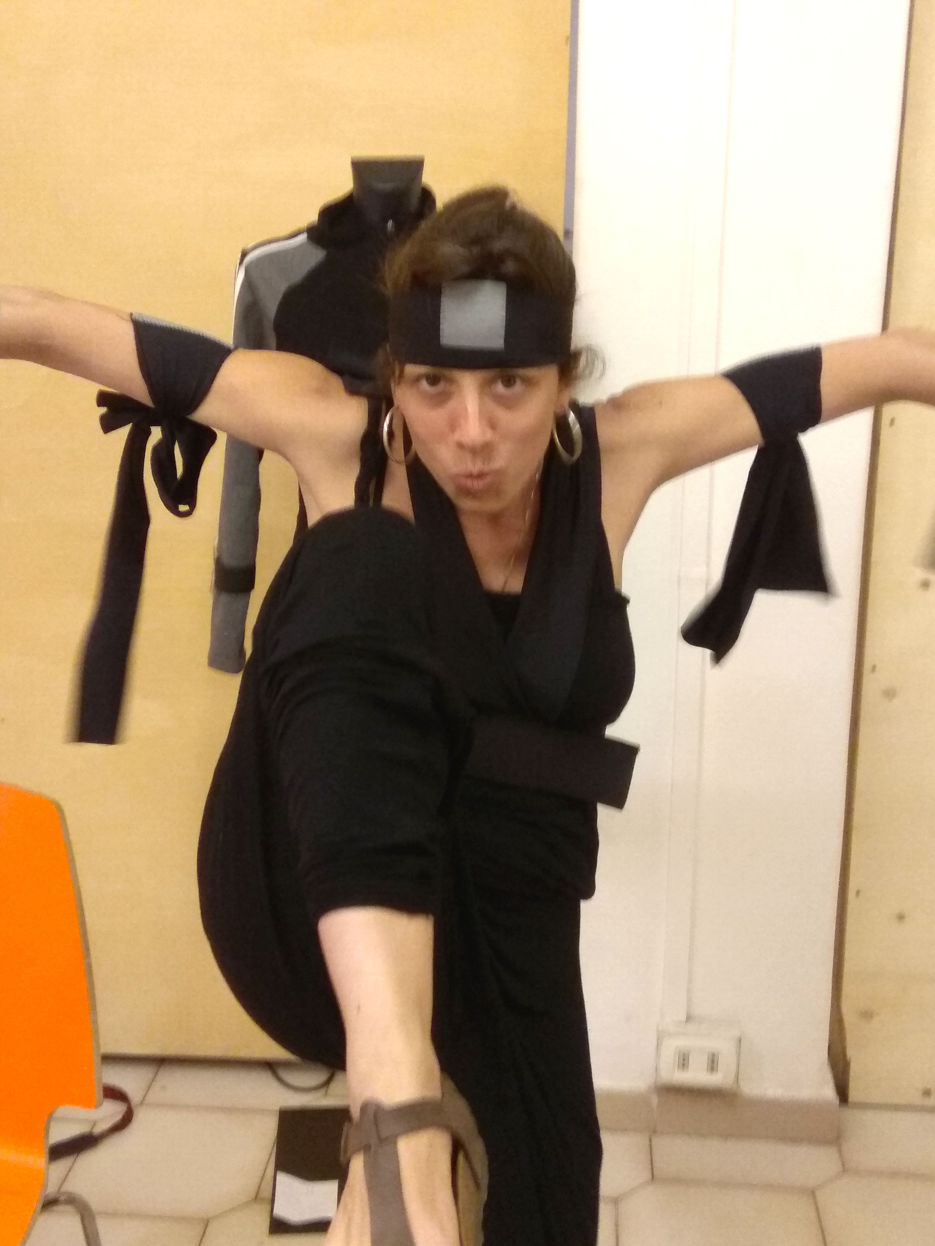
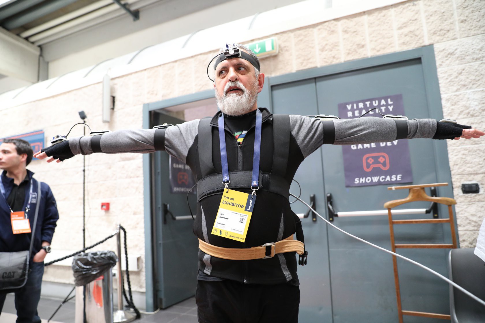
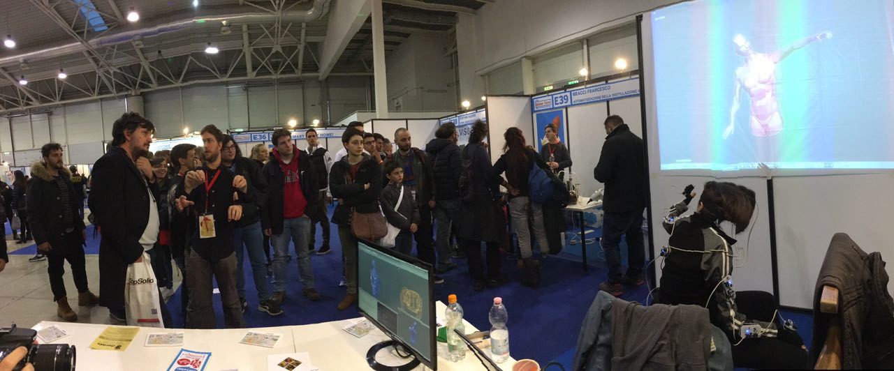
Arianna: a great prototype for an easy low cost DIY sensor attachment suit.
Antonio: networking improvements. SBC as an access point.
Emanuele: 3D modelling in Blender with mocap
Lorenzo and Matteo: Mocap suit as musical controller in Max/MSP
Kine: thanks for soldering all those sensors!
Massimo and Sara: processing SDK foundations. This gives the user a simplified interface to work with the mocap information.
Mauro and Alexia: Mocap suit as a musical controller in a Supercollider
Stefano: Unity 3D integration. Making visuals to go with the music.
Andrea: Some mysterious project (as usual)
We gathered lots of information about bugs, and possible interface improvements!
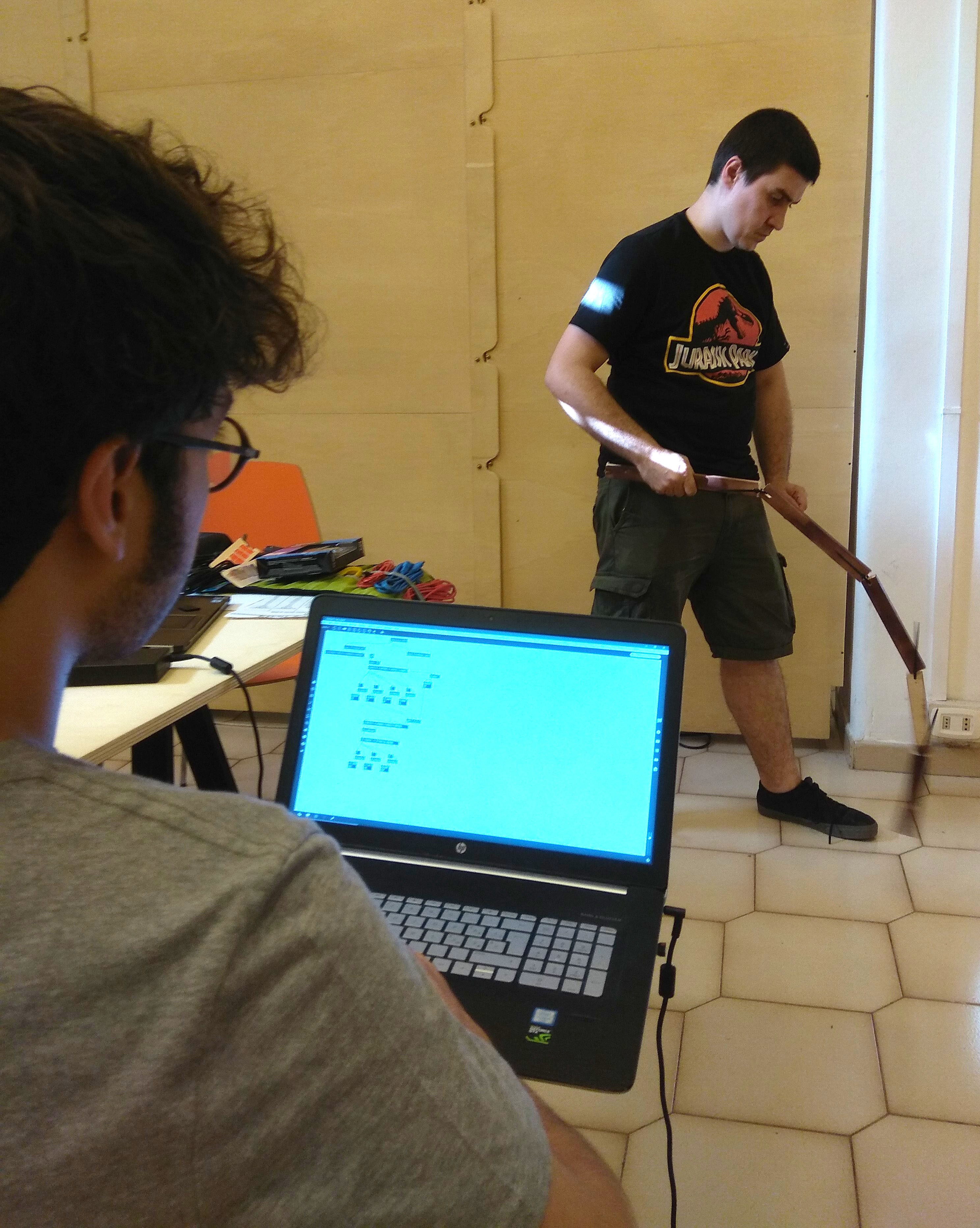
Not to forget, of course... The winner of the hackathon by unanimous decision: Valerio and his dinosaur capturing tail prosthesis!!
![]()
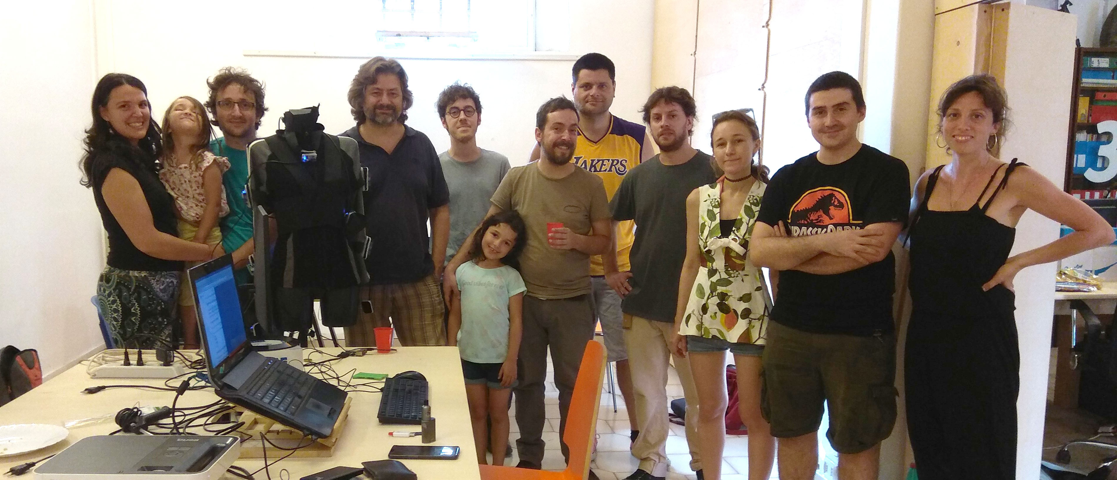
Many thanks to all the partecipants. We had a great time! -
Motion capture Hackathon
07/10/2018 at 15:03 • 0 comments![]()
On July the 21th the first Chordata motion capture Hackathon will take place!
It will be an occasion for users to test the system before the release, and for as to catch some bugs ;).
The idea is bring together performative artists and digital creators to explore the possibilities of mocap as an artistic discipline.
It will take place in Rome, at Workco coworking. If you live somewhere else a stream of capture data will be available to let you work from home!
If you want to participate fill the here, or just leave a comment below.
-
The first release is coming!
05/25/2018 at 17:32 • 0 commentsIn the last months we were working hard to achieve the stability in the capture required in any real world scenario, and to be honest the results are not bad at all. So it’s time now to stop with this “improving stability” direction and focus on making the minimal interface changes in order to release it.
We kept it to ourselves all this time because we felt like there was no sense in publishing a shaky, or hardly usable system. But at this point it would be great to have other hands rather than ours using and testing it, finding bugs or imagining a better user experience.So, we set august 2018 as a first release date. Looking forward to it!
-----
In the meantime we’ve been showcasing in a couple of places:
Mmkm STUDIO @ Open House Roma.
The friends of mmkm studio invited us to present a little performance with dance, music, and live-generated visuals. It was the first time we used the Chordata suit for what it was originally conceived for.. Three years ago!
But it was also the first time the suit was used on a real “stage” in front of other people, having to deliver correct results during a definite period of time, and it went pretty well. This was the kind of proof we needed to convince ourselves that the little bird is ready to leave the nest.
Hope you like it:
For this presentation, and most of the time we are using a 3D model by AlexanderLee, thanks Alexander for sharing it!
Codemotion Rome:
This is one of the most important programmers conference in Europe. It was great to be able to share the guts of the software implementation with so many people, we got tons of interesting opinions and advices.
![]()
We would like to thank Ugo Laurenti and Sara Di Bartolomeo for been there helping out with the stand, and also Flavia Laurencich and Juancho Casañas for the support.
Thanks a lot!
-
Chordata @ Maker Faire Rome 17
12/11/2017 at 20:32 • 0 commentsIt's been a while since I don't post any update here.
Last month we were very busy in the making of a better looking prototype to be shown on this year edition of the Maker Faire, here in Rome.This new prototype really shows the potentialities of the system, even tough several adjustments and calibration procedures should be still implemented.
Public's response was really positive and several people showed interest in accessing to a cheap and hackerable mocap system. This response convinces us on putting more effort on its development.
We also received some exciting collaboration proposals so perhaps we'll have some interesting announcements to make on the incoming weeks.Stay tuned..
![]()
-
Hands on the second physical prototype
11/09/2017 at 18:22 • 0 comments![]()
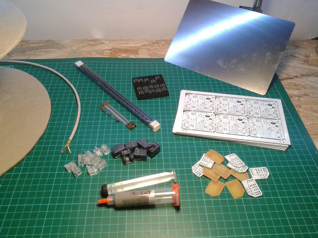
I finally have all the parts to start building a second and more complete version of the system. The PCBs, stencil, and components were already arrived some time ago, but the solder paste kept me waiting for a long time, if you want to hear the whole story, please refer to The solder paste odyssey.
If everything goes right I should be able to build at least twelve of the sensor nodes, and arrange my first whole-body capturing suit.
The problem: apart from the general refactoring that I’m performing on the code, I will have to implement the lecture of the LSM9DS1 instead of the LSM9DS0 from the previous board. Fortunately sparkfun offers a library for arduino, which can be easily adapted to this system
The real problem: home soldering 12 of these units with their tiny LGA packages, represents 12 one-shot opportunities... of getting it wrong.
-
Refactoring the PCB
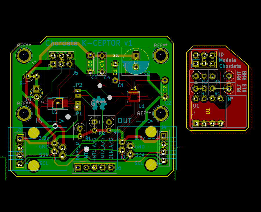
10/19/2017 at 19:14 • 0 commentsAs I said, it was time to make a second version of the PCB in order to be able to build a complete body suit. I’ve called it “K-Ceptor” (Kinetic perCEPTOR).
The changes are detailed on the previous log entry, and listed here:- Changed the LSM9DS0 for the LSM9DS1
- Added an address translator and removed multiplexer
- RJ-12 connector for both input and output (or optionally solder a regular 2,45mm header)
- An EEPROM memory
![]()
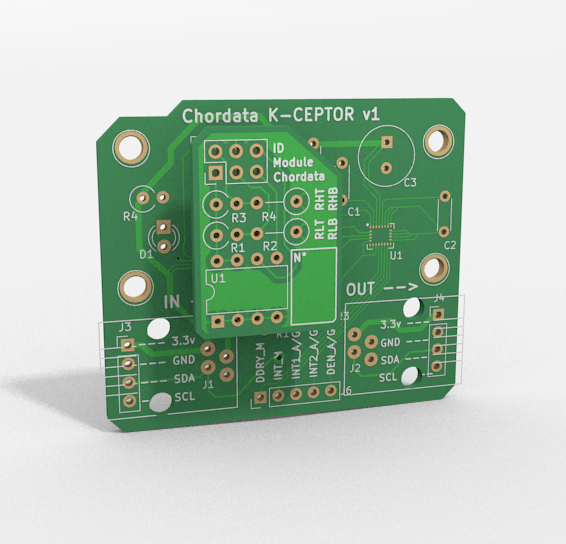
One thing that I hadn’t planned for (it came out while I was making this new pcb) was to arrange some of the components on a separate board: the “id_module”.
This module is a tiny, one-layered pcb, containing the EEPROM, some resistors to setup the translation value of the LTC4316 (i2c address translator).
This separation allows for greater flexibility and hardware resources reutilization. For example, suppose some user has a complete suit and, at some point, he is using it for two different activities taking place in different environments, namely: a capture for an animation performed outdoors and the rehearsals of a live performance in a theater. Since the electromagnetic interference on each location is completely different, the ideal would be to perform a calibration* on each sensor at least once for each place. Having a duplicate set of cheap id_modules would allow the user to easily apply the corresponding calibration before each use.
(*) again: I'm talking about the sensor calibration, not to be confused with the pose calibration which should be performed before every capture.
![]()
A render of the id_module stacked in position, on top of the K-Ceptor.
-
Current situation and ongoing work
10/03/2017 at 09:04 • 0 commentsHere's a video showing the current state of the capture. This 3 sensor prototype it's with what I've been working on in the last months, even if it's not as spectacular as a whole body capturing suit, it allowed me to easy test the features as they were implemented.
The focus on this part of the development was put on:
- General stability of the program.
- Capability for reading sensors arranged on any arbitrary disposition (or hierarchy).
- Obtaining readings of each of the sensors at a regular interval, no matter in which part of the hierarchy it was.
- Capability for reading a single sensor on the hierarchy, process it's raw data and generate calibration information. Dump this information to a file.
- Implementing a correction step for each sensor, with data obtained on a previously done calibration, before the sensor fusion.
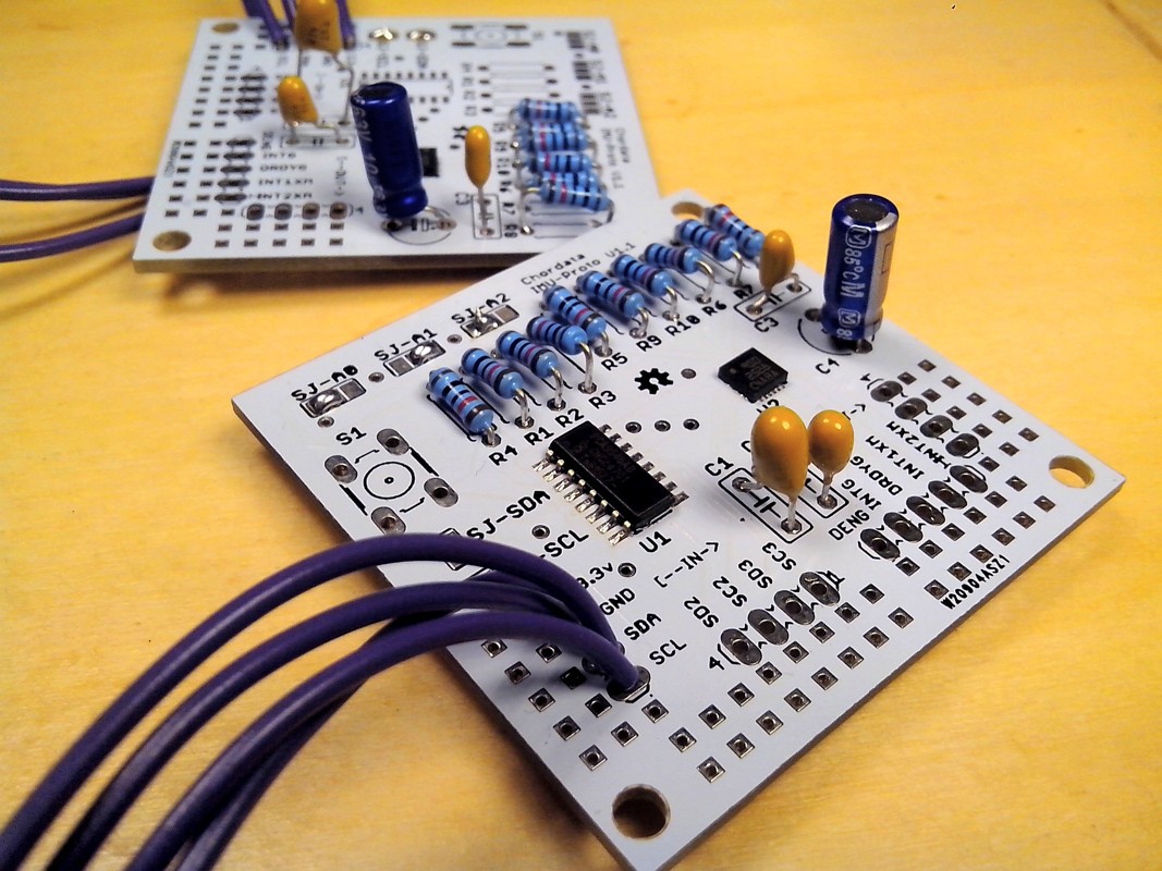
The Imu-Proto sensor unit,
physical base of the prototype is simple pcb featuring a IMU sensor, and an i2c multiplexer. The idea was that this units should be easily interconnected allowing the creation of tree shaped hierarchies. So it had a 4 pin input and output carrying the current, and the i2c bus. It also exposed pins for the secondary gates of the multiplexer.
![]()
This arrangement was great for testing, but now I'm working on the creation of more user-friendly version of the sensing unit, which will have the following features:
- -Lack of a multiplexer which will be on a separate unit, and instead implement an address translator.
The multiplexer works fine, but it wasn't really used on all nodes, in the other hand it added unnecessary overhead to the bus, having to switch it for each sensor before the reading. Instead having it on a separate unit will allow a more flexible creation of arbitrary trees.
- An easy pluggable connector.
Of course, having to solder 4 wires in order to create the suit wasn't flexible at all. This connector should allow the performer to freely move while keeping the connection stable, should be cheap and common, and not excessively bulky. At the moment I'll go with the RJ-12 connector (the one regular telephones use).
- An on-board memory.
The main function of this memory will be storing the sensor calibration data. This calibration should only be performed once in a while*, and until now the generated data was stored on a file in the Hub, not allowing a particular sensor to change Hub, or position on the hierarchy.
(*) I'm talking about the sensor calibration, not to be confused with the pose calibration which should be performed before every capture.
Motion Capture system that you can build yourself
An open hardware-software framework based on inertial sensors that anyone can use to build a human motion capture system.