Close
0%
0%

40-way Ethernet Digital I/O extension for Loxone

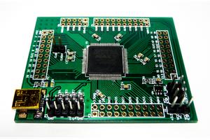
Low cost 40 way digital I/O board, used to extend available IO to the loxone miniserver. Based on teensy 2.0 ++

Similar projects worth following
This project shows how to build a low cost reliable 40-way digital input or output board- designed to integrate with the loxone mini-server. This was needed as our project needed over 200 digital I/O's and to do this using loxone extensions would use too much space and money!

I've nearly completed building my own home, and have used the loxone mini-server to supply the home automation.  When specifying the server, we quickly realised we would have to find another solution for all the digital io.   
We have 43 light switches - but each light switch has 4 contacts - making 172 inputs just for the light switches.  Add to that 20 door & window sensors, plus blind controls, PIR sensors, under floor heating actuators and pumps.  You get the idea.
I chose the teensy 2.0++ as it had a large number of digital IO on the board.  We did consider using I2C io extension boards, but physical size is a factor and it was easier for us to make it compact using the teensy.
I'm not a hardware expert at all!  But the system we have made is bullet proof reliable.  The software and interface to the loxone does not use any polling at all- so all the double/triple clicks work flawlessly with the loxone system.
The boards have a web interface which is really important for setting up and diagnostics as you have feedback showing which inputs or outputs are active.

In our build we have 2 sub-boards each with 4 nodes - making a total of 8 nodes with a capacity for 320 i/o.  Each sub board has it's own 5v 5 port switch, and a POE splitter - the whole board being run by 1 port on my POE switch.

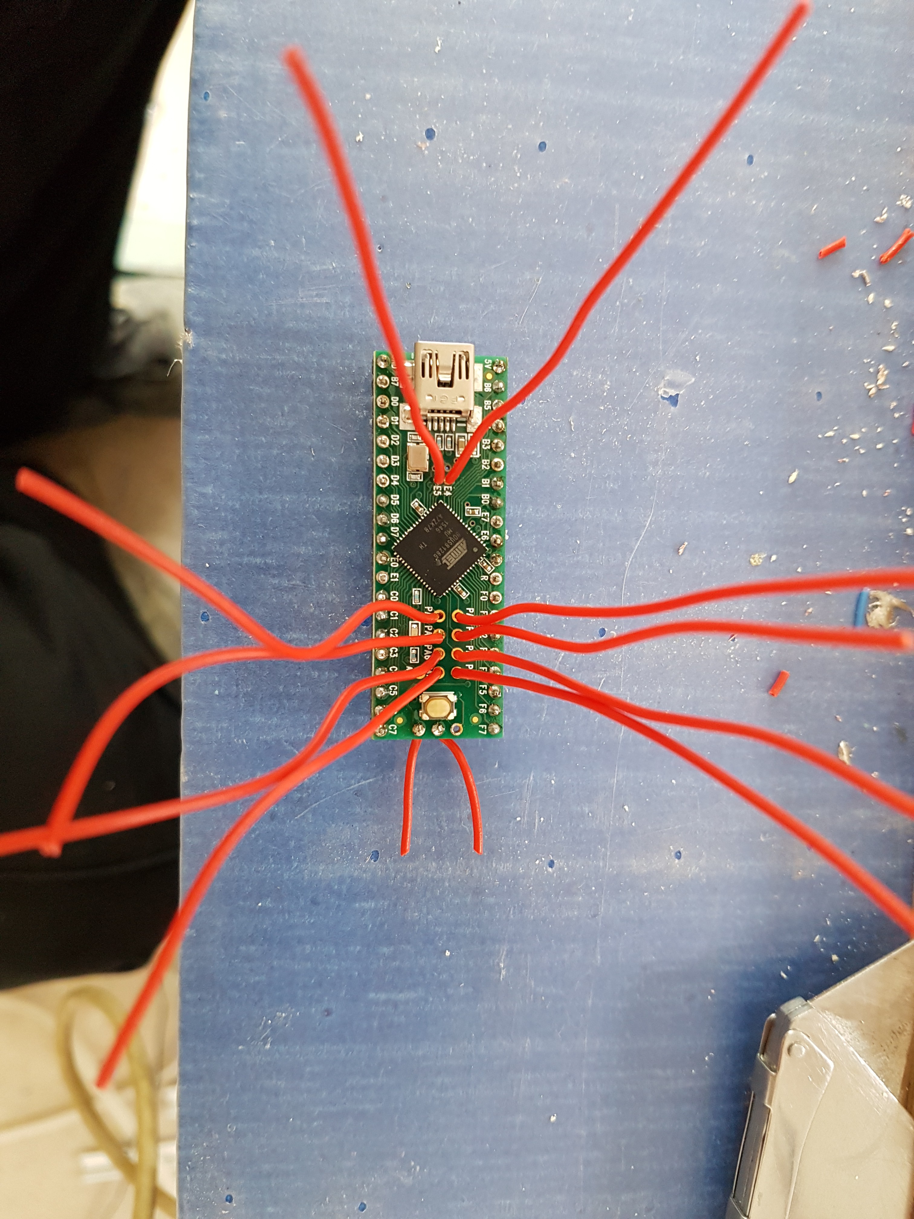
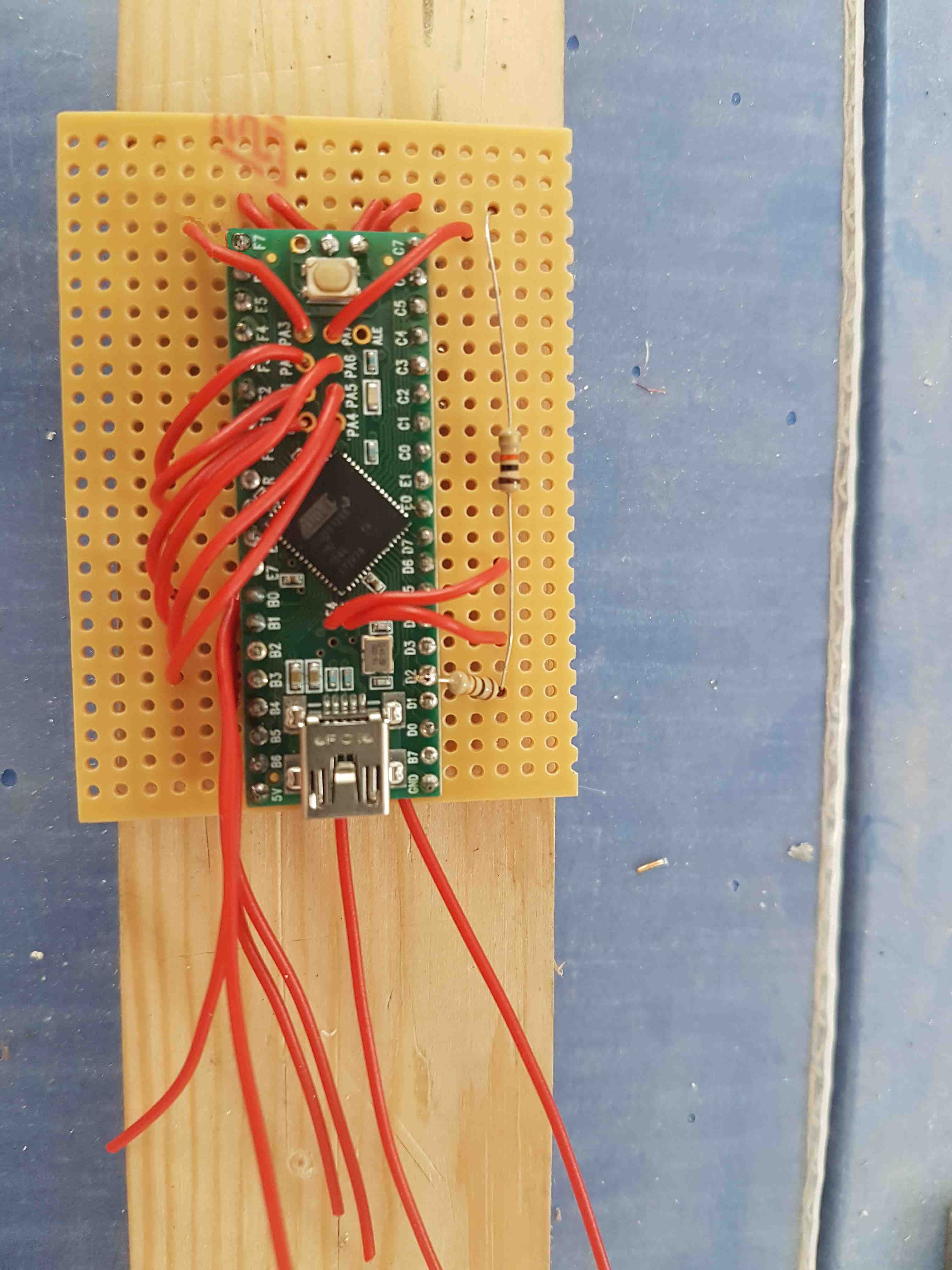
It was a challenge to get 40 I/O available on the teensy 2.0.  We needed 4 pins for the ethernet connection & 1 pin for the on-board LED.  Using the teensy's interior pins, and re-purposing one of the UART pins we were able to have 40 pins usable for io.  The UART pin needed an external pull-up resistor to make it usable for normal io.
teensy_switch_2.zip

Arduino teensy++ 2.0 source code

x-zip-compressed - 18.17 kB - 05/30/2020 at 10:04

Download

DigitalIOCase.skp

Sketchup model for the frame mount

SSEYO Koan Play File - 109.65 kB - 10/21/2017 at 10:14

Download

DigitalIOCase.stl

STL model for the frame mount

Standard Tesselated Geometry - 56.72 kB - 10/21/2017 at 10:14

Download

View project log

  • 1
    Prepare vero board

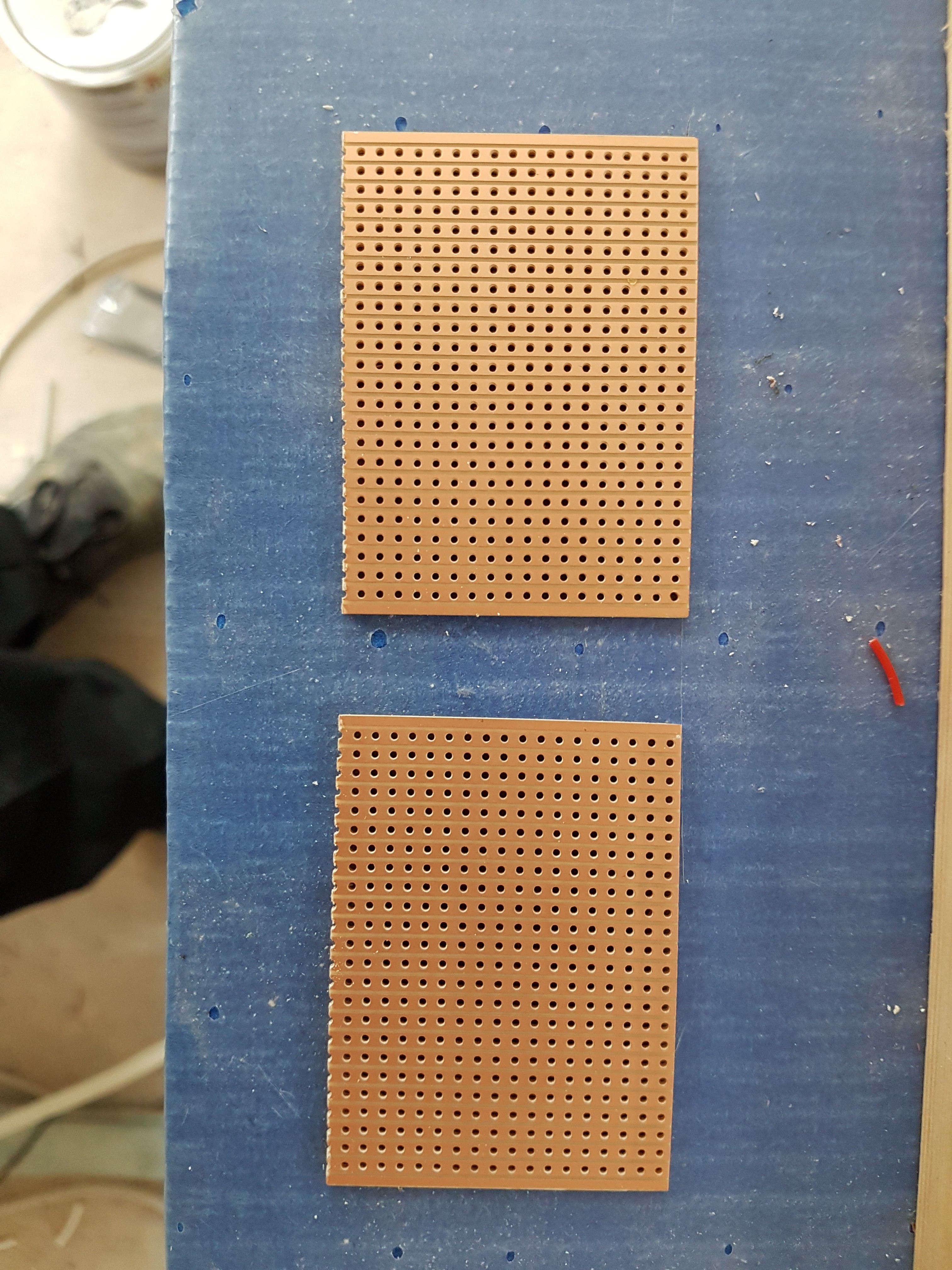
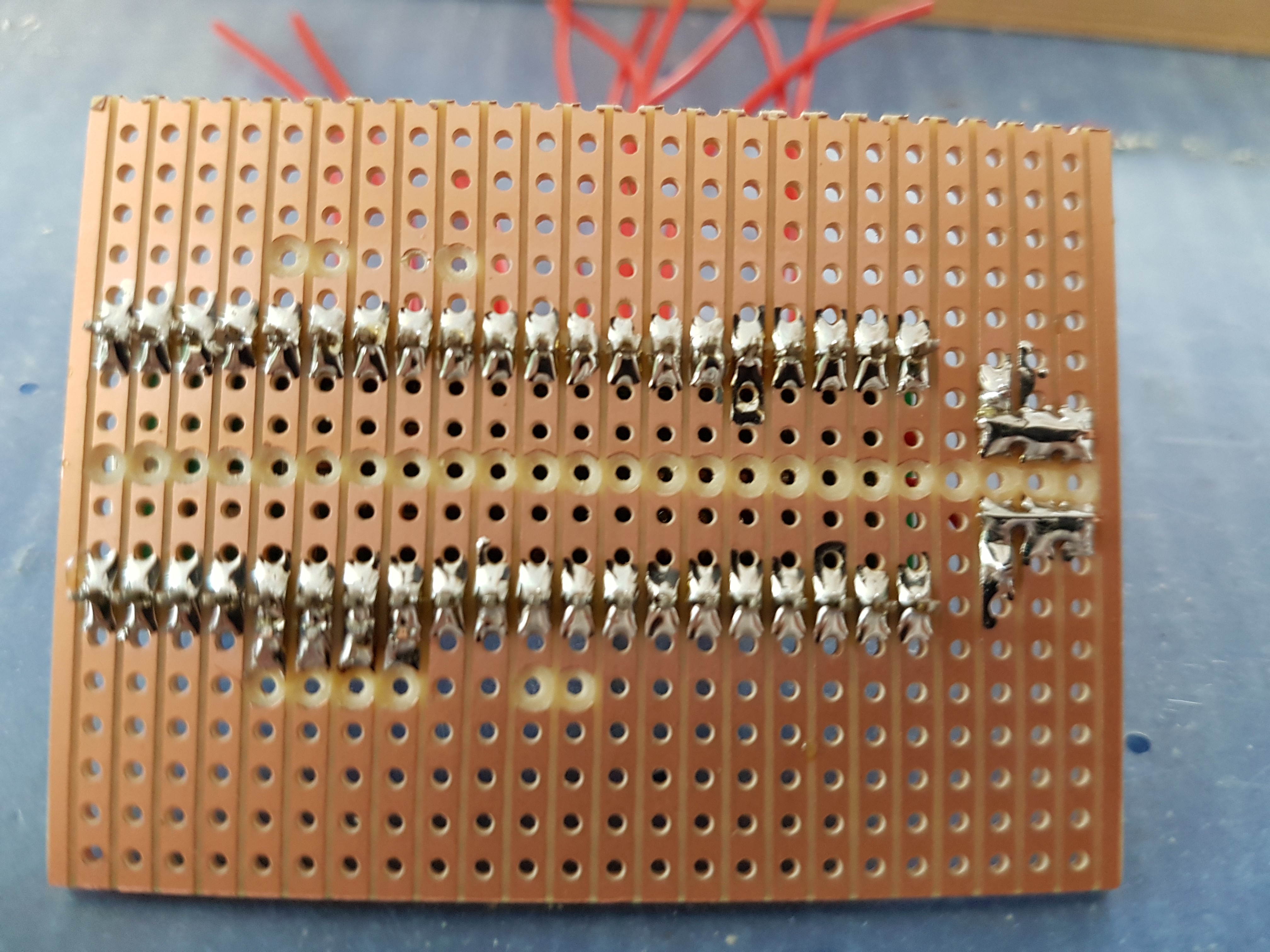
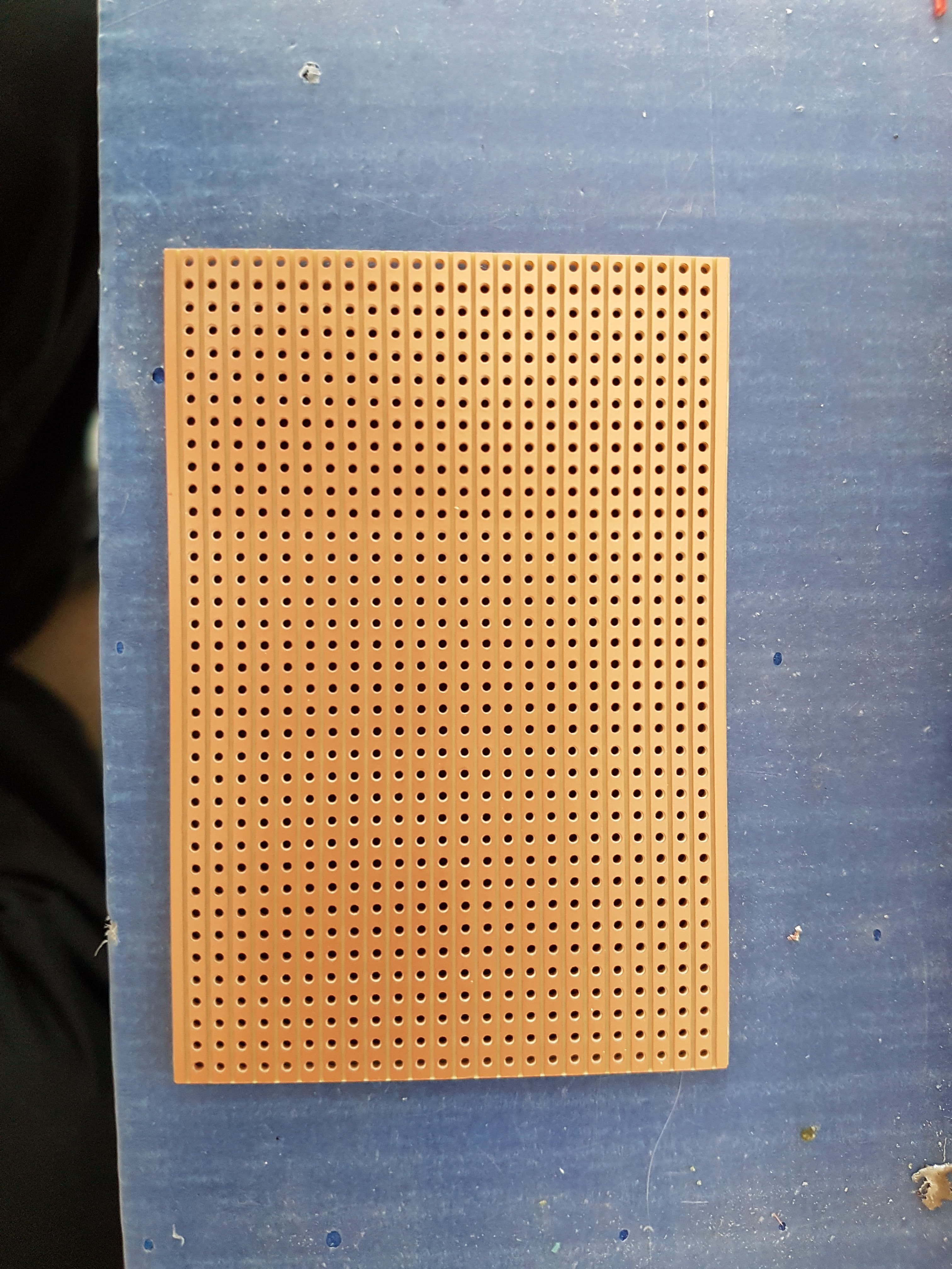
    A standard size vero board can be cut in half to make 2 digital IO nodes.

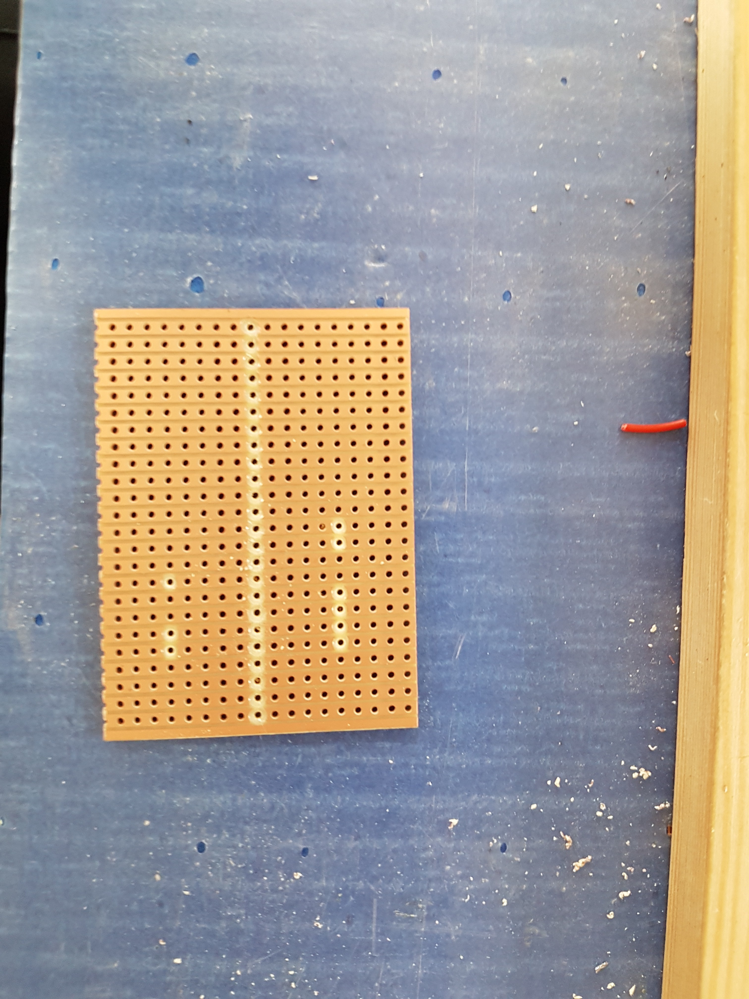
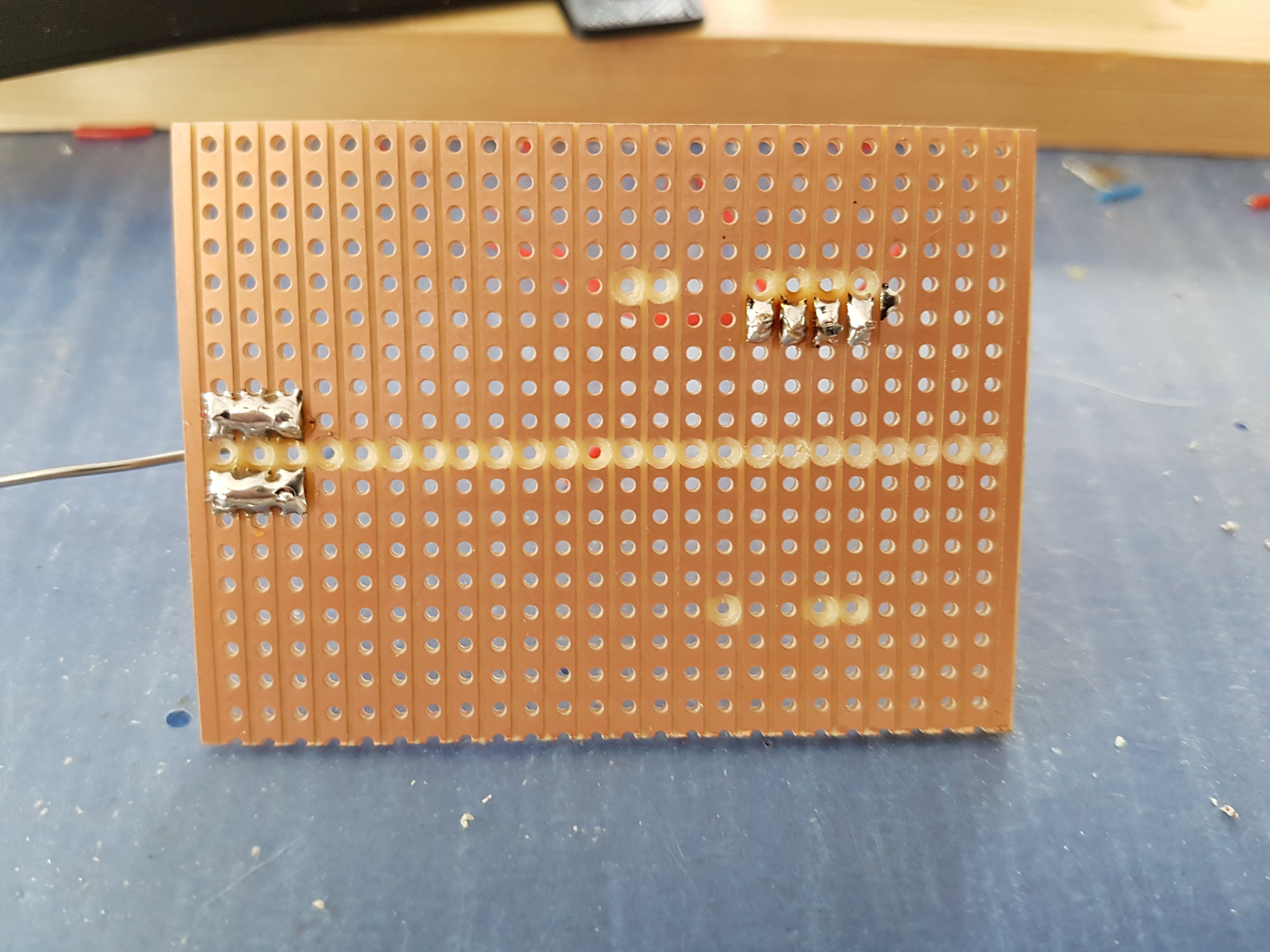
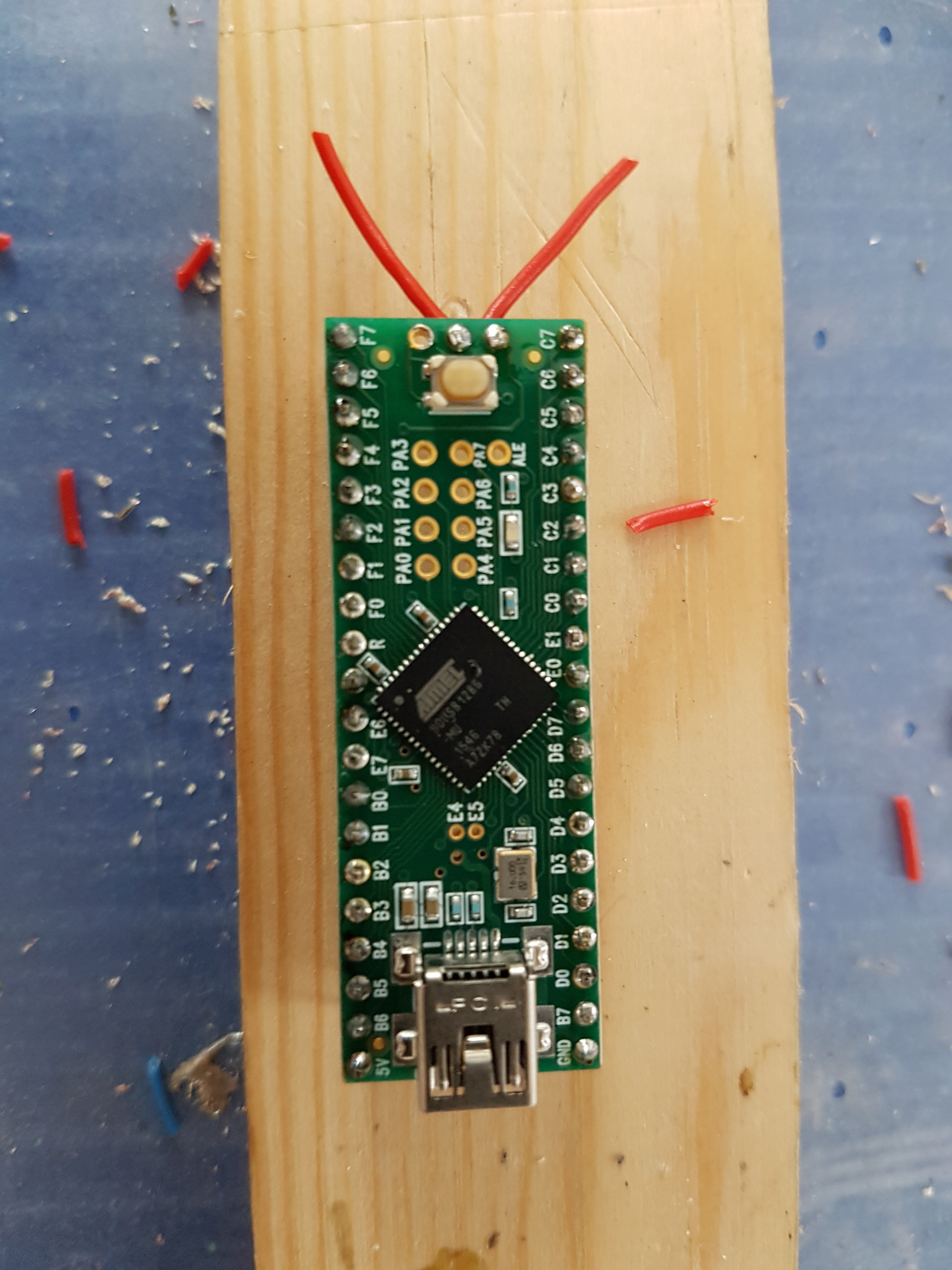
    And I used a drill bit to cut the tracks.  These are for the 9 pins that need to be re-routed as they are not used directly as IO pins (apart from the 1 UART pin that needs the pull up resistor added).

  • 2
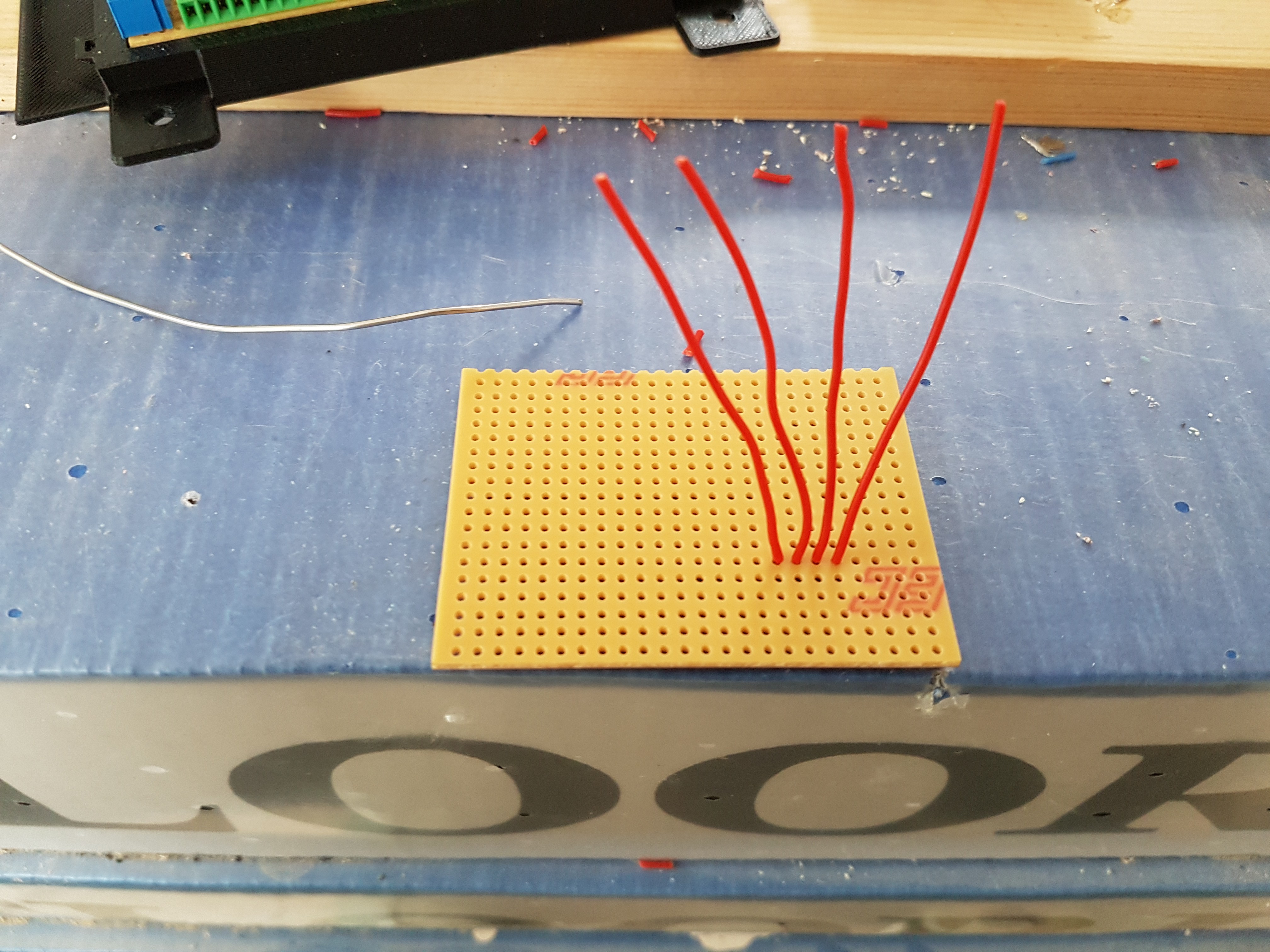
    Prepare the teensy & vero board
  • 3
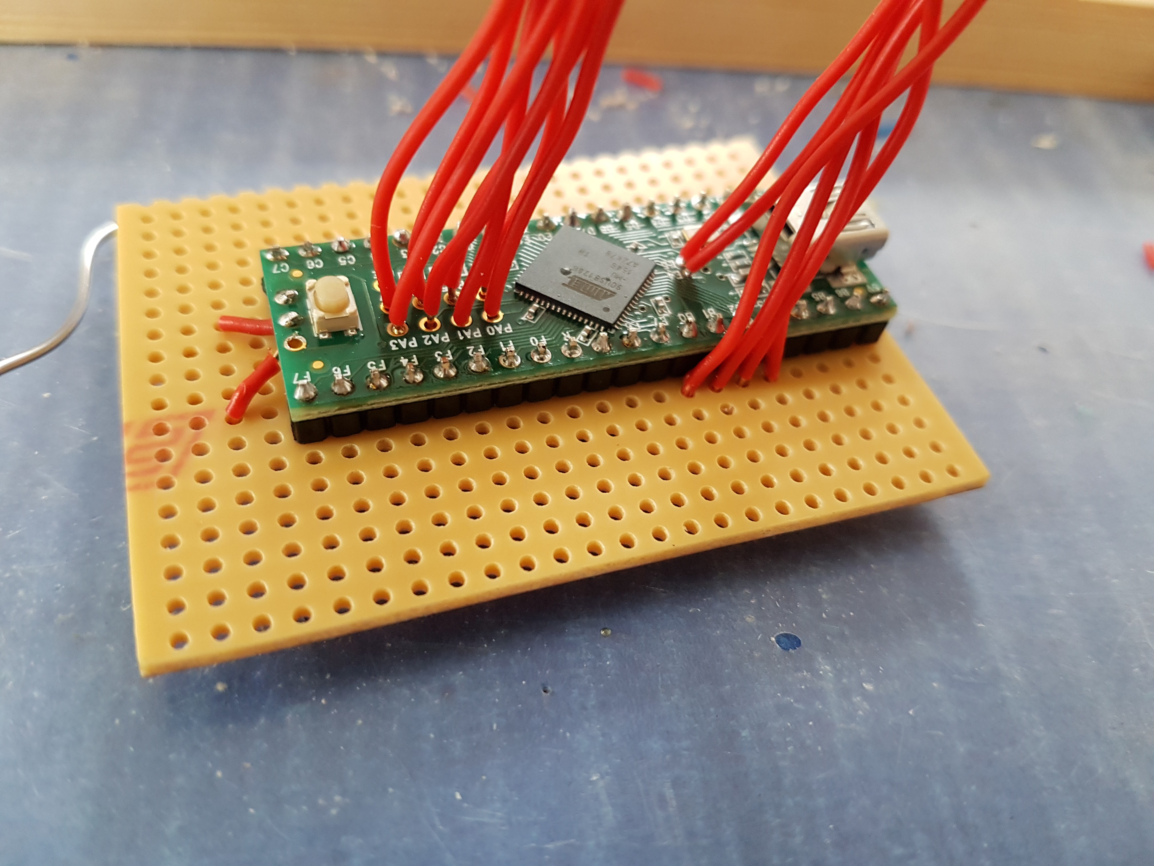
    Mount the teensy on the board

    And add the pull-up resistors

View all 5 instructions

Enjoy this project?

Share

Discussions

christofplay wrote 11/15/2021 at 22:22 point

Hi. What wersion of Arduino IDE did you used? I have compilation error for Teensy ++2 board.

  Are you sure? yes | no

tejush44 wrote 04/13/2021 at 09:51 point

Hi, this is teju from wiznet india, This project is very impressive, if u dont mind we have created our wiznet maker site so wanted to post ur project in that site.

  Are you sure? yes | no

andrew.crockford wrote 11/15/2021 at 18:34 point

Sorry for the long delay for my reply. But, yes absolutely please add this project to your site. Let me know if there's anything else you need. Ta 

  Are you sure? yes | no

Similar Projects

Does this project spark your interest?

Become a member to follow this project and never miss any updates