-
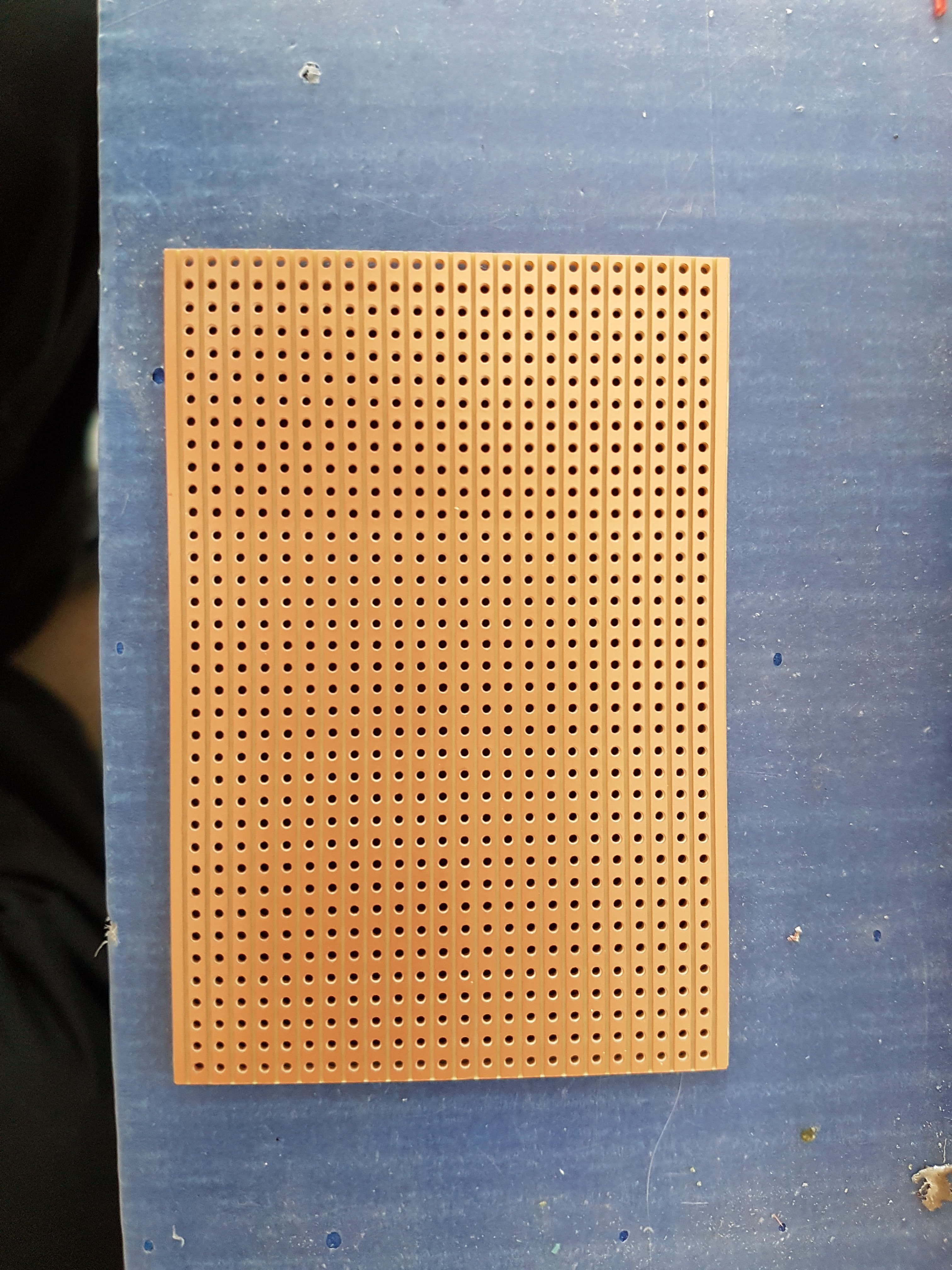
1Prepare vero board
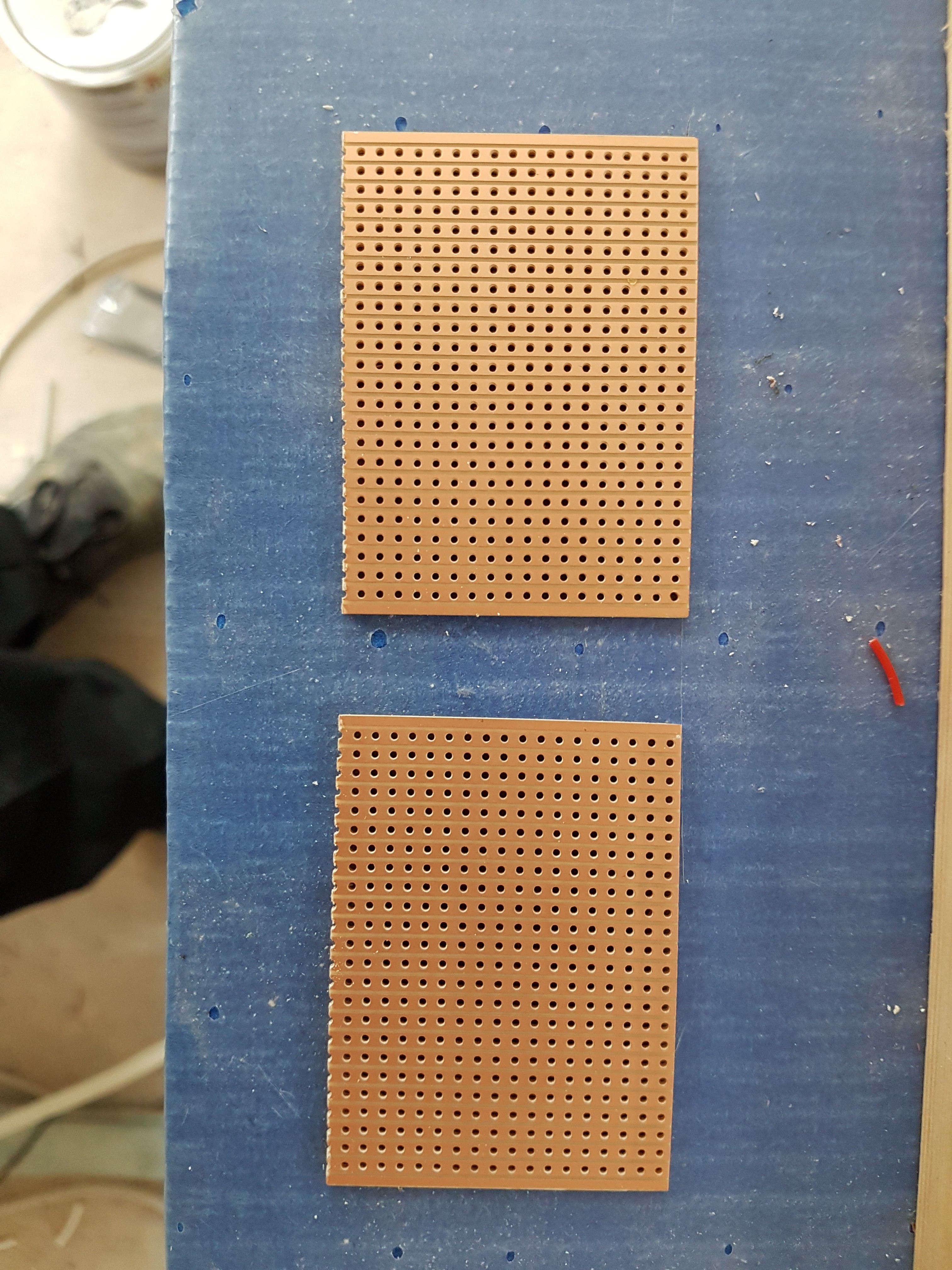
A standard size vero board can be cut in half to make 2 digital IO nodes.
![]()
![]()
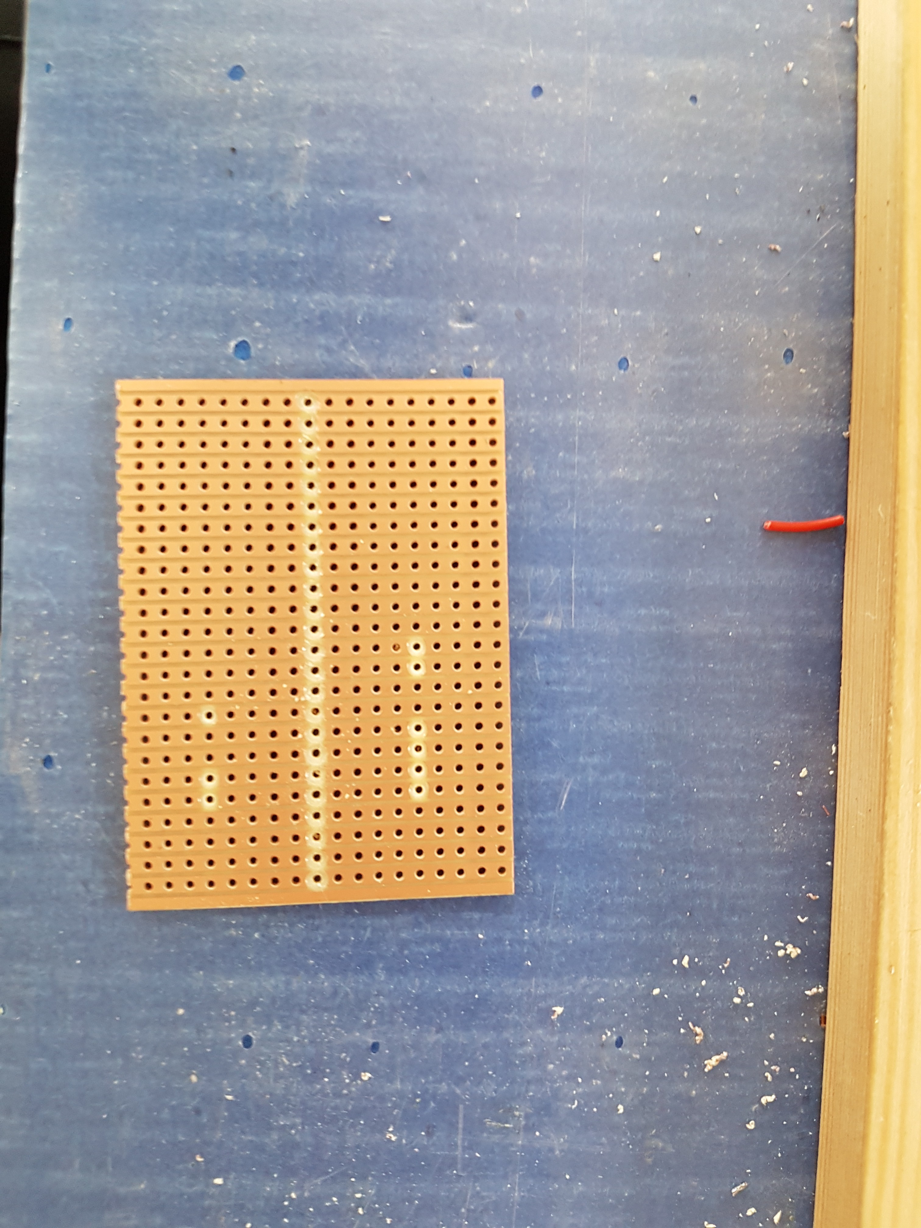
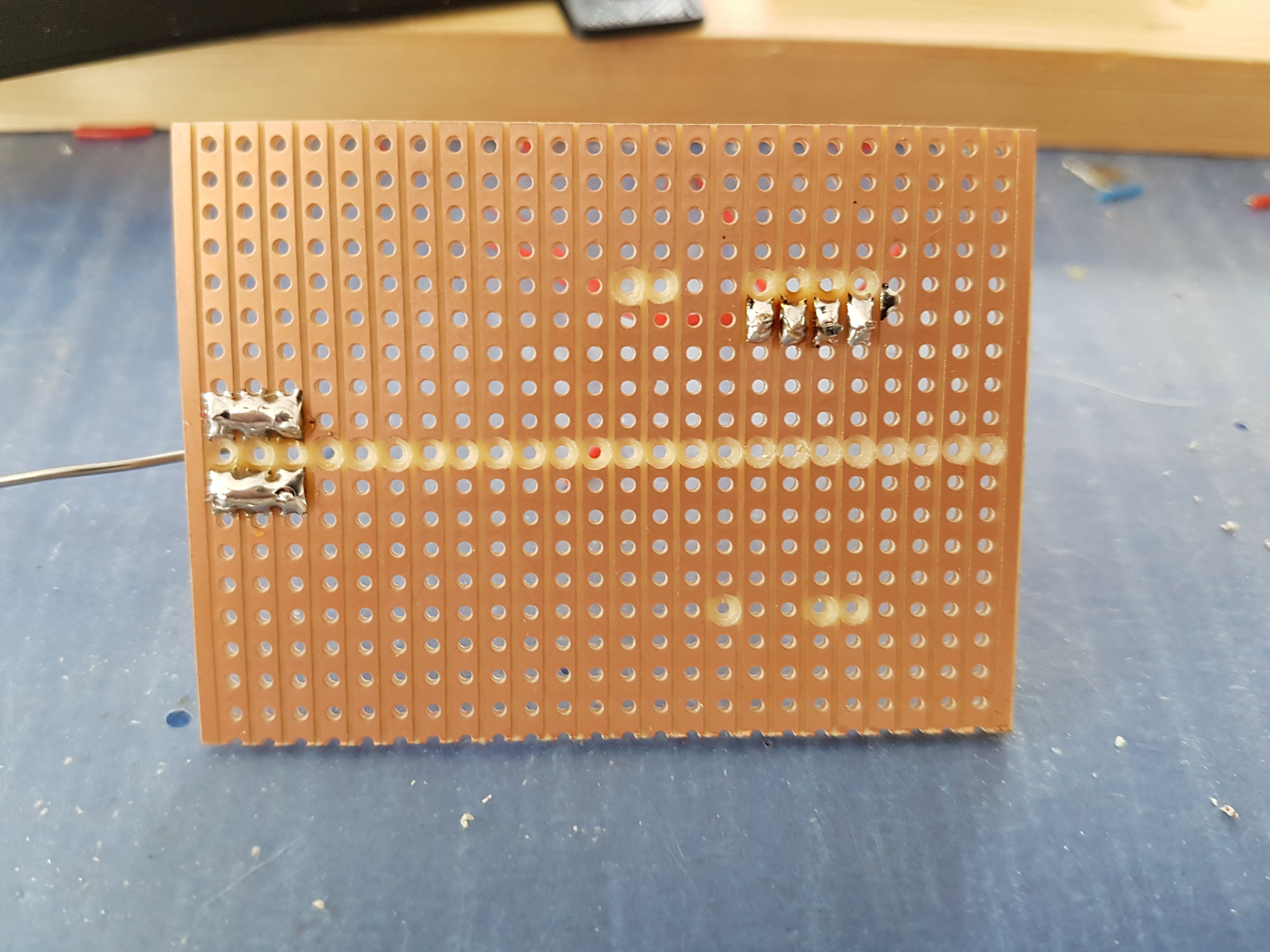
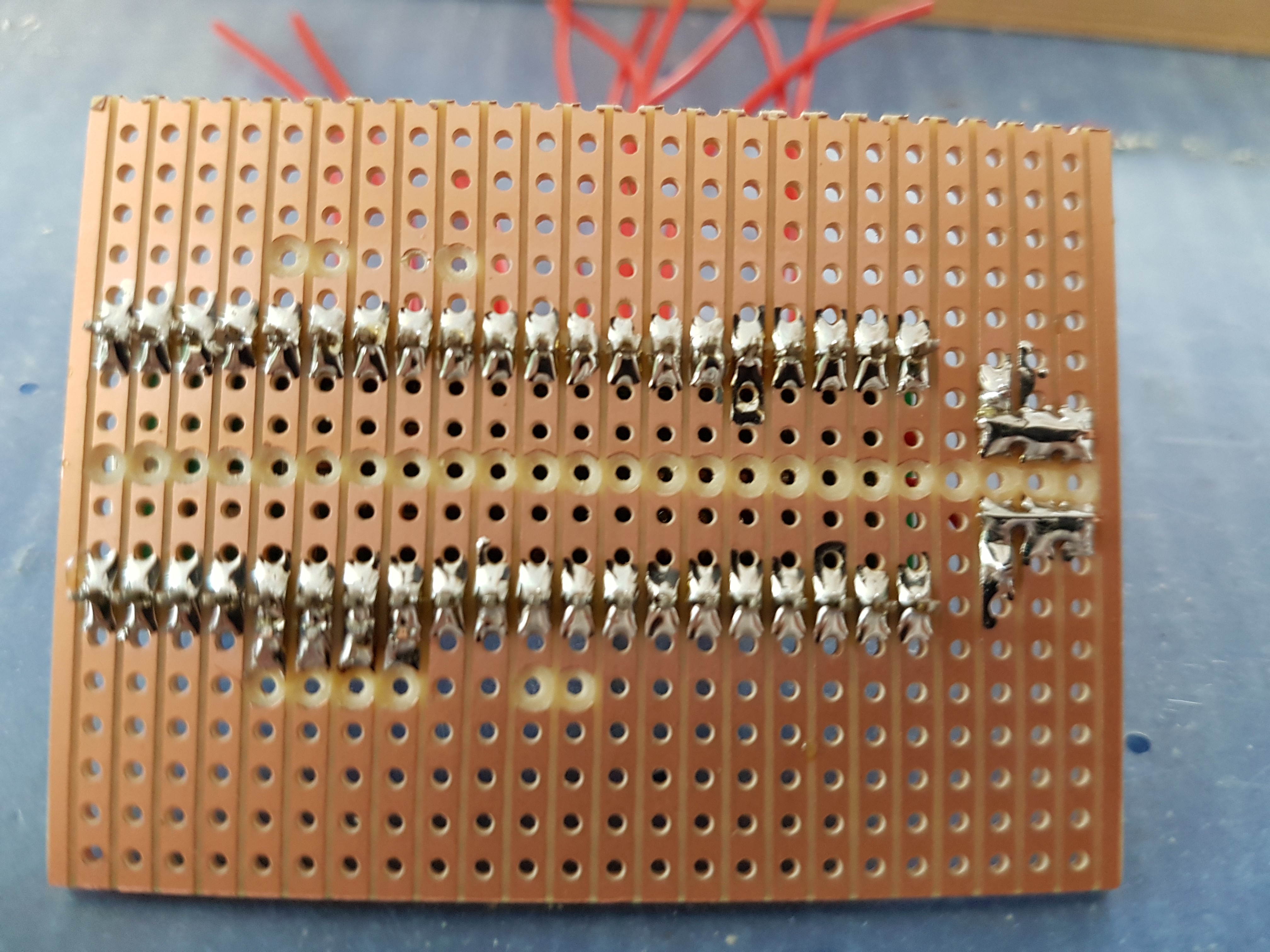
And I used a drill bit to cut the tracks. These are for the 9 pins that need to be re-routed as they are not used directly as IO pins (apart from the 1 UART pin that needs the pull up resistor added).
![]()
-
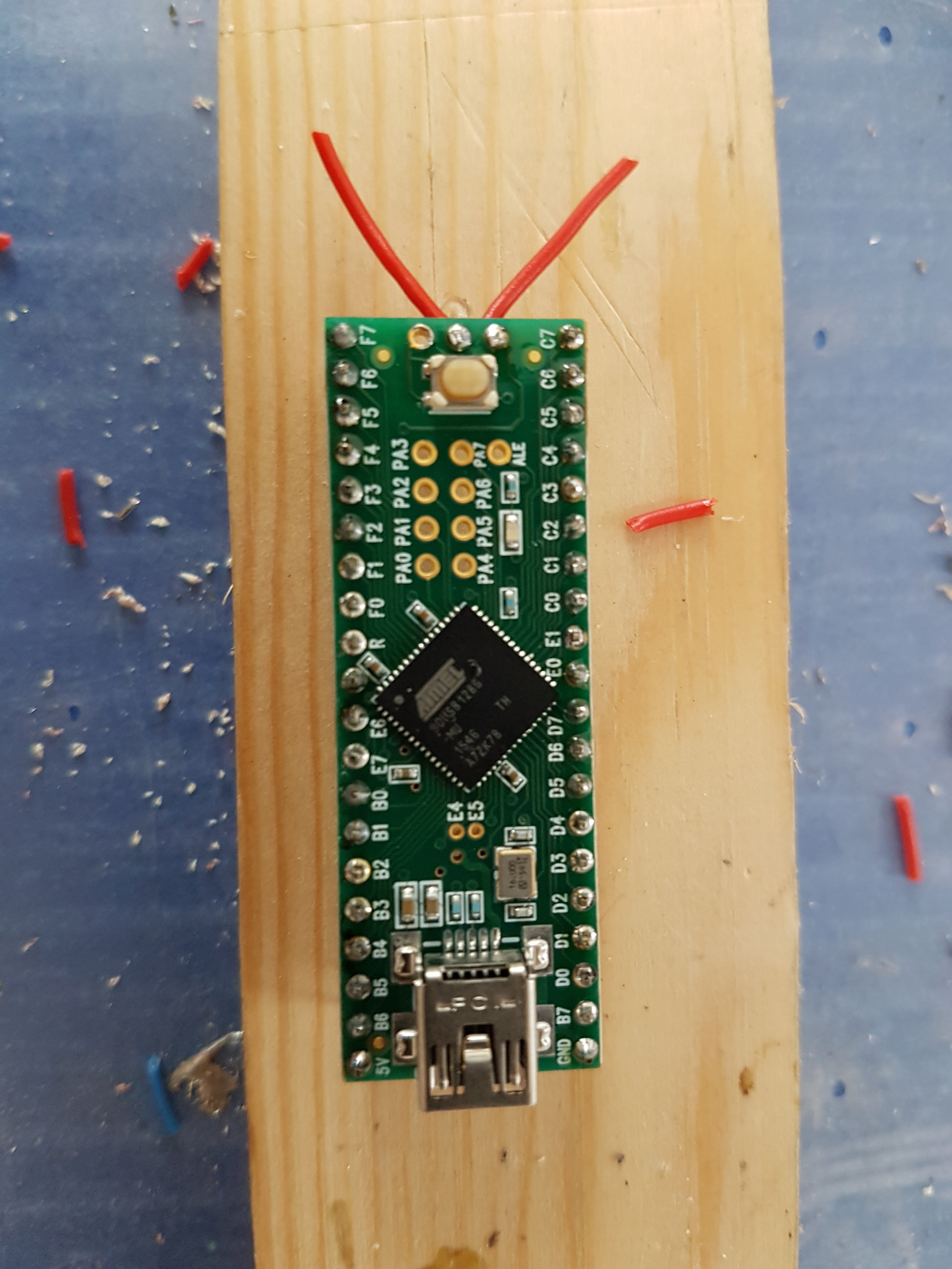
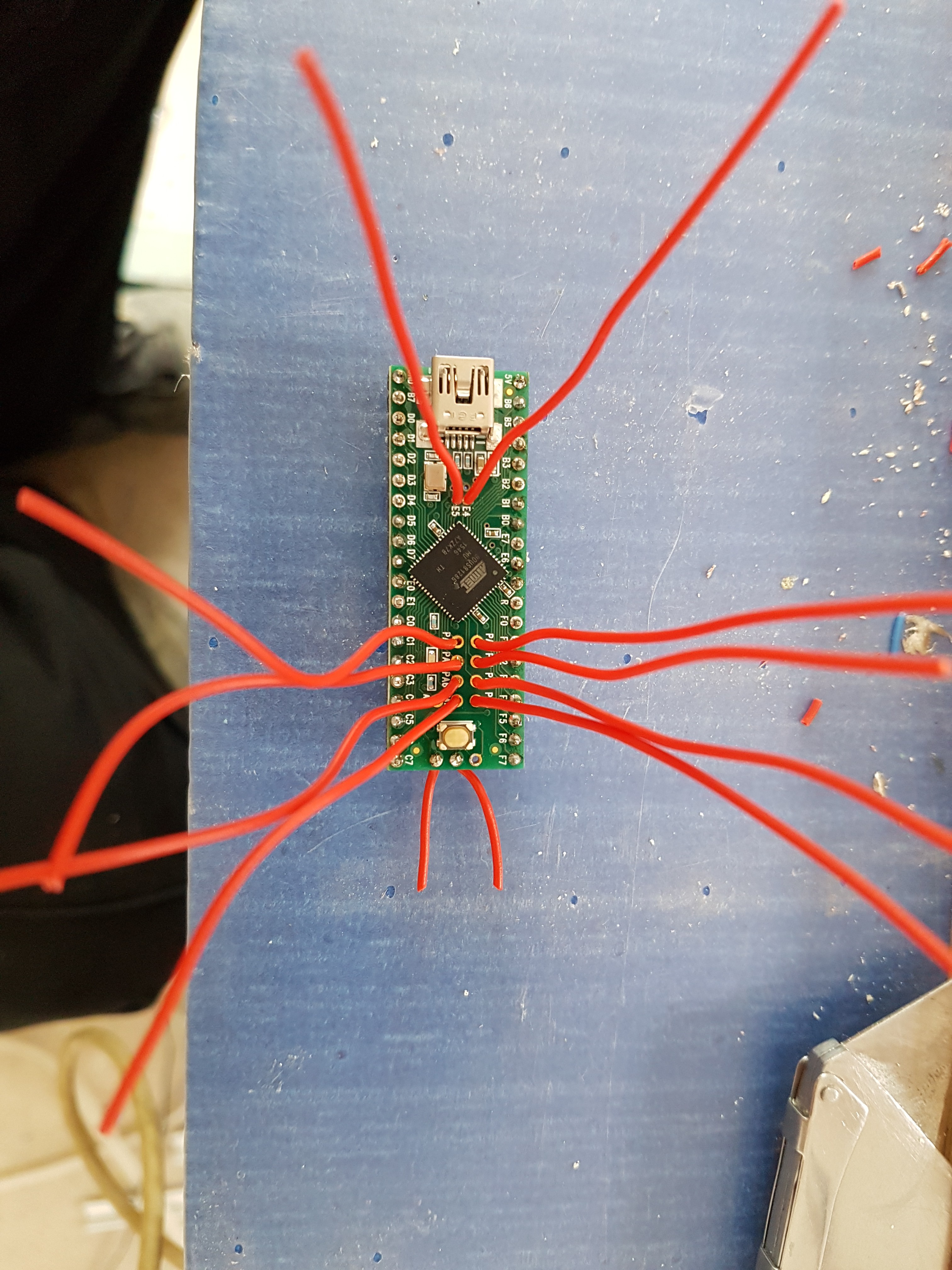
2Prepare the teensy & vero board
![]()
![]()
![]()
![]()
-
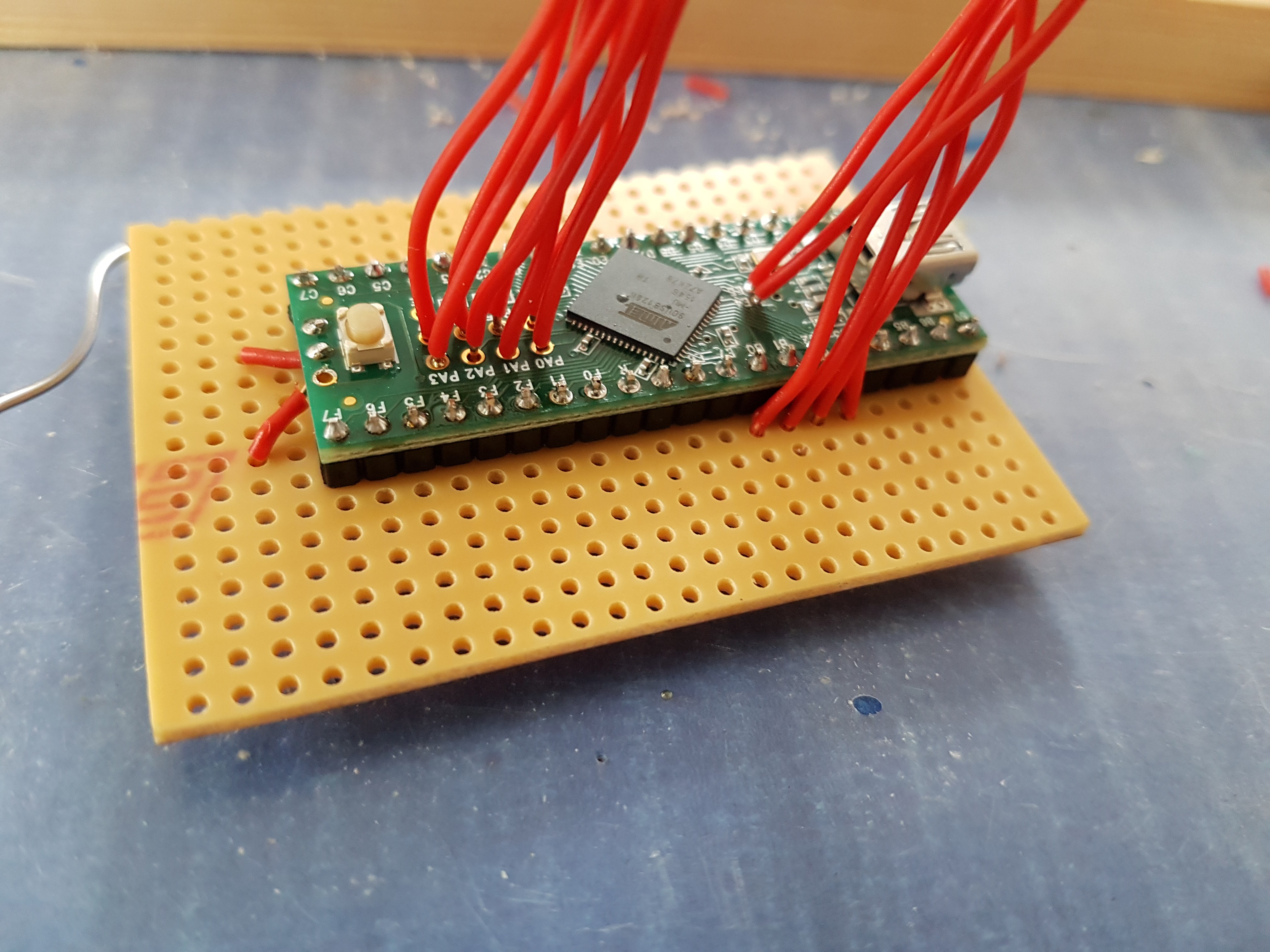
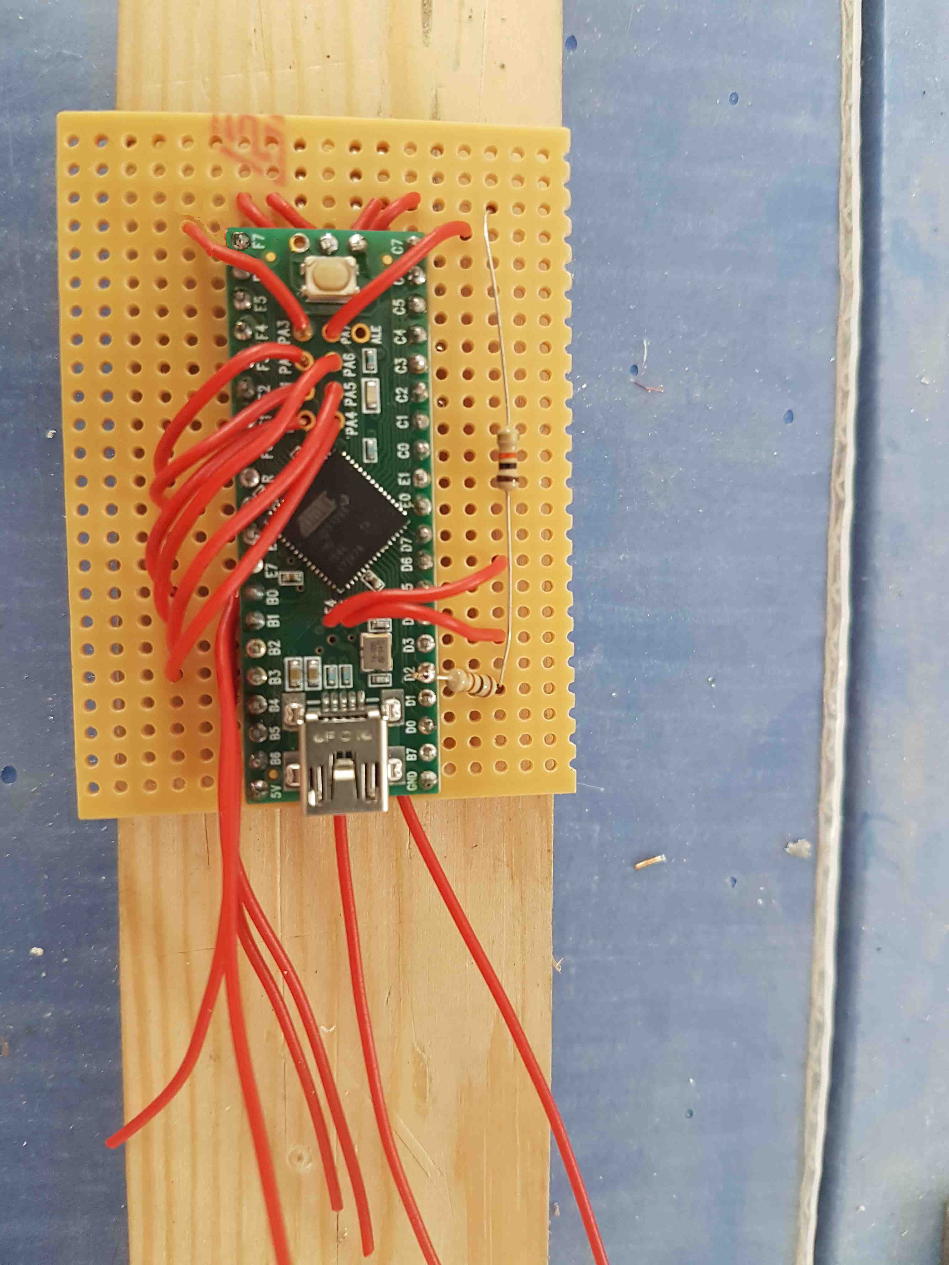
3Mount the teensy on the board
![]()
![]()
And add the pull-up resistors
![]()
-
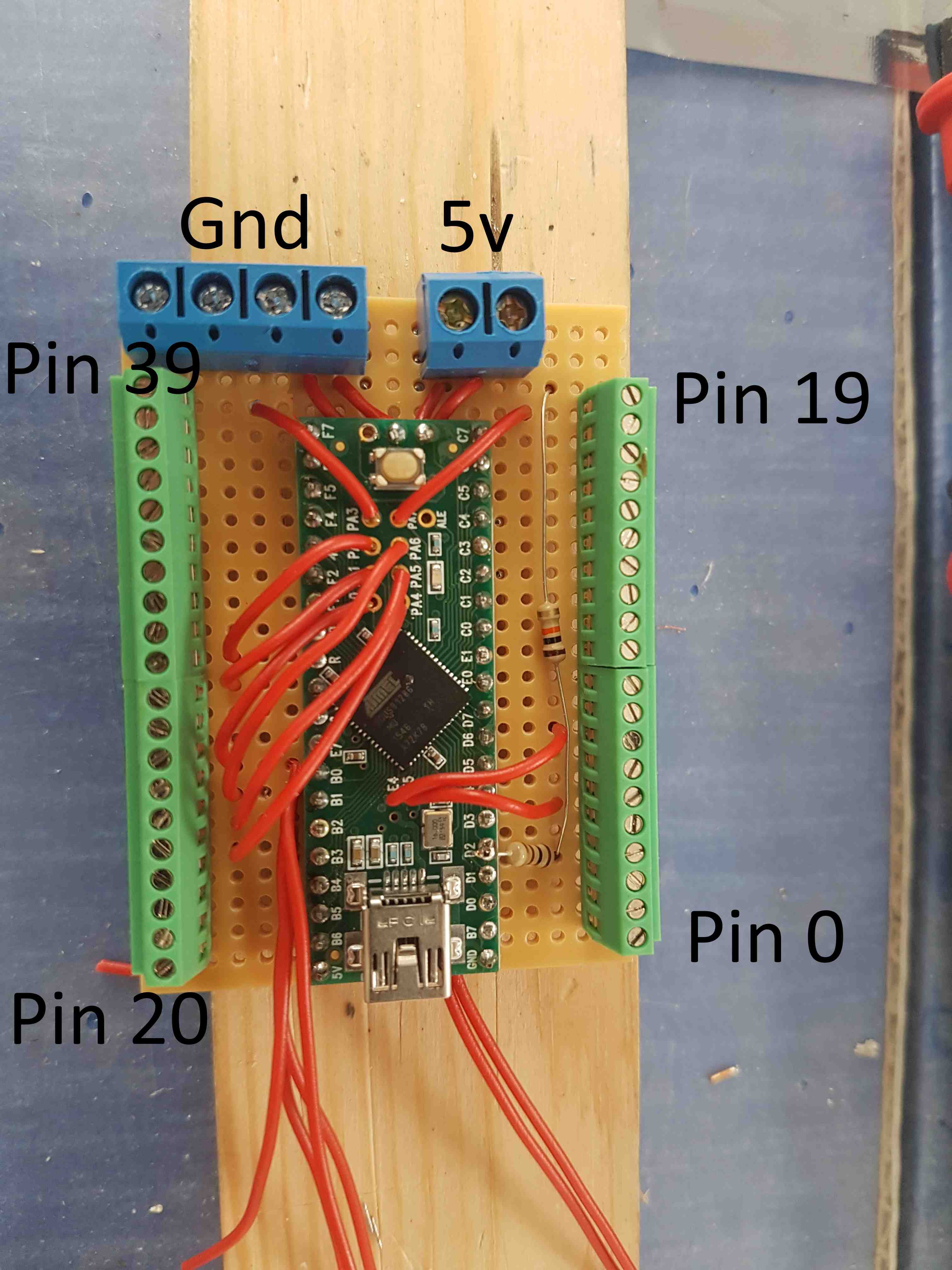
4Add the terminal blocks
![]()
-
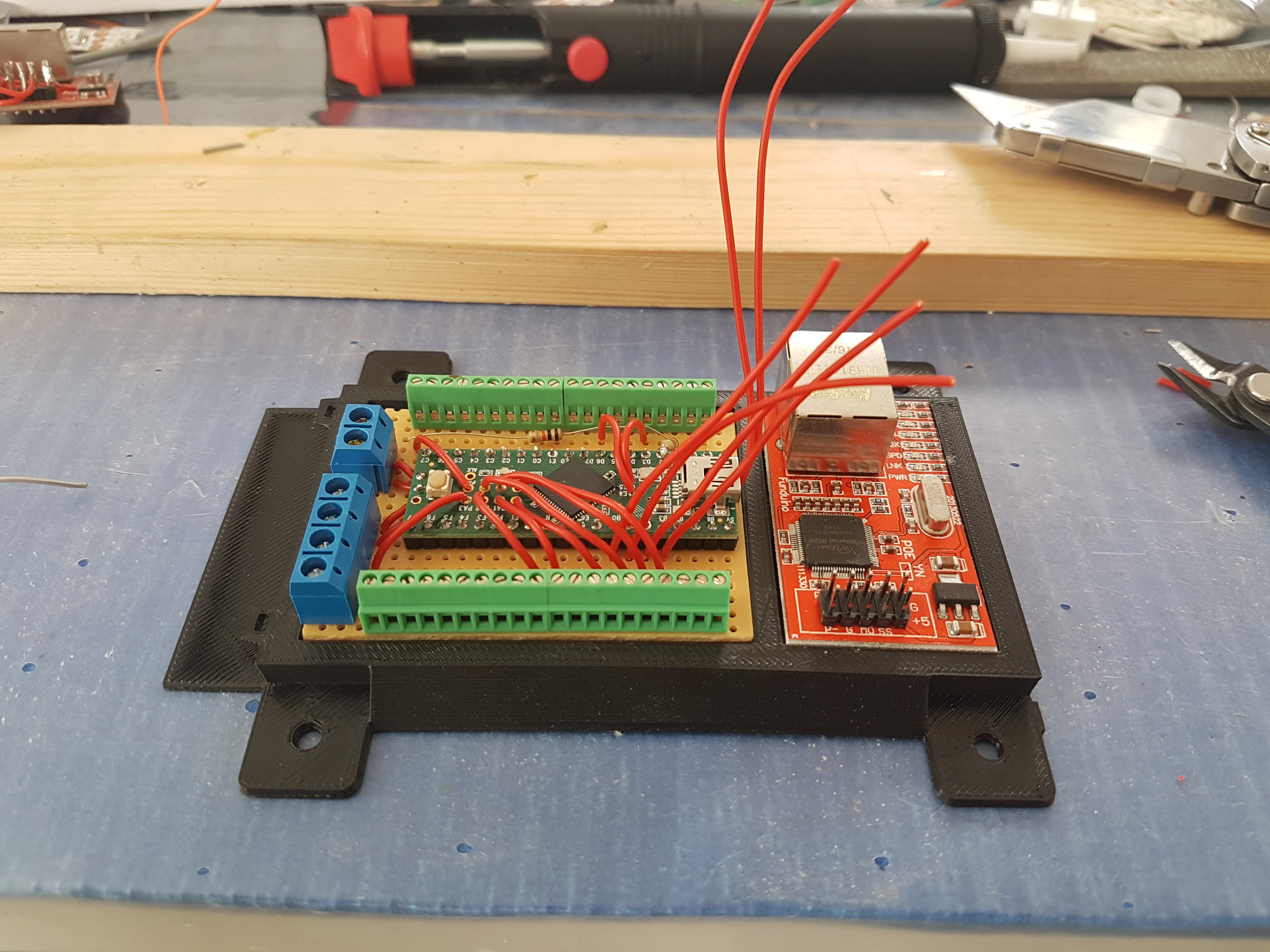
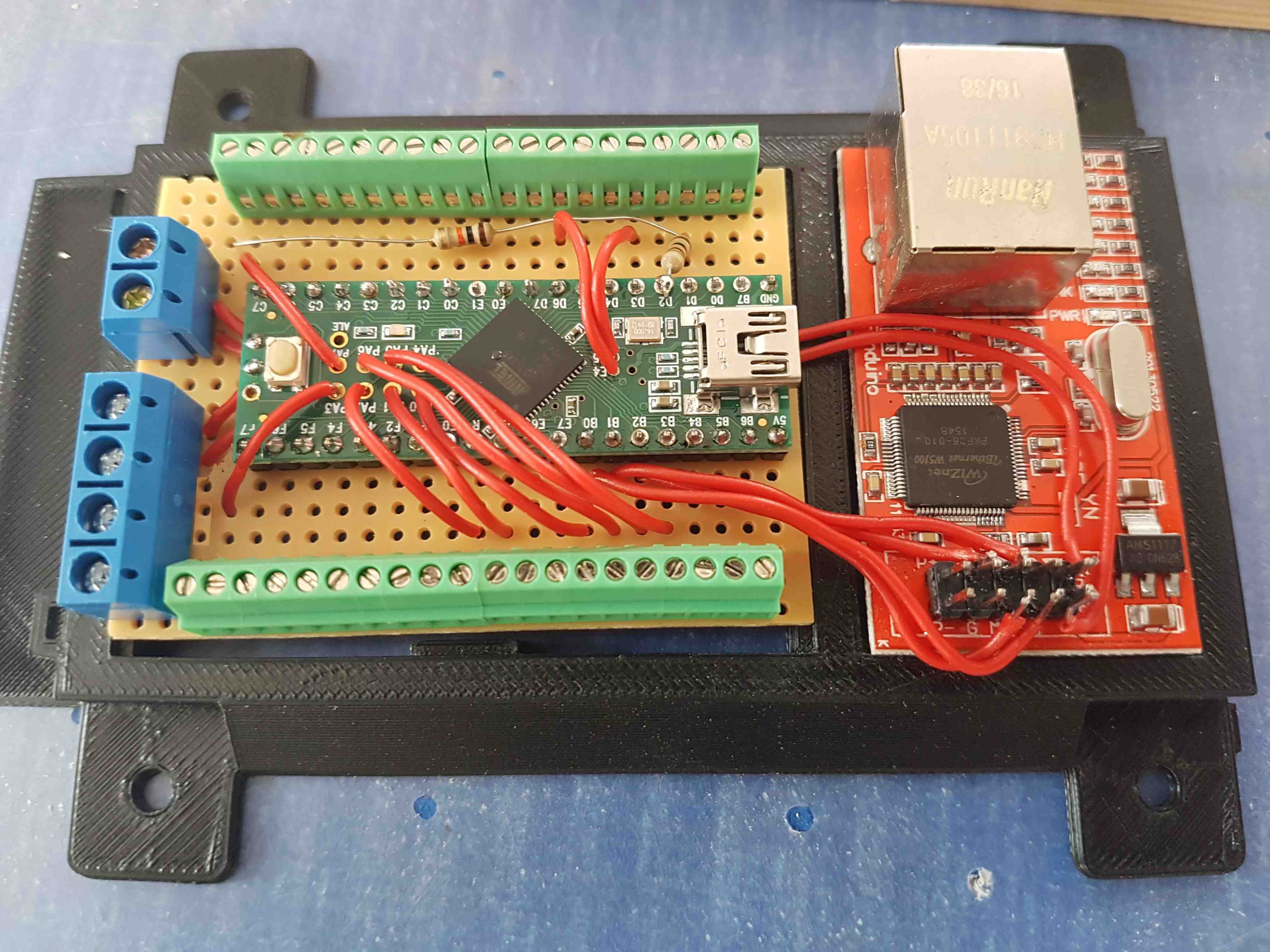
5Glue to the mount frame and solder to the ethernet board
![]()
![]()
40-way Ethernet Digital I/O extension for Loxone
Low cost 40 way digital I/O board, used to extend available IO to the loxone miniserver. Based on teensy 2.0 ++
Discussions
Become a Hackaday.io Member
Create an account to leave a comment. Already have an account? Log In.