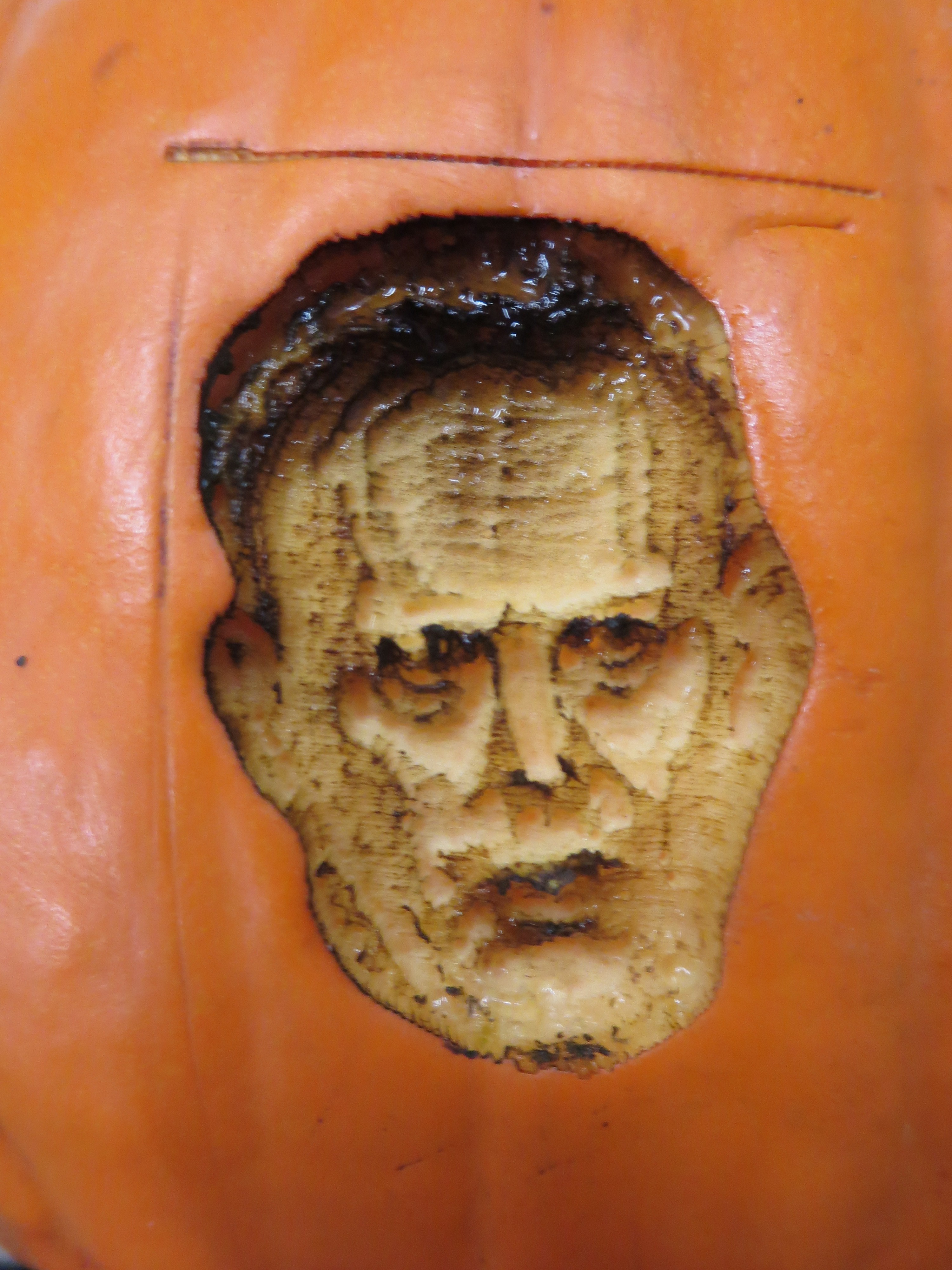
I'm making an electronic jack-o-lantern this year. I've laser-engraved Sean Spicer's face on a pumpkin and I'm going to put speakers inside it to play things Sean Spicer said. It also emits a pumpkin spice scent. It is: Pumpkin Spicer!
Halftone was the right technique! Engraving results:
That's illuminated with a pretty bright (17 W) LED bulb. I wiped some soot off the lower right of the face with a wet paper towel, which messed up the image a bit. Oh well.
I got the minimum viable product of Pumpkin Spicer ready for day 2 of Maker Faire. I just stuck a lightbulb on an extension cord inside and put the dish of wax melt next to it. Unfortunately, the incandescent lightbulb isn't really bright enough, but it melts the wax slowly:
For reference, this is the Sean Spicer photo I'm using.
On my test pumpkin I tried to engrave his face using several layers. In other words, the lighter the color in the photo of his face, the more times the laser would hit that pixel. Therefore, the pumpkin would be engraved deeper there, letting more light through. That was the idea, at least. It didn't work too well, and resulted in the Frankenstein-looking face you see in the photo:
Maybe it looks better illuminated? Not really:
I mean, you can see the contours, kinda, but it doesn't look like Sean Spicer.
So I next tried to trace his face both automatically and by hand, hoping to do vector cuts (faster to run, too), either partway or all the way through the wall of the pumpkin. However, well, see for yourself:
Not really usable. Unfortunately, this was the night before the first day of Maker Faire, and I ended up helping with some friends' projects, so I didn't have anything to show. Sometime in the last couple of days, possibly on my way to the Faire,* I had the idea of trying halftone.
*I'm super tired right now from trying to finish this project and from helping with other projects, so I can't remember when I thought of it.
I decided to try for the second day of Maker Faire, with the Pumpkin Spicer MVP (which consists of the engraved pumpkin and the pumpkin spice scent—I actually only thought of adding the soundbites a week or so after I first had the idea). Also, the Faire is being held in a horse barn, so the pumpkin spice would make Protospace's booth smell nicer.
Pixlr can do halftone reasonably well. I scaled up the image first (by 3 and a bit times), then applied the halftone filter with size 6, multiplier 10, no add, yes invert. Then I saved it and opened that in Paint to convert it to 1-bit BMP (which is what the laser cutter likes). The result:
I don't know where the outline came from, but I guess it's OK. Test engrave on a sheet of paper (too much energy density, but it shows that it works):
I'm not sure that looks like him, and it's a bit big for the pumpkin, so let's try again smaller and with a lower power setting:
I guess that looks enough like him. The banding seems to be moiré caused by scaling down the halftone image in the laser cutter software. Nothing I can do about it tonight. Now to prepare the pumpkin…
Last night I had some success testing the ESP8266 using some example sketches (Blink, WiFiScan, and HelloServer) and they all worked. Today I tried again and was able to get results from WiFiScan (which was still loaded on it). Note that those sketches don't involve connecting any external hardware to the ESP8266…
Then I tried to use the Button example sketch, hoping to use it to get input from my PIR sensor for testing. First, I tried to figure out which pin was pin 2 (the input pin in the sketch) by connecting a jumper wire from the 3.3 V supply pin to each GPIO pin in sequence. This was not a good idea. It caused the USB port to stop working. I got a message saying "The USB port 3 is not working" or something like that (which I didn't realize was a message from Windows) and the COM port stopped showing up in Devices & Printers as well as the Arduino IDE.
Then I tried to troubleshoot the USB cables (because every single post I found about an ESP8266 not working with USB turned out to be the USB cable's fault), with no success. Then I tried plugging the ESP8266 into different USB ports on my computer, which worked, but then I tried the same thing again and broke those USB ports too.
My wireless mouse's battery has failed, so I have to keep it plugged into USB for power. I unplugged it to try that USB port with the ESP8266, so I then plugged my mouse into my USB battery so I could continue to use it. However, it didn't present a large enough load for the battery to stay on, so I plugged my other USB battery (which was nearly empty) into the first USB battery to increase the load so the first one would stay on. That's how I'm using my mouse now.
I haven't been foolish enough to unplug my mouse's receiver and plug the ESP8266 into that port and try probing pins there. I guess I'll have to restart to get my USB ports working again.
But why did connecting the button input GPIO pin to 3.3 V cause the ESP8266 board to draw excessive power (which is what I'm guessing happened) when that's what the button that the sketch is designed for would do? Could it be because it's a sketch designed for Arduino boards?
Update: I restarted my computer and then promptly plugged in the ESP8266 board again without realizing that the jumper was still in place. At least I have two working ports now, not counting the one my mouse receiver is in.
awesome !!