 shlonkin
NOTE: This project is gradually improving. It is fully functional at this point, but it could be better.
It started as a pen plotter based on the entrails of a printer. It uses a pen to draw paths from a vector graphics file(SVG file). I wanted to make it do something that I couldn't do by hand, so I fed it a complicated image, a pcb layout. I then thought "Why can't I replace the pen with a small router and make something truly useful?" So I'm setting out to do just that.
There are numerous DIY pcb mills out there, but their router bits alone cost more than the planned budget of this project. It's not that I can't afford it, I just want to see if this is possible. I'm open to ideas and criticism, so let me know what you think.
0%
0%
PCB mill for under $10
pcb mill built from garbage using basic hand tools and little money
Become a Hackaday.io member
Already have an account? Log in.
Just one more thing
To make the experience fit your profile, pick a username and tell us what interests you.
Pick an awesome username

hackaday.io/
Your profile's URL: hackaday.io/username. Max 25 alphanumeric characters.
Pick a few interests
Projects that share your interests
People that share your interests
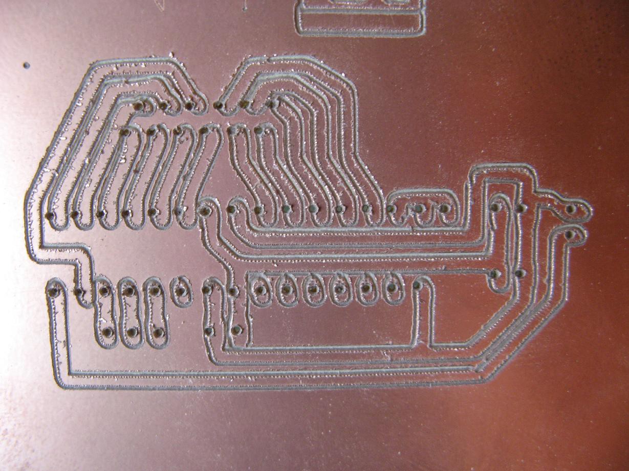
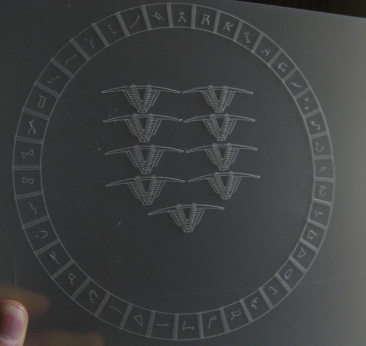
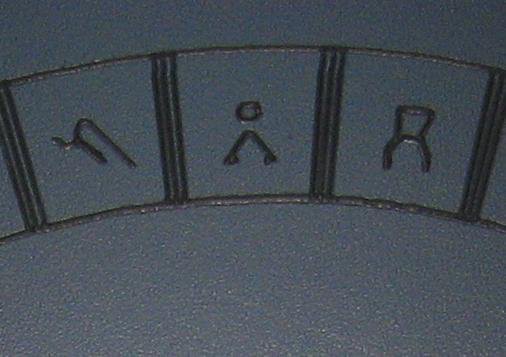
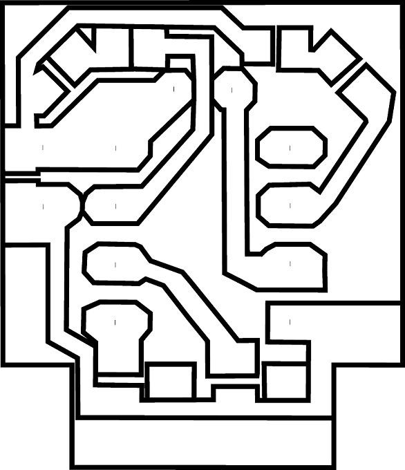
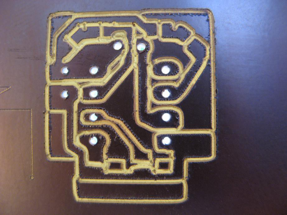
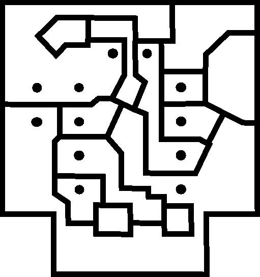 And here is the result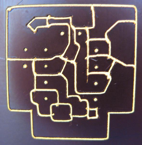
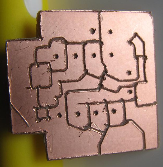
 Not perfect, of course, but considering the quality and cost of the tool I am completely satisfied with this result. This precision should be plenty for the through-hole and larger smd circuits I build. I am overjoyed that I finally have a chemical free way to make pcbs at home.
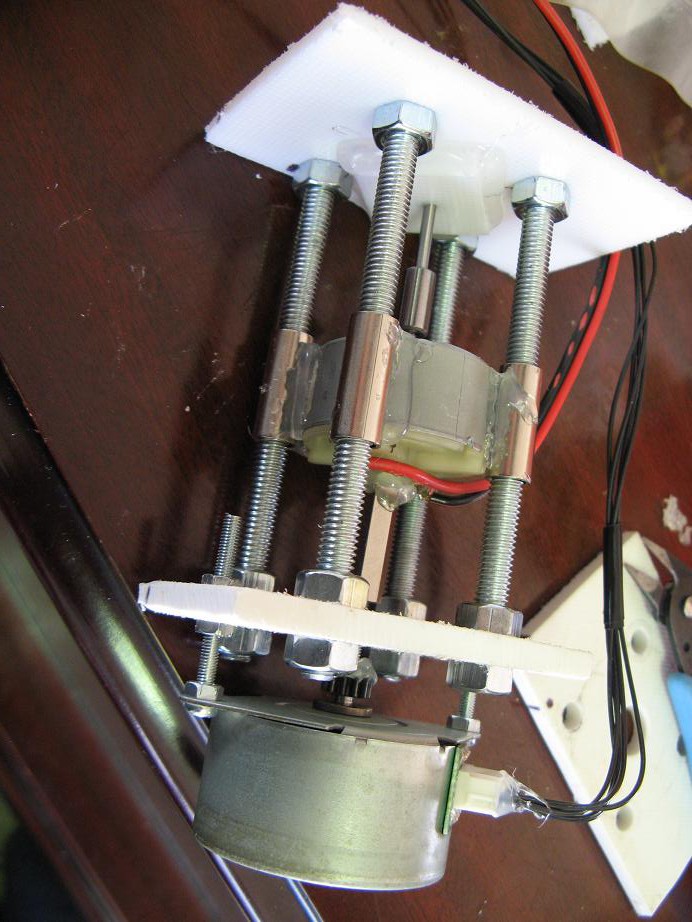
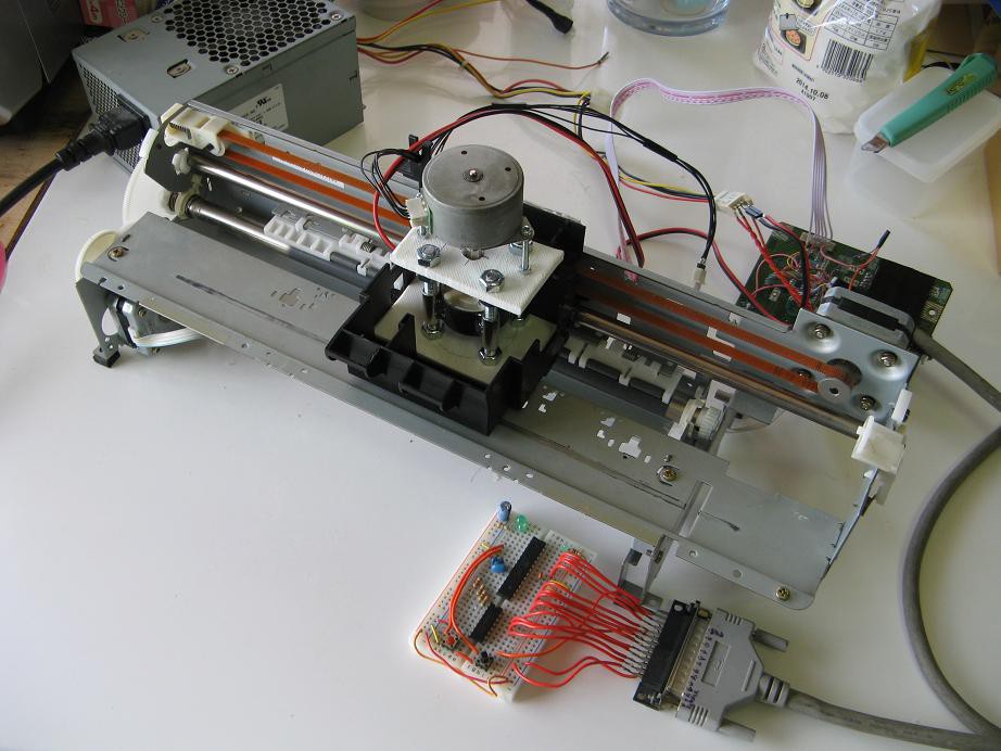
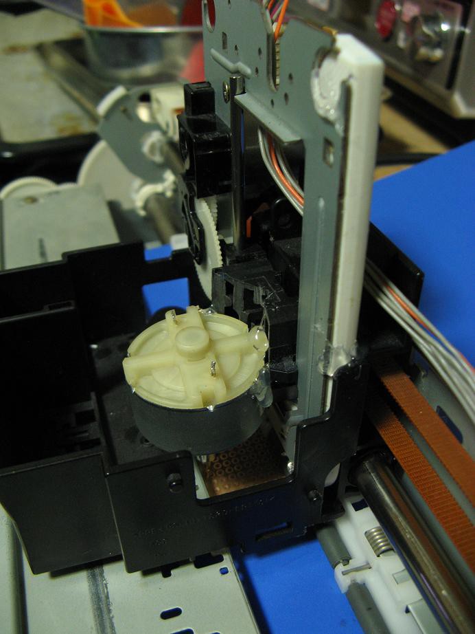
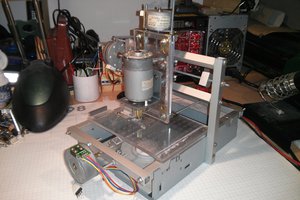
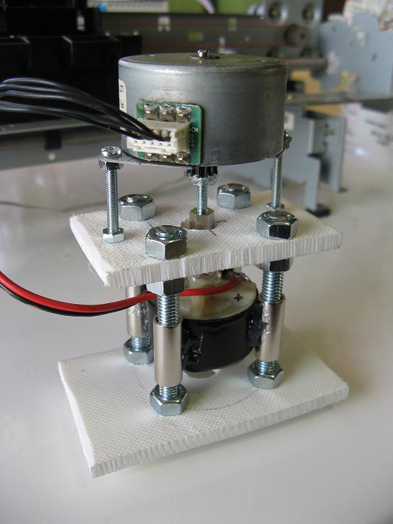 I think the picture is pretty self explanatory, but I'll try to describe it. Note that everything is temporarily tacked together with hot glue. The idea is that the final device will be held together with a much more permanent and strong adhesive, but you know, sometimes I get lazy and the hot glue stays if it works. The top motor is a 7.5degree/step, 4-winding, unipolar stepper that I probably got from a fax machine. It is coupled via a 3mm screw and long nut to the cutting motor. Both of these run on 12V.
 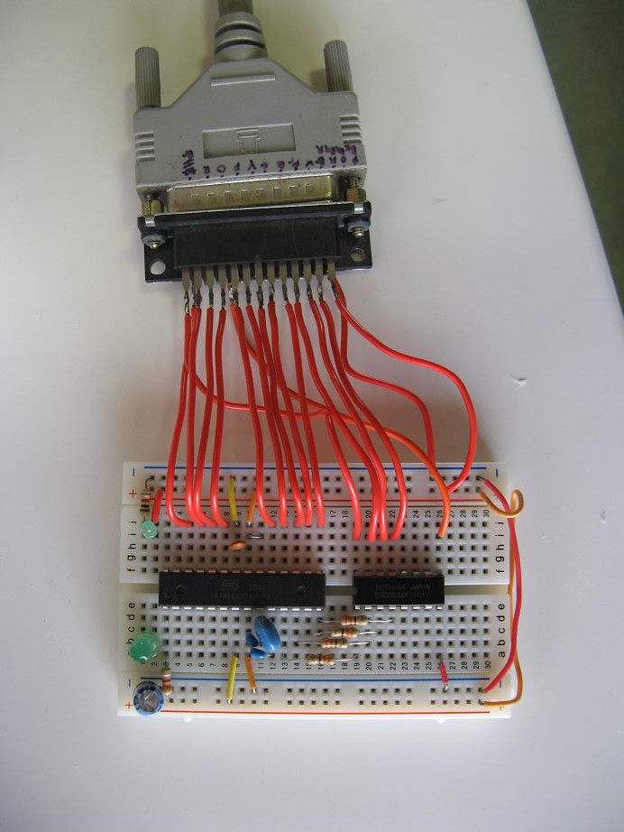 Notice that I have now switched to a stand alone microcontroller, but it still makes use of Arduino. The smaller chip is the darlington array.
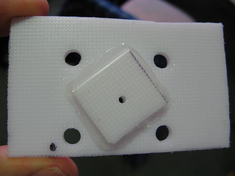
 And finally, the part you've all been waiting for. I just had to give it a test drive to see what happens, so I stuck some dense cardboard in it and cut a little 1cm square thing. Everything worked smoothly and the result looks great. Now if i can get a similar result on an actual pcb I will be filled with joy.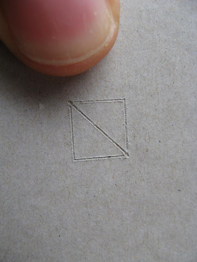
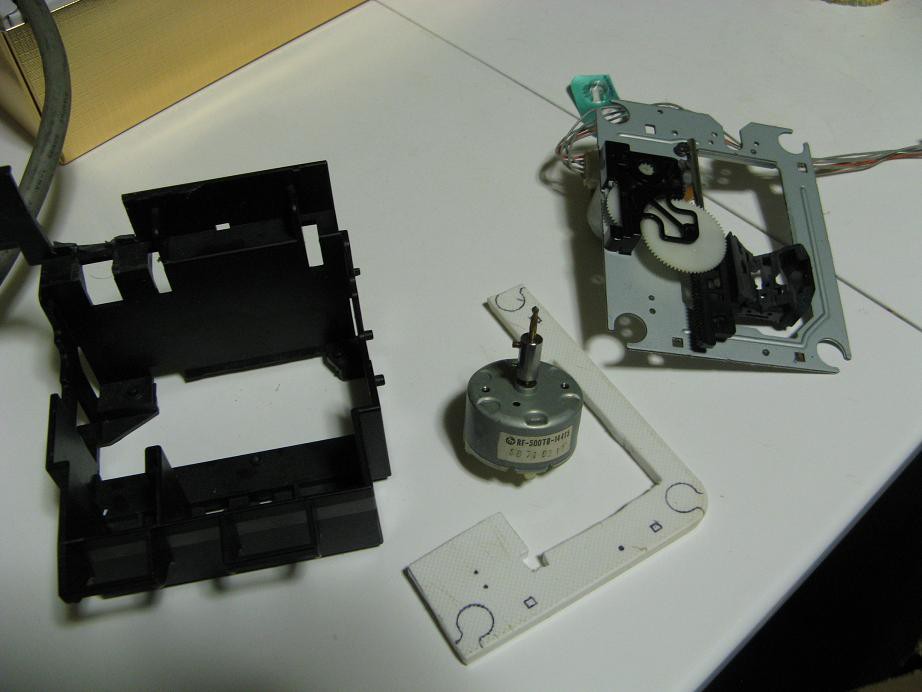
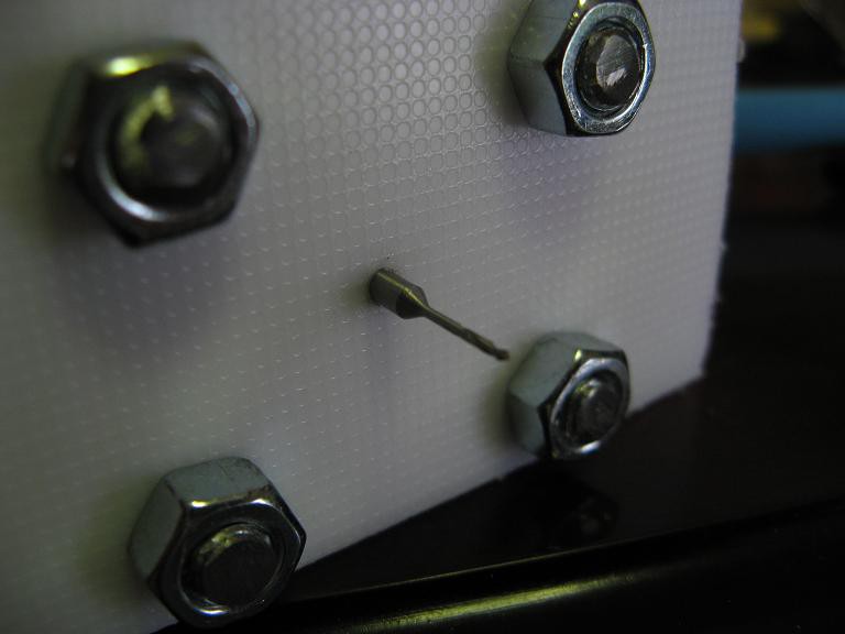
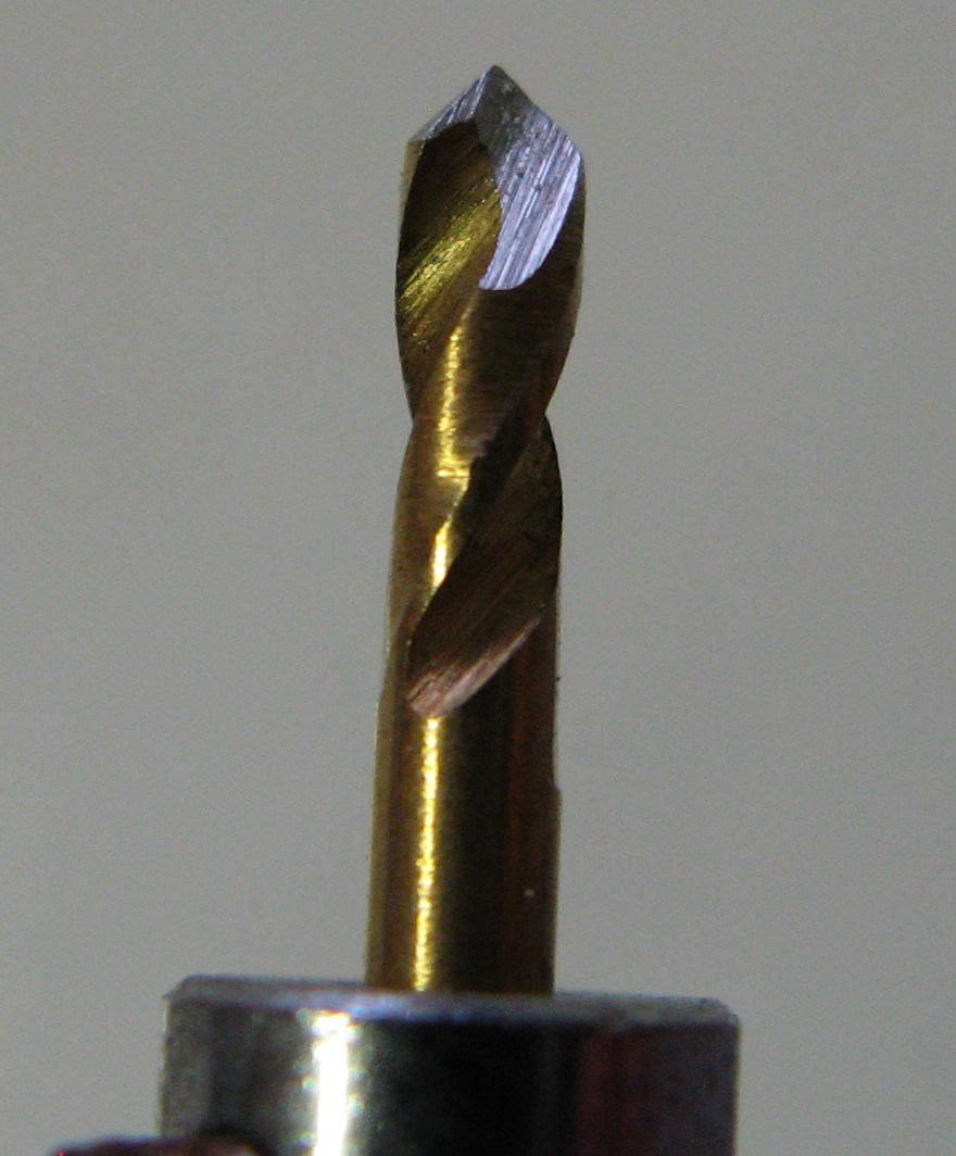 The finished bit
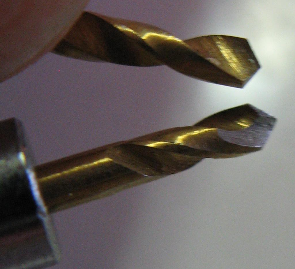 Compared to the original bit end.
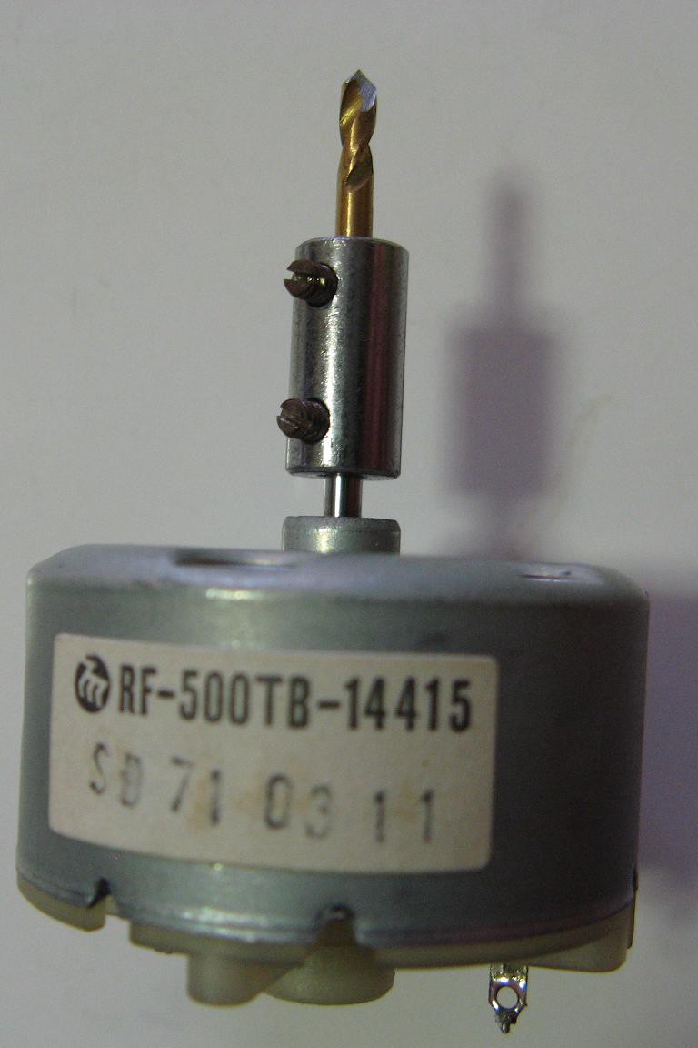 Attached to the motor.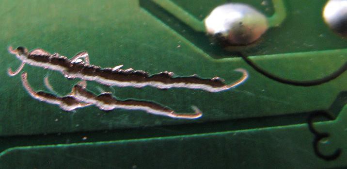













 Stefan Lochbrunner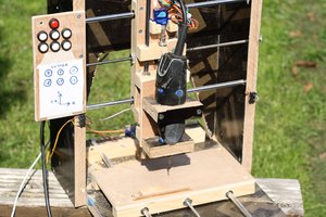
 penleeki
 charliex
 zakqwy
Ok so a few questions. You are limiting this to a PCB board? Just to save time etching? Making sure, if you wanted to do a full mill, customizing a 3d printer, I have alot of tips I could send your way.
Otherwise I cant see from the pictures.... how are you controlling the Z axis?
Ok nevermind saw the post below.... alright... well i guess do you have video of it working? Still not quite understanding how the Zaxis is working in this.
Anyways sometihng to look at offhand (just saw your comment about target budget)... You could try using the parts to make the z axis on the plate plane. Yes it would limit drilling area depending on the plane possibly, however It woul allow you to fix the motor directly to something solid... More stability in cutting from the motor itself instead of having it move. It might slow down cut time and youd have to configure a Zaxis bed, but... its an idea especially since you are just making shallow cuts here for pcb board.