-
Some problems and limitations
05/06/2014 at 05:48 • 7 commentsAlthough this mill has produced some good results, it has also made some garbage. It would be naive of me to expect this mix of dumpster parts to perform as well or reliably as a proper mill. I don't want to make this sound too discouraging, but I'll try to describe some of the weak points of this project.
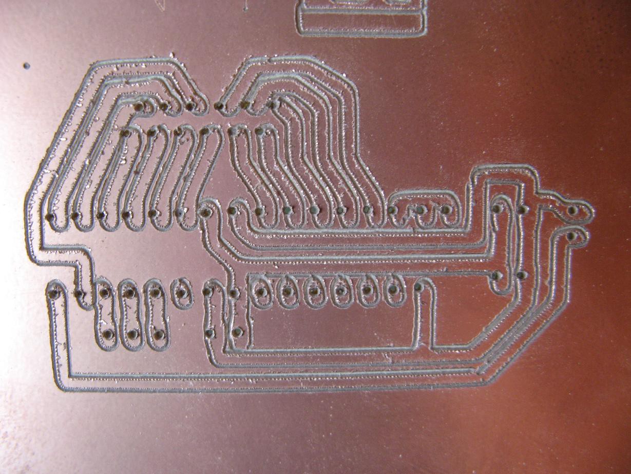
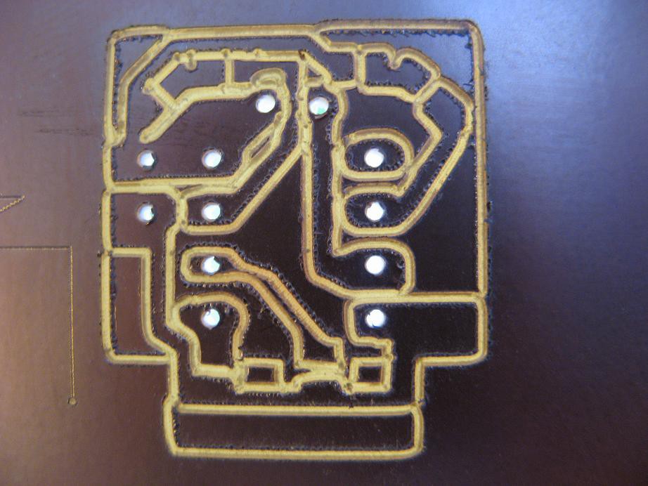
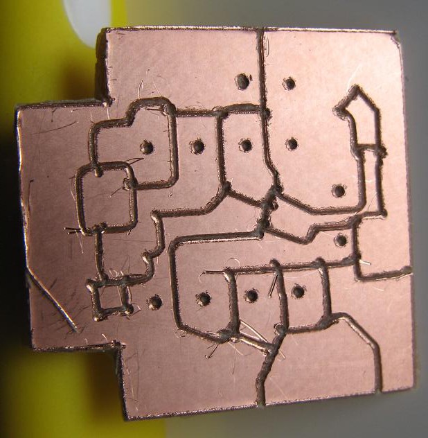
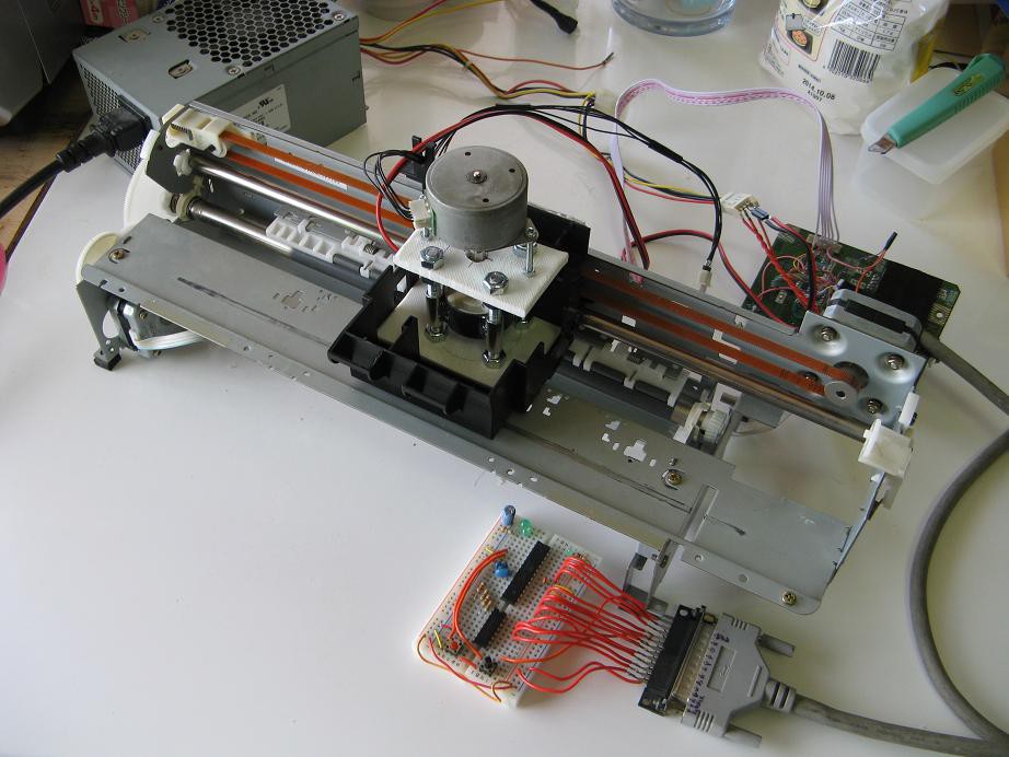
The X and Y axes behave exactly as they did in the printer. One motor moves the print head along a shaft using a toothed belt, while the other turns a roller that moves the object via friction. I have not had any real problems with the print head axis, but the paper axis is not as reliable. There were no problems when I was simply drawing on nice, flat paper. When milling, however, I produce lots of chips, dust and bumps in the surface. Usually these are able to go through the rollers just fine, but sometimes something gets caught and the board slips slightly. Unfortunately, even a slight shift can completely mess up the result. Here is a picture of a pcb for which there was a little slip that caused the drilled holes to be off. As a result, this pcb is no longer functional.
I also had a problem with friction wearing out the plastic "bearing" that guides the bit. It is not actually a bearing, but simply a tight hole in the plastic base of the Z-axis. While milling parts for the stargate project, the mill had to work for rather long periods of time. After a while I noticed that the bit had enlarged the hole in the plastic. It probably melted slightly from friction. I started applying a little oil each time I use it, but the enlarged hole has thrown the precision way off. Of course this could be fixed by replacing the plastic part and remembering to oil it.
A third problem is with cut depth. At this point I have to calibrate the cut depth each time by eye. I've looked at zeroing methods used on other designs, but they would not work here due to slop in the Z-axis. I'm usually able to eyeball a reasonable depth, but sometimes it is just a little too shallow, causing poor electrical isolation, or too deep, causing too much loading on the bit that results in poor precision.
This project has been very educational and a ton of fun. I'm pleased with the way it has turned out, considering the cost and parts used. But with these problems, pcb production has been a long and wasteful process. I'm looking for an alternative and these are some of the options I'm looking at:
- A properly designed and funded mill.
- Chemical etching, which I am trying to avoid.
- Buying them from a fab house. This gives the best result, but lacks fun, education and the feeling of hacking.
- An entirely new experimental method. This is by far the most difficult and educational way. If I can do it, maybe I'll enter it in the hackaday contest.
Do you have any other ideas?
-
A new use and big software updates
04/01/2014 at 14:35 • 0 commentsIt is always satisfying to find more uses for projects. I guess that's because so many of them just end up on a shelf collecting dust, not that that will likely happen to this tool.
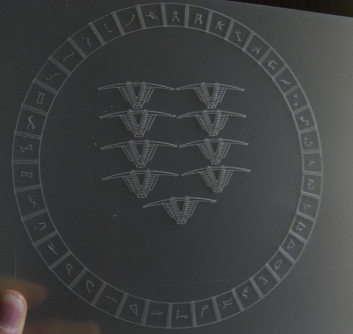
I am working on a stargate for the sci-fi contest (shameless plug for our entry) and was faced with the task of carving lots of tiny details into thin, flat plastic. What an ideal task for this mill. I drew up some svg images of the stargate details and tried milling them into some 1.2mm polypropylene sheet. Here are some of the results.
It was a great success. It also led to several significant software changes listed below.
- Cut depth is adjustable on the fly via the processing sketch.
- All important parameters on the controller can be set via processing.
- The math was rewritten to solve some accuracy bugs and be more efficient.
The updated code is in the usual places:
- SVGMill.ino (arduino code)
- SVGReader2.pde (processing code)
-
Accuracy improvement and drilling capability
03/28/2014 at 00:19 • 2 commentsI was not very impressed with the sloppyness, so I decided to redesign the Z-axis to reduce lateral play in the bit. I also thought it would be great if I could drill holes at the same time. I spent another $2 and got some new threded rod and a 0.8mm bit designed for a hand held router(dremel type thing).
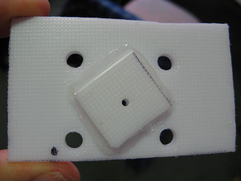
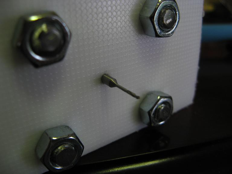
The bit now travels through a snug, but not tight, hole in two layers of 5mm HDPE. Yes, that would be the cutting board again. This takes the side loading off of the motor and holds the bit much more steadily.The new bit is much longer and needs more travel for drilling, so I lengthened the z-axis with some new threaded rod. Other than the new bit, new plate with hole for the bit, and new threaded rod, the hardware is pretty much the same.
The software needed some upgrades to handle drilling. Since there is no single point object in the SVG language, I just made tiny line segments with length below some threshold value. The code interprets these tiny segments as drilling locations and sends a drill command to the arduino. The updated code is here:SVGMill.ino - the arduino code
SVGReader2.pde - the processing code
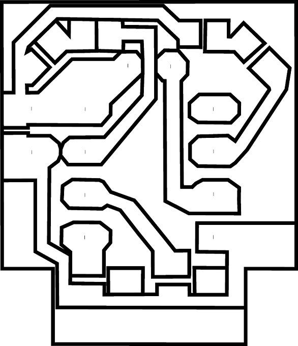
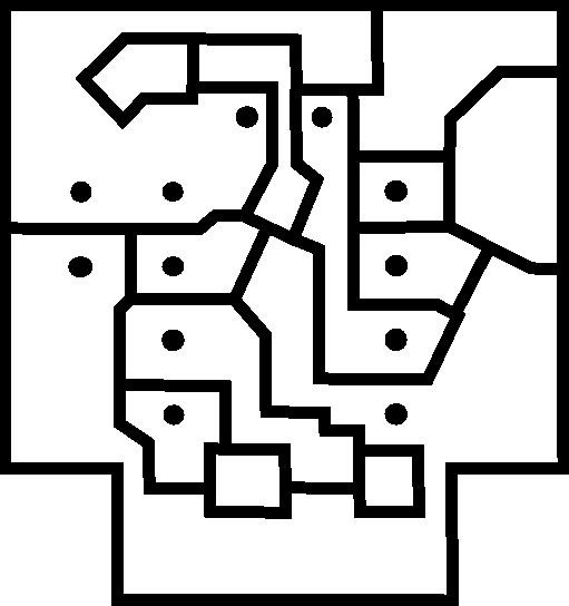
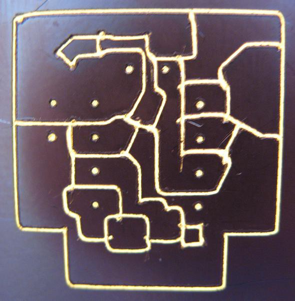
And here is the result. I made the pcb a bit more traditional in style this time. The result is still far from perfect, and there is one trace that is just barely surviving and probably needs a good solder coat, but it is far more precise than the last version. Oh, and it has holes automatically drilled. That's a huge improvement. First is the ideal image, then the actual result.
-
First pcb, code uploaded
03/17/2014 at 04:50 • 1 commentThe first real pcb made with the mill is for a tiny robot. It includes such milling challenges as 0603 smd resistors and SOT-23 transistors, as well as a narrow trace running between two 2.45mm pitch holes with pads.
As intended, this shows the limits of precision with this tool. It is certainly far from perfect, and there are some almost fatal bits of sloppyness, but the board is perfectly functional. All of the scratches and cuts came from trying to cut the board out from a larger piece and from running a small screwdriver along the cuts to clear debris. I quickly tested for continuity between all neighboring parts, but everything is properly isolated.
First, here is the intended pattern which was made in Inkscape after laying things out in Eagle.
Also, I have uploaded the Arduino code here. It is very similar to the code for the plotter, but altered to work with the new z-axis and such.
From here I would like to find a way to improve precision, but I doubt it will get a lot better. That's OK. This is functional and thus much better than nothing. On the other hand, I might do as well by drawing the pattern in ink and then cutting it by hand with a dremel. But where's the fun in that.
Side note: This is a good x,y platform for thin, flat objects that don't impose large side loads. I'm thinking cnc glass engraving, laser etching, ... any other ideas?
-
Successful copper cuts
03/14/2014 at 00:03 • 0 commentsHere it is:
 Not perfect, of course, but considering the quality and cost of the tool I am completely satisfied with this result. This precision should be plenty for the through-hole and larger smd circuits I build. I am overjoyed that I finally have a chemical free way to make pcbs at home.
Thanks to the people who gave me feedback and followed this project. It's not over yet, though. I still need to finalize schematics and clean the code before I post them here, but that will come in the next few days I hope. Also, I need to produce an actual pcb. I'm thinking a small celebratory robot.
-
New z-axis, first test cut
03/11/2014 at 06:40 • 3 commentsBefore you get too excited, that first cut was just in dense cardboard, not the real thing. But we'll get to that shortly.
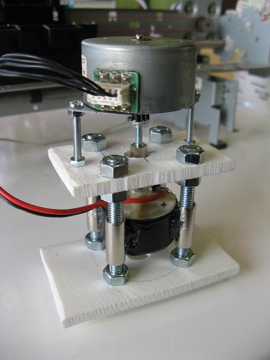
As I mentioned before, I really needed a new z-axis design, so I went to the place where I can really concentrate and piece things together in my mind, the hardware store. I eventually decided on the following:
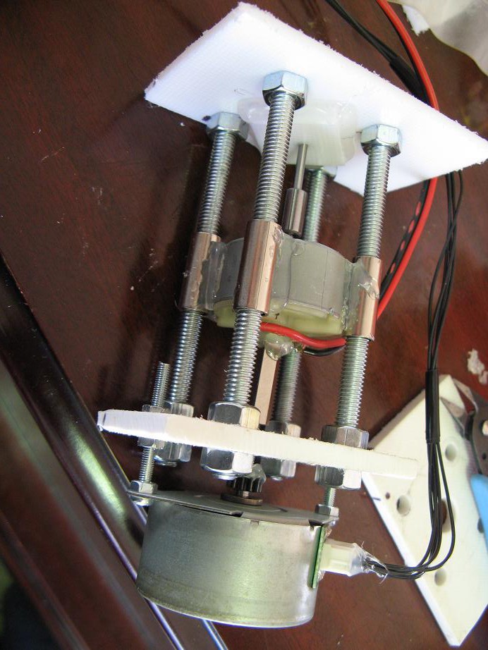
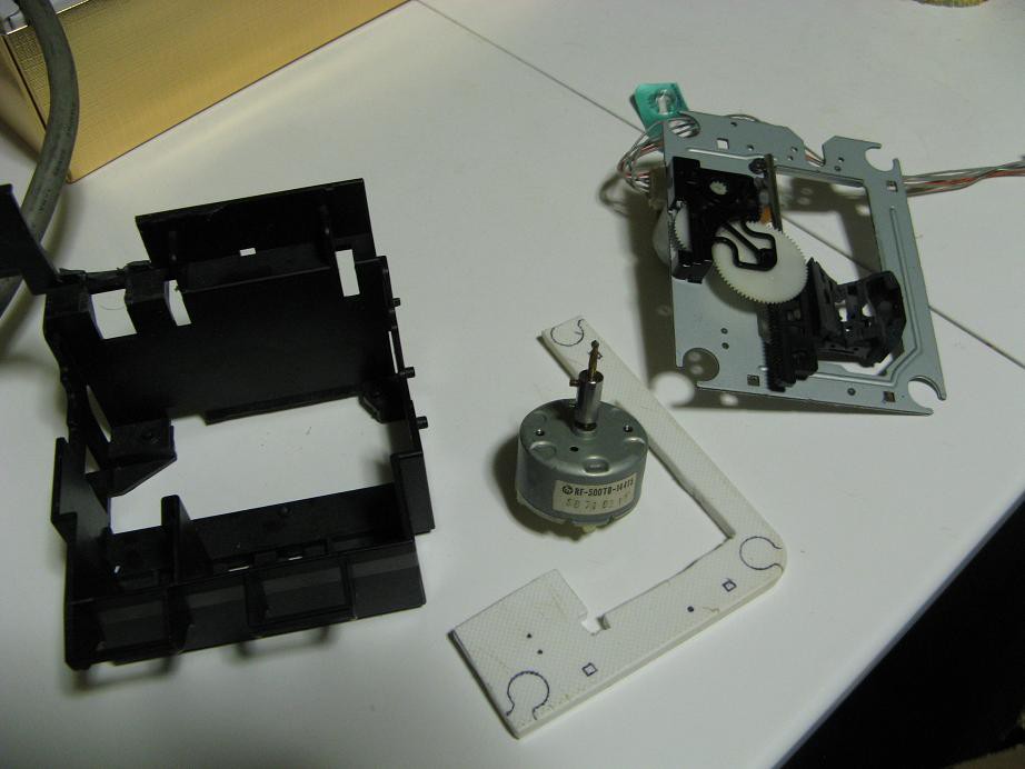
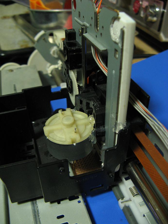
 I think the picture is pretty self explanatory, but I'll try to describe it. Note that everything is temporarily tacked together with hot glue. The idea is that the final device will be held together with a much more permanent and strong adhesive, but you know, sometimes I get lazy and the hot glue stays if it works. The top motor is a 7.5degree/step, 4-winding, unipolar stepper that I probably got from a fax machine. It is coupled via a 3mm screw and long nut to the cutting motor. Both of these run on 12V.
 The bottom motor is snugly fixed between four bushings that ride up and down 6mm bolts. I was really careful with positioning, so there is almost no lateral play in the motor, and the bushings slide with ease.
The white structure is made from a cutting board pulled out of the garbage. I love working with that stuff. If you ever find such a chunk of plastic, don't pass it up.
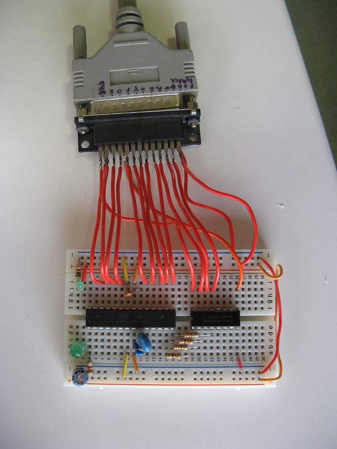
The stepper is driven with a convenient darlington array with built in clamping diodes. I don't remember what I pulled that out of, but it was a lucky find. Here is the updated controller (I'll post schematics once they are finalized):
 Notice that I have now switched to a stand alone microcontroller, but it still makes use of Arduino. The smaller chip is the darlington array.
What is the cost of this new z-axis? The only things I had to buy were some of the screws, nuts and bushings. It came to 200 yen (about $2).
And here it is in place:
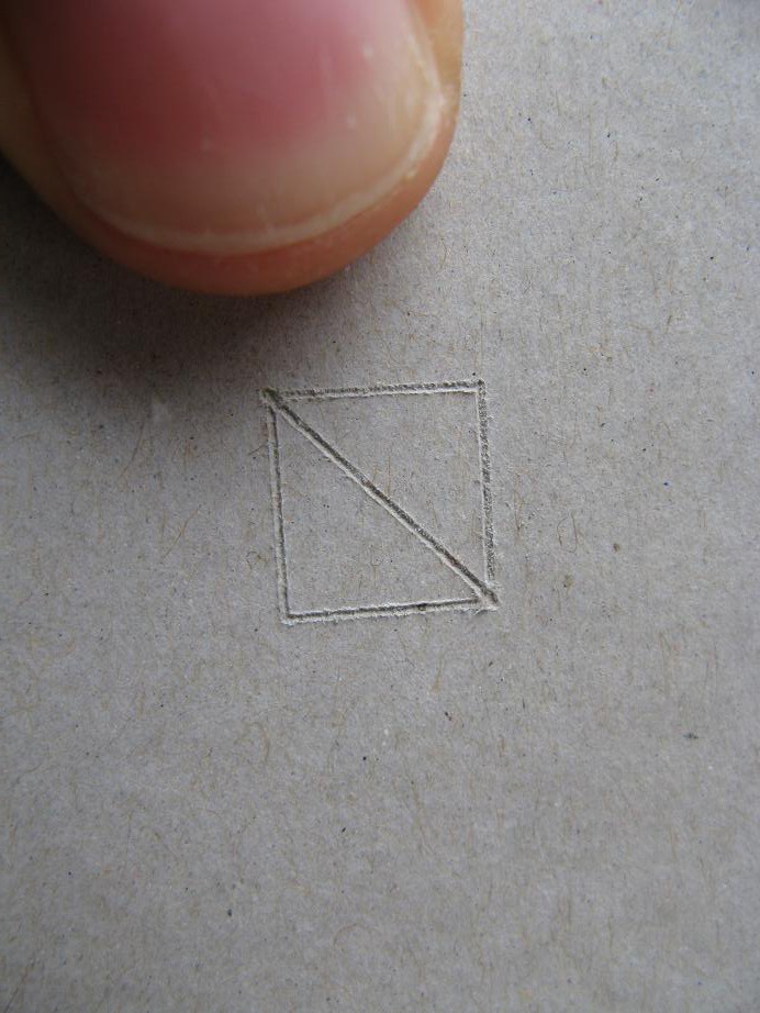
 And finally, the part you've all been waiting for. I just had to give it a test drive to see what happens, so I stuck some dense cardboard in it and cut a little 1cm square thing. Everything worked smoothly and the result looks great. Now if i can get a similar result on an actual pcb I will be filled with joy.
 -
test fitting and redirection
03/08/2014 at 06:16 • 0 commentsBefore you glance at the pictures and laugh at my poor engineering skills, read the log.
I trimmed several bits of plastic off the print head carriage , made an adapter out of a piece of plastic cutting board from the garbage, and tacked everything together with a little hot glue to test the fit. It all went together well, and you can see that the rollers nicely accept a 1.6mm protoboard, even with the blue plastic backing sheet.
But then I took a look at what I had built and started pushing things around. I started having doubts. There is a little too much slop and I don't know how well the z-axis motor and gear set will perform. It works perfectly for moving a pen across some paper, but there will be significant forces on the bit.
It's time to rethink this part. I am currently pondering some other designs. A bolt attached to a stepper and a long nut attached to the cutting motor would give me the strength and z-axis precision I need. How about a piece of PVC slightly sanded and lubed sliding inside a PVC coupler, with the motor glued in the moving piece and the other held rigid. That would take care of lateral forces. I can think of a lot of other setups that may work better, but I'm sticking to minimal money and no fancy tools.
As always, tell me what you think of these ideas and share your own ideas.
-
Bit modification and tests
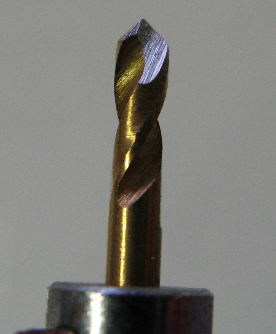
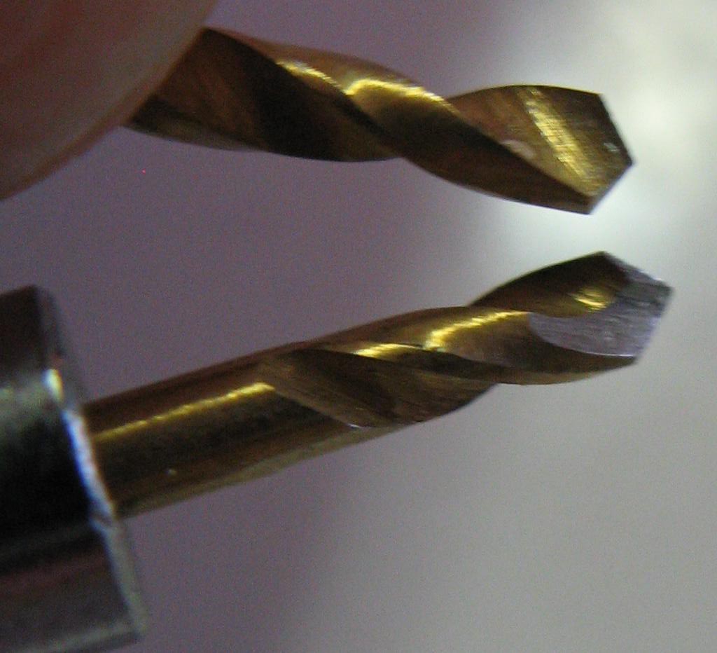
03/05/2014 at 01:12 • 0 commentsI started with a 2mm cheap drill bit and turned it into something a little more appropriate. The only tool I used for this was an angle grinder with a cutoff wheel. I intended to use a small file to finish it, but the angle grinder did such a nice job, I didn't bother.
First I shortened it to about 15mm in length. Then I carefully spun the bit between my fingers while holding it against the wheel at an angle. If you try this, be sure to wear gloves since your fingers are so close to the spinning death wheel(I don't have to mention eye protection, right? That one's obvious I hope). Anyway, that gave me the taper and the result looked similar to the original bit end. I was planning on a steeper taper, but I stopped at this point. Then I stuck the bit in a vice and very carefully gave it a gentle touch with the grinder to shape the flutes(Is that what they're called?) into something that would be better for this purpose. I think. I'm not an expert. here are some pictures:
 Compared to the original bit end.
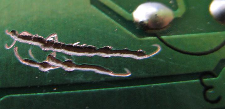
Of course all of this work would be for nothing if it doesn't do the job. To test it I found a junk pcb with a wide area of copper. Holding the spinning motor carefully in my hands, I tried to cut a small line. The result looks sloppy because I was just holding the motor in my shaky hands while trying to maintain a consistent depth. It works! It cuts right through the copper and into the substrate without noticeable strain on the motor.
-
Initial offering - functional pen plotter
03/04/2014 at 02:00 • 3 commentsThis plotter was actually a project from years ago and the details are documented on my blog here:
http://junkplusarduino.blogspot.jp/p/svg-image-plotter.html
It's capable of fairly precise drawing. Certainly precise enough for a simple pcb. The z-axis, on the other hand, is just a dc motor that I pulse on for a few hundred ms. I may need more precise control for milling, so I might swap it for a similar dvd player part that uses a stepper motor. But I've been wondering, since I'm only working with one type of material with consistent thickness, and I'm only trying to mill off a very thin layer of copper, I really only need two z-axis positions: up and down. The up position doesn't even need to be precise at all. I could, perhaps, just set a tightly adjustable stop for the down position and run the tool down until it hits the stop. What do you think?
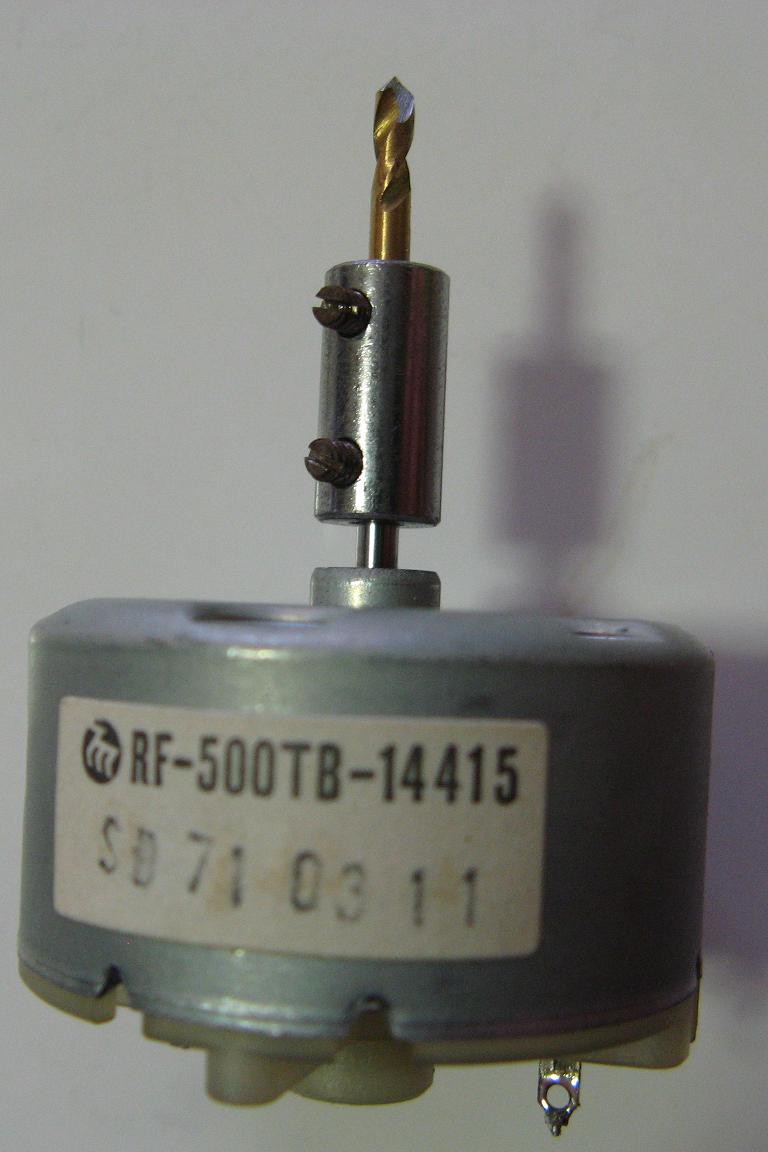
The next thought is the spindle and bit. I have a whole box full of DC motors from various junk. I picked out a 12V one that spins quickly with decent torque. I even had a little coupler, a sleeve with two set screws, that snugly fits the shaft and a 2mm drill bit. I tried it out by drilling some plastic. It works as long as I don't put a ton of pressure on it. Of course a drill bit is far too long and not designed for this sort of thing. I have an angle grinder and files. Could I chop the bit down to a short piece and carefully shape the end into about a 60 degree taper? I know the metal quality will be a significant factor, but it doesn't hurt to experiment with dollar store drill bits.
Oh, I had another idea. Rather than a milling bit, how about an abrasive "diamond" bit with a tiny ball end. I've seen those in the dollar store too. If I mounted it at an angle, it could grind away the copper. Hmm... It doesn't sound too precise, but it's an idea.
PCB mill for under $10
pcb mill built from garbage using basic hand tools and little money
 shlonkin