Close
0%
0%

Variable speed washer motor and controller reuse

Motors and controllers can be salvaged from scrapped washing machines. This project delves into reusing the motor controller too.

Similar projects worth following
Document how to use a high frequency variable speed motor and the motor controller from a Maytag washer. By salvaging the motor and motor controller you have a complete variable speed motor (with feedback) that can be driven with a simple PWM torque signal.

Description

I salvaged the motor and motor controller from a scrapped Maytag MAH7500 Neptune front loading washing machine. These are relatively easy to find. I have seen other projects online that reuse the motor with an external VFD but have not seen an explanation of reusing the motor controller. This project is intended to illustrate how I figured out how to use the motor controller and motor.

The service schematics comes with the machine and is also available online. You should look up the exact details for the washer you find but these are mass produced units and I expect all Maytag Neptune or similar models will use nearly identical systems. 

You can easily check the motor and controller by pulling the JP4 six pin connector to the motor controller. This enables a diagnostic mode and If the motor and controller are good the system will spin slowly. (50 RPM?) If it spins, salvage the motor, motor controller, and the wire harness connectors attached to motor controller. I recommend grabbing the belt and the pulley attached to the tub. I think I tossed my pulley which I regret as this is a high speed motor and you will probably want to use the mechanical reduction.

System 

The motor is a high frequency induction motor and the motor controller converts AC line to DC to three phase motor power. Line voltage goes to MN4. 

The service schematic only shows three other signals going to the motor controller. MTR CTRL TACH, TORQUE PWM, and WTR CONTROL SIGNAL COMMON. Looking at the motor controller board I saw some CNY17 opto isolators near JP4 which leads me to believe the signals are opto isolated.

Control Signal Description

MTR CTRL TACH

The schematic shows a tachometer signal coming from the motor and into the motor controller. This signal appears to be available and opto-coupled at the JP4 connector pin 5 red wire labeled MTR CTRL TACH. I used a pull up resistor to 5V and observed this signal on a scope. I spun the motor by hand two quick revolutions and saw eight pulses come out. So this is a 4 pulse per revolution tach signal. I expect this signal could go straight into a micro controller with an internal pull up. When the motor is being driven I do see some noise on this line. If this persists when I clean up the wiring, I will filter this signal.

TORQUE PWM

This is the only control signal input. My first attempt was driving this with a 0-5V square wave and varying the frequency. Nothing happened until I exceeded 70hz at which point the motor spun up fast. Like 375 hz or 22500 RPM fast. At that point, I realized the control signal is proportional to duty cycle and not frequency. With no load on the motor it will spin at max frequency with a 50% duty cycle. My function generator will only go to 20% duty in the square wave mode. Using the pulse mode, I found the motor will start up when the frequency is >70 hz and you bump the duty >4%. With no load on the motor, it only requires approx 3% to keep the motor spinning at a couple hundred RPM. At  4% the motor will ramp up to full speed. 

WTR CONTROL SIGNAL COMMON

This appears to be the ground signal for the MTR CTRL TACH and TORQUE PWM signals. These signals may be opto coupled inside the motor controller. This signal is NOT POWER COMMON.

Mechanical 

Many applications for small electric motors use four pole motors (1750 RPM). The motor shaft has a 7/8" pulley and I think the (lost) pulley for the washer provided a 11:1 speed reduction which dropped the motor from 375 hz or 22500 RPM to about 2000 RPM. So if this is used to replace a standard motor you should probably keep the mechanical reduction.

Next Step

Now that I understand the TORQUE PWM signal and the MTR CTRL TACH feedback, I will use a micro controller with PID to control the variable speed system.  This system will probably end up driving a drill press, belt sander, or small lathe.  Correctly sized for the application, I should be able to achieve precise speed...

Read more »
PWMNoise.PNG

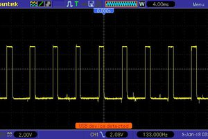
Scope shot with yellow TORQUE_PWM and green MTR_CTRL_TACH. The MTR_CTRL_TACH is too noisy (16khz) to read until 140-150msec after I turn off the TORQUE_PWM.

Portable Network Graphics (PNG) - 52.70 kB - 01/08/2018 at 06:25

Preview

  • Successful Reverse

    Jerry Trantow01/08/2018 at 06:24 0 comments

    Steve scoped his washer and figured out the state of the TORQUE_PWM signal determines the rotation direction. I put together a quick Arduino test and verified this works for me. Thanks Steve!

    I added an interrupt to the Arduino code but the MTR_CTRL_TACH signal is too noisy until 140-150 msec after I turn off the TORQUE_PWM. I was using the internal pullups on the input pin. I see real sharp 16khz noise spikes on the tach signal so I will have to figure out some filtering or how this noise gets on the line. I added a file with the scope shot of the noise. Yellow is TORQUE_PWM signal, Green is the MTR_CTRL_TACH signal.

  • Reverse

    Jerry Trantow12/23/2017 at 05:41 0 comments

    I have been unsuccessful at reversing the rotation of the motor. All we have to play with is the frequency and duty %. I was hoping a different frequency or duty > 50% would reverse the motor but no luck so far.

    If anyone has a working washer I am interested in whether the tub ever reverses direction??? If yes, it would be great to see a scope on the TORQUE PWM signal in reverse. It would also be nice to verify the frequency during normal operation.

    If the motor controller isn't designed to reverse, it would be easy to add a DPDT switch/relay/contactor to swap two of the winding wires between the controller and motor to change direction.  (2Amp 250V AC)

View all 2 project logs

  • 1
    Arduino Code

    I put some test code at https://github.com/JTrantow/MaytagMotor.git This should be enough to run a motor at a desired RPM (with feedback). Plan to connect an encoder and LCD.

  • 2
    LinuxCNC/MachineKit Integration

    Once I test out some ideas on the Arduino, I intend to integrate PID control and RPM display in LinuxCNC/MachineKit configuration for my lathe.

View all instructions

Enjoy this project?

Share

Discussions

Steve wrote 02/05/2018 at 00:05 point

I got a pulley for a 5/8" shaft but it doesn't fit and I found the motor shafts to be metric.  The older motor has a 17mm shaft and the newer one has 15mm.  To get the pulley to fit the 17mm shaft I had to bore it out slightly.

  Are you sure? yes | no

Steve wrote 02/03/2018 at 19:29 point

BTW, none of this will work with newer models like the MAH9700 that has a pancake motor mounted right on the back of the drum and I think the speed control in inside the front control panel assembly since all the cables go into that.  The first one I had was the MAH4000 with the old mechanical timer that you turned with a big knob that had a large motor with speed sensor on it hanging from the drum and fairly large motor control module mounted below the motor. They changed the design a lot over the years though and the model MAH6500 with LED display at the back has a smaller motor made in France that doesn't have any speed sensor, the speed is determined by the speed control circuit and a really compact speed control module. The newer MAH9700 with the controls at the front is made more like a Whirlpool since the drum looks the same and must have had a lot of influence from them when they were taking over the Maytag company.  Also the MAH9700 was assembled in Korea by Samsung!

  Are you sure? yes | no

Steve wrote 01/22/2018 at 17:22 point

I started building a mount for the motor shown in my project.

  Are you sure? yes | no

Steve wrote 01/11/2018 at 05:45 point

I got an Arduino working to produce a PWM signal and control the speed.  The Arduino is better than a 555 circuit, it's more stable, uses less parts and can also vary the pulse width from 0% to 100%.  Next step is to find a way to mount the motor. 

  Are you sure? yes | no

Steve wrote 01/08/2018 at 13:51 point

I tried out the 555 circuit and that works OK to control the speed.

The tach signal really is noisy!   I traced out the input for the signal on the control board and posted it if you are interested.  It has quite a bit of noise filtering that you might have to replicate in order to use that signal.

  Are you sure? yes | no

Jerry Trantow wrote 01/08/2018 at 06:18 point

I put together a little Arduino test program that drives the motor CW and CCW and started a github repo. The tach signal has too much noise until approx 140-150 msec after I turn off the motor controller. I was hoping to use this tach signal as feedback. (which must be the original design intent) 

I think it's an input impedance mismatch to the arduino input pin (or a grounding issue?) Have you looked at the MTR_CTRL_TACH  signal when you are driving the motor? I added a scope shot of  the 16khz noise I see. I assume this is the inverter freq.

Are you trying to hack/repair your machine or use the motor for something else?

  Are you sure? yes | no

Steve wrote 01/08/2018 at 06:09 point

I found a simple 555 based oscillator circuit that has controls for adjusting the frequency and pulse width that should be able to operate the speed controller on Electro Schematics.  They have both the parts list and circuit board layout to use for making one.  You can also buy a ready built unit on Ebay with a display showing the frequency and pulse width on a small screen for $3.50 that uses push buttons instead of rotary knobs.

I thought it would be pretty easy to use an Arduino but it's apparently hard to get PWM to work. I tried some sample sketches from Youtube videos that claimed to show how to do PWM but they seem to be fakes and wouldn't compile so it didn't work.  It will be interesting to see if you get your test code running.

http://www.electroschematics.com/5834/pulse-generator-with-555/  

https://www.ebay.com/itm/PWM-Pulse-Frequency-Duty-Cycle-Adjustable-Module-Signal-Generator-LCD-Display/352174283499

  Are you sure? yes | no

Jerry Trantow wrote 01/08/2018 at 06:34 point

Wow, I didn't realize those where available. 

I didn't have any problem with the Arduino PWM. Once I clean up the tach signal it should be easy to have a closed loop solution.

  Are you sure? yes | no

Steve wrote 01/06/2018 at 16:34 point

Today I connected the old motor and speed control to the signal generator and was able to reverse motor directions and control the speed so it was a success!  Next step is to build a timer circuit with adjustable pulse width using a pot. to act as a permanent control for the speed.

  Are you sure? yes | no

Jerry Trantow wrote 01/06/2018 at 16:41 point

It will be interesting if you can control the speed well with a pot. I'm thinking torque control pwm will need to be connected to PID loop. At least under light load, the motor speed ramped up to max speed even with low pwm duty. With the tach signal available for feedback it should be relatively easy to control close loop.

Thanks for the waveform pics. 

  Are you sure? yes | no

Steve wrote 01/07/2018 at 01:53 point

You might need to use the tach output if you want to use a set speed or control the torque but it's probably good enough just to set the speed for things like running a drill press or grinder.  It won't speed up much under load.  You might already have something that can control it if you have a servo tester for model airplanes or drones. They have cheap ones on Ebay for $1.30 but they only run at 50 Hz.  However there is a better one called the HJ Digital Servo Tester costing $6.00 that also has a 125 Hz output that should work or can be easily tweaked if it needs adjustment.  https://www.ebay.com/itm/HJ-Digital-Servo-Tester-ESC-Consistency-Tester-for-RC-Helicopter-Airplane-Car-R1/263147730231

  Are you sure? yes | no

Steve wrote 01/06/2018 at 04:55 point

This forum is very confusing and hard to use so I created a new project to add waveform pics, couldn't find any other way to do it.  https://hackaday.io/project/29498-maytag-neptune-motor-control-signals

  Are you sure? yes | no

Steve wrote 01/05/2018 at 02:29 point

Good news, I found a used machine in pretty good shape. Don't know if it will wash but the drum motor runs OK.  I got some shots of the waveform on the control line while it was running then duplicated it with a signal generator to make it run.  Could post them here if there is a way to do that.  Anyway, to make it run clockwise you short the input, pull it low, for an instant then apply the pulses to adjust the speed.  To make it run counter clockwise you pull the line high to 5 volts for an instant then apply pulses to make it run the other way.

  Are you sure? yes | no

Jerry Trantow wrote 01/05/2018 at 02:53 point

Excellent!!! I will give that a try but it will probably be the weekend before I have time to play.

  Are you sure? yes | no

Steve wrote 01/05/2018 at 03:14 point

Is there some place to post the waveform pics?

  Are you sure? yes | no

Steve wrote 12/31/2017 at 20:05 point

I took apart the old washer, removed the motor, speed control and wiring to connect them all and I found why it failed in the first place.  There was a wire going to the control board that was trapped underneath the top and got smashed between the top and the cabinet apparently cutting through the insulation and causing a short that burned out the control board.  It's amazing that it worked as long as it did.  I've found 5 Maytag dryers at thrift stores but only one washer so far.

  Are you sure? yes | no

Steve wrote 12/27/2017 at 20:20 point

I found a Maytag Neptune for sale today and went over to look at it and it tuned out to be a dryer!  For some strange reason I can't figure out there are always more dryers than washers!

  Are you sure? yes | no

Steve wrote 12/26/2017 at 22:12 point

I was going to get another one that had an LED display that would let me run the motor the other day at a thrift store but someone beat me to it.  They are fairly common though so I should come across another one pretty soon that I can use to look at the TORQUE_PWM signal.  My old one can't be fixed unless I find a good control board since 3 resistors burned up and burnt a hole in the board!  I'm not sure why they burned up since they go to the temp. sensor and vibration sensor switches and there doesn't seem to be hardly any voltage in those circuits but it really smoked a lot!

  Are you sure? yes | no

Jerry Trantow wrote 12/27/2017 at 02:07 point

I would check your line power and grounding if you fried sensor resistors. Good Luck.

  Are you sure? yes | no

Jerry Trantow wrote 12/26/2017 at 17:14 point

 I scrapped the washer when the main bearing and front seal went out.. Unfortunately, I didn't keep the other controls or display.

You can test the motor and controller by pulling the connector (JP4 on my model). Should spin slowly.  This disconnects the white jumper wire on the last two pins of JP4. Or you can cut the JP4 white jumper wire to put it into diagnostic spin without a display.

To run the motor with the motor controller (without any other controls)

1, Connect line power attached to the five pin MN4 connector.

2, Provide a signal to the TORQUE_PWM red wire grounded to the COMMON blue wire on JP4.  I believe this signal is opto isolated and I drove it with a function generator. I used >=70 hz pulse mode, 5V level with 2.5V offset. I don't have a load attached to my motor and it starts spinning when the duty cycle > 4% and it will spin up to full speed unless I back it down to about 3.5%. This duty cycle will be proportional to loading.

3, To observe the MTR CTRL TACH signal use a pull up resistor (I used 10K to 5V). Spin it by hand and you should see 4 pulses per rev. 

I just played with the TORQUE PWM to discover >70hz and >4% would spin it up. If you get your washer working, I would really appreciate if you could capture  the TORQUE_PWM signal with a scope when it reverses direction. 

  Are you sure? yes | no

Steve wrote 12/25/2017 at 03:31 point

With models that have an LED or LCD display you can put it into diagnostic mode and run the motor at different speeds manually.  It tells how to do that in the service manual.  There doesn't seem to be a way to put it into Tumble mode though which is the normal washing mode where it goes back and forth except to do a Quick Service Cycle where it goes through all the functions briefly and tumbles for 12 seconds.

  Are you sure? yes | no

Steve wrote 12/24/2017 at 00:37 point

The washer does reverse.  In fact the way it washes is to go back and forth all the time.  I was going to check the signal on mine with a digital scope and record the signal but the control board burned out and I can't get it to make the motor run anymore.  Can you provide more info on how you got it to work by providing a signal to the motor controller so I can try it on mine?

  Are you sure? yes | no

Similar Projects

Does this project spark your interest?

Become a member to follow this project and never miss any updates